SRD50100Data Logger Remote Unit
TandD Corporation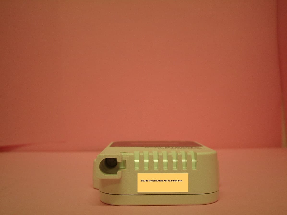
Click to zoom
Application Details
- Equipment Class
- DTS - Digital Transmission System
- Date of Grant
- Dec 02, 2020
- Application Purpose
- Original Equipment
- Date of Application
- Dec 02, 2020
- Equipment Note
- Data Logger Remote Unit
- Frequency Range
- 2402.00000000 - 2480.00000000
- Company
- TandD Corporation
- Country
- Japan
Documents & Files
Document Text
Text extracted from the exhibit documents filed with the FCC. Open a document above to read the original.
Users Manual
Thank you for purchasing our product. To ensure safe and proper operation, please read this manual thoroughly before use. Overview The RTR501B, RTR502B, RTR503B and RTR507B are wireless data loggers designed to measure and record temperature and humidity. Recorded data is then automatically collected by the Base Unit via wireless communication and downloaded for archive and analysis. As a Remote Unit, the RTR501B / 502B / 503B / 507B requires a Base Unit to carry out wireless communication. (Compatible Base Units: RTR500BC, RTR500BW, RTR-500MBS-A, RTR- 500DC, RTR-500, RTR-500NW/AW) For the operation and configuration of the Base Unit, refer to the instruction manual attached to the Base Unit or the RTR500B Series Help available on T&D Website. Wireless Thermo Recorder RTR501B / 502B / 503B / 507B is re- ferred to as the “(data) logger” or “device” in this manual. tandd.com © Copyright T&D Corporation. All rights reserved. 2020.09 16508160003 (1st Edition) Printed on recycled paper. Package Contents RTR501B Internal Temp Sensor RTR502B Temp Sensor TR-5106 (Included) RTR503B Temp-Humidity Sensor TR-3310 (Included) RTR507B High Precision Temp-Humidity Sensor SHB -3101 (Included) Common Accessories • Lithium Battery LS14250 (or Large Capacity Battery Adaptor Kit RTR-500B1 for L type model) • Strap (Not included with L type model) • Manual Set (Warranty Included) Part Names Make sure that the sensor is completely inserted until you hear a “click” sound. Sensor Jack LCD Display Antenna Optical Communication Port <Side> (L type) <Side><Front><Back> Installing the Battery Recording starts automatically by inserting the battery with the default or previous settings. Battery Cover Rubber Packing Screw Lithium Battery Default Settings Recording ModeEndless Recording Interval10 minutes Recording Start Method Immediate Start • Make sure to use the proper type and size screwdriver. (Phillips head #1 screwdriver is recommended.) • Insert the supplied battery with the tube attached. When using a CR2 lithi- um battery, the tube is not necessary. • Before closing the cover, check the rubber packing for dust or scratches, as they can reduce the water resis- tance of the rubber. • Be sure to completely close the cover. Make sure not to over tighten the screws. • Appropriate Tightening Torque: 20N·cm to 30N·cm (2Kgf·cm to 3Kgf·cm) Battery Replacement When it is time for the battery to be replaced, a battery warning mark will appear. Please change the battery as soon as possible if this mark appears. If you continue to use the logger without changing the battery, the current temperature and [bAtt] will be displayed alternately and wireless communication will stop. (Recording will continue.) Alternating Display • If the battery is further left unchanged, the display will automatically shut off and all previously recorded data will be lost. • Although the logger continues to work for a period after the battery has been removed, leaving the device without a battery until the LCD display goes blank will cause all recorded data to be lost. Remote Unit Registration Using the software of the compatible Base Unit, carry out Remote Unit Registration via optical or Bluetooth. Optical Communication Connect the Base Unit to a PC with a USB cable, and place the data logger face down to align the communication areas as shown be- low. Bluetooth ® Communication When the RTR500BW is a Base Unit, it is possible to make Base Unit and Remote Unit settings from nearby mobile devices using Blue- tooth. Wireless Thermo Recorder RTR501B / 502B / 503B / 507B User's Manual Specifications ModelRTR501B / 501BLRTR502B / 502BLRTR503B / 503BLRTR507B / 507BL Measurement Channels Temperature 1chTemperature 1chTemperature 1ch, Humidity 1chTemperature 1ch, Humidity 1ch SensorThermistor (Internal)ThermistorThermistorPolymer ResistanceThermistorPolymer Resistance Measurement Range -40 to 80°C-60 to 155°C0 to 55°C10 to 95%RH-25 to 70°C0 to 99 %RH (*1) AccuracyAvg. ±0.5°C Avg. ± 0.3°C at -20 to 80°C Avg. ±0.5°C at -40 to -20°C, 80 to 110°C Avg. ± 1.0°C at -60 to -40°C, 110 to 155°C Avg. ± 0.3°C ±5 %RH at 25°C, to 0%RH ±0.3°C at 10 to 40°C ±0.5°C Others ±2.5 %RH at 15 to 35°C, 30 to 80%RH Measurement Resolution 0.1°C0.1°C0.1°C1 %RH0.1°C0.1 %RH Responsiveness Thermal Time Constant: Approx. 15 min. Approx. 25 min. (L Type) Response Time (90%): Approx. 35 min. Approx. 47 min. (L Type) Thermal Time Constant: Approx. 30 sec. (in air) Approx. 4 sec. (in agitated water) Response Time (90%): Approx. 80 sec. (in air) Approx. 7 sec. (in agitated water) Response Time (90%): Approx. 7 min.Response Time (90%): Approx. 7 min. Logging Capacity 16,000 readings16,000 readings 8,000 data sets (One data set con- sists of readings for all channels in that type of unit.) 8,000 data sets (One data set consists of readings for all channels in that type of unit.) Recording Interval 1, 2, 5, 10, 15, 20, 30 sec. 1, 2, 5, 10, 15, 20, 30, 60 min. (Total of 15 choices) Recording Mode (*2) Endless: Overwrite the oldest data when capacity is full One Time: Stop recording when capacity is full Communica- tion Interfaces Short Range Wireless Communication Frequency Range: 902 to 928 MHz RF Power: 7 mW Transmission Range: About 150 m if direct and unobstructed. Bluetooth 4.2 (Bluetooth Low Energy) (*3) Optical Communication Power Lithium Battery LS14250 x 1 L Type: Large Capacity Battery Adaptor Kit (RTR-500B1) x 1 (*4) External Power Adaptor Kit RTR-500A2 (*5) Battery Life (*6)About 10 months L Type: About 4 years DimensionsH 62 mm x W 47mm x D 19 mm L Type: H 62 mm x W 47 mm x D 46.5 mm (excluding protrusions and sensor) WeightApprox. 50 g, L Type: Approx. 65 g Operating Environment -40 to 80°C Wireless Communication -30 to 80°C Waterproof Capacity IP67 (immersion proof)IP64 (splash proof / rated for use in daily life) (*7) Compatible Base Units RTR500BC, RTR500BW RTR-500DC, RTR-500MBS-A, RTR-500NW/AW (*8)(*9) RTR-500 (*9) *1: When continually used in environments with temperatur…
Text truncated - open the document above for the full version.
Users Manual
RTR500B Series Please Read First Terms to be Used Base UnitRTR500BC / 500BW Remote UnitRTR501B / 502B / 503B / 505B / 507B RepeaterRTR500BC (to expand the wireless communication range) Safety Precautions and Instructions The following items should be strictly obeyed for the safe usage of the product, and for protecting yourself and other people from bodily harm and/or damage to property. Before use, please carefully read and follow the safety precautions outlined below. Explanation of Symbols <Warning Symbols> DANGER These entries are actions that, if taken, may cause serious personal physical damage or death. CAUTION These entries are actions that if taken may lead to physical injury or damage to persons or things. <Picture Symbols> Denotes an import- ant warning or caution. Denotes a forbidden action. Denotes an action that should be carried out. DANGERTo Prevent Serious Accidents Do not disassemble, repair or modify the product and accessories. Do not use the product in any environment that is exposed to chemicals and harmful gases. Doing so may cause corrosion and/or other danger to the product. Also, coming in contact with hazardous substances may cause bodily harm to the user or people nearby. The RTR500B Series Base Units, temp-humidity sensors, and input modules (for RTR505B) are not water resistant. If liquid enters the product, immediately remove the power and stop using it. Do not touch the Base Unit or Repeater with wet hands. Do not connect or disconnect the power supply, cables, or sensors with wet hands. These actions may cause electric shock. Do not touch the product or AC adaptor during thunder and lightning. It may also cause electric shock. This product has been designed for private and/or industrial use only. It should not be used in situations where strict safety precautions are necessary such as with medical equipment, or in systems directly or indirectly connected with human life or well-being. Do not drop or expose the product to a strong impact. Do not modify or cut the communication cable, AC adaptor cord, or sensor. Also, do not twist, pull on or swing them. To prevent damage to the product from static electricity, remove static electricity from your body by touching metal around you (such as a door knob and window frame) before touching the unit. Please be careful not to touch the product during or after use in overly hot or cold environments. It may cause burns or frostbite. Place and store the product and accessories out of the reach of children. We are not responsible for any damage, malfunction or trouble, whether direct or indirect, caused by the use of our product. Do not use any power, battery, sensor, or cable other than those specified by T&D Corporation. Do not put anything on top of the product, AC adaptor or cable. It may cause overheating. Do not disconnect the communication cable during USB, LAN, or wireless communi- cation. Doing so may cause adverse effects to the Base Unit and/or PC. Make sure that the cable and AC adaptor are inserted fully, so as not to cause an improper connection. Also, when unplugging the cable from the unit, do not pull the cord, but hold the connector to disconnect. If the unit produces heat, emits smoke or a strange smell, or makes unusual noises, immediately remove the power supply and stop using it. If the unit is connected to the PC, disconnect it before removing the power supply. CAUTIONNotes about the Base Unit / Repeater • Do not use the product in wet areas or places exposed to water such as bathroom. • When connecting the product to your PC, make sure to follow all warnings and directions from your computer manufacturer. • We shall not guarantee the operation of the device if it has been connected to a PC using a USB hub or a USB extension cable. CAUTIONNotes about the Remote Unit • Contact with oil may cause cracks to appear in the casing of the unit. When using the unit in environments where such oils are present, please insure that it is protected from contact through use of a polyethylene bag or other means. • The following may cause water or foreign objects to enter the unit - Closing the case with dirt, dust, or hair on the rubber packing or between the unit and rubber packing - Scratches on the rubber packing - Involving a significant temperature change (especially from high to low) while the product is wet CAUTION Places not suitable for installation and storage (Base Unit / Remote Unit) • Areas exposed to direct sunlight • Areas subject to direct flames or heaters, as well as areas in which hot air accumulates and creates extremely high temperatures • Areas exposed to static electricity • Areas exposed to strong magnetic fields • Areas exposed to dampness • Areas subject to condensation or wet areas • Areas exposed to excessive vibration • Areas exposed to excessive smoke, dust or dirt. CAUTIONOther Precautions • Use the product in the specified operating environment, and do not use in any other purposes than those intended. • Condensation may occur inside the case when the product is moved from one environ- ment to another where there is a great difference in temperature. Do not use in areas susceptible to condensation. • Do not insert any foreign objects into any of the units' jacks. • If the unit gets dirty, wipe it with a clean cloth. • Make sure to remove dust and dirt from connection interfaces of the AC adaptor, cables, and sensors. • Please note that this document has been written based on the presupposition that details about contracts with an Internet provider, specific network environments and the set-up of any other necessary equipment to enable network connection has already been taken care of by the User and that connection has been confirmed as workable. T&D Corpora- tion shall not be responsible for any damages which a contractor, a user or a third party may suffer, whether direct or indirect, due to the inability to communicate or use communication devices. • Please be careful not to l…
Text truncated - open the document above for the full version.
Users Manual
Wireless Data Recorder RTR505B User’s Manual Thank you for purchasing our product. To ensure safe and proper operation, please read this manual thoroughly before use. Overview RTR505B is a data logger designed to measure and record different items depending on the input module to be con- nected: temperature (Thermocouple, Pt), analog signal (4-20mA, DC voltage), and pulse. Recorded data is then automatically collected by the Base Unit via wireless communication and downloaded for archive and analysis. As a Remote Unit, RTR505B requires a Base Unit to carry out wire- less communication. (Compatible Base Units: RTR500BC, RTR500BW, RTR-500MBS-A, RTR- 500DC, RTR-500, RTR-500NW/AW) For the operation and configuration of the Base Unit, refer to the instruction manual attached to the Base Unit or the RTR500B Series Help available on T&D Website. Wireless Data Recorder RTR505B is referred to as the “(data) logger” or “device” in this manual. tandd.com © Copyright T&D Corporation. All rights reserved. 2020.09 16508210003 (1st Edition) Printed on recycled paper. Input Modules (Sold Separately) Measurement ItemInput ModuleLCD Displayed Items Temperature (Type K, J, T, S) Thermocouple Module (TCM-3010) Measurement, Unit of Measurement, Sensor Type, Operational Status Temperature (Pt100, Pt1000) PT Module (PTM-3010) Measurement, Unit of Measurement, Sensor Type, Operational Status Voltage Voltage Module (VIM-3010) Measurement, Unit of Measurement, Operational Status 4-20mA 4-20mA Module (AIM-3010) Measurement, Unit of Measurement, Operational Status Pulse Pulse Input Cable (PIC-3150) Measurement, Unit of Measurement, Operational Status • Before using the pulse input cable, it is necessary to set the measurement item to “pulse type” in the Remote Unit Settings of the application. • In order to change the measurement item, initialize the Remote Unit without connecting the input module and then redo the Remote Unit registration and settings. Make sure that the module is completely inserted until you hear a “click” sound. Installing the Battery Recording starts automatically by inserting the battery with the default or previous settings. Battery Cover Rubber Packing Screw Lithium Battery Default Settings Recording ModeEndless Recording Interval10 minutes Recording Start Method Immediate Start • Make sure to use the proper type and size screwdriver. (Phillips head #1 screwdriver is recommended.) • Insert the supplied battery with the tube attached. When using a CR2 lithi- um battery, the tube is not necessary. • Before closing the cover, check the rubber packing for dust or scratches, as they can reduce the water resis- tance of the rubber. • Be sure to completely close the cover. Make sure not to over tighten the screws. • Appropriate Tightening Torque: 20N·cm to 30N·cm (2Kgf·cm to 3Kgf·cm) Battery Replacement When it is time for the battery to be replaced, a battery warning mark will appear. Please change the battery as soon as possible if this mark appears. If you continue to use the logger without changing the battery, the current temperature and [bAtt] will be displayed alternately and wireless communication will stop. (Recording will continue.) Alternating Display • If the battery is further left unchanged, the display will automatically shut off and all previously recorded data will be lost. • Although the logger continues to work for a period after the battery has been removed, leaving the device without a battery until the LCD display goes blank will cause all recorded data to be lost. Remote Unit Registration Using the software of the compatible Base Unit, carry out Remote Unit Registration via optical or Bluetooth. Optical Communication Connect the Base Unit to a PC with a USB cable, and place the data logger face down to align the communication areas as shown below. Bluetooth ® Communication When the RTR500BW is a Base Unit, it is possible to make Base Unit and Remote Unit settings from nearby mobile devices using Bluetooth. Package Contents • RTR505B or RTR505BL (Large Battery Type) • Lithium Battery LS14250 (or Large Capacity Battery Adaptor Kit RTR-500B1 for L type model) • Strap (Not included with L type model) • Manual Set (Warranty Included) Part Names Module Jack LCD Display Antenna Optical Communication Port <Side> (L type)<Side><Front><Back> Basic Measurement Display Display varies depending upon the input module connected. Temperature (Thermocouple / Pt100 / Pt1000) Temperature measurement (Unit: °F / °C) will be displayed. Sensor type will be displayed under the measurement; the factory default setting is Type K and Pt (Pt100). The sensor type setting can be changed in the Remote Unit Settings of the application. Voltage Voltage measurement (Unit: V / mV) will be displayed. Due to the wide measurement range, the device has been set by default to adjust the decimal point automatically to display the measurement in V. The unit of display can be changed in the Remote Unit Settings of the application. 4-20mA 4-20mA measurement (Unit: mA) will be displayed. Pulse There are two display methods for the pulse measurement. The display method can be changed in the Remote Unit Settings of the application. Pulse Rate (Max: 61439) The most recent pulse count (Unit: P) for the recording interval period will be displayed. The display will be refreshed every one-sixtieth of the recording interval (at minimum of every one second). 50,500 pulse count will be displayed as [50.50P] with “ K “ below the measurement value. The display is in units of 10 pulses. Total Pulse Count The cumulative number of pulses (Unit: P) will be displayed from 0 to 9999. The displayed count will be refreshed every one second, and upon exceeding 9999, the count will start over again from 0. How to Read the LCD Display [REC] MarkShows the recording status. ON: Recording in progress BLINKING: Waiting for programmed start OFF: Recording stopped [ONETIME] MarkShows the recording mode. ON: One Time OFF: Endless Battery Warning M…
Text truncated - open the document above for the full version.
Cover Letter(s)
L JIii& .. , ■''"' ., ,, 817-1 Shimadachi Matsumoto, Nagano 390-0852 Japan TEL +81-263-40-0131 FAX +81-263-40-3152 http://www.tandd.com/ October 1 6, 2020 Federal Communications Commission Authorization and Evaluation Division 7435 Oakland Mills Road Columbia, MD 20146 S UBJECT: Confidentiality request regarding applications for certification of FCC ID: SRD10100 and FCC ID: SRD50100 T o Whom It May Concern: Pursuant to Sec tions 0.457 and 0.459 of the Commission's Rules, we hereby request confidential treatment of information accompanying this application as outlined below. Schematics, block diagrams, circuit descriptions The above materials contain trade secrets and proprietary information not customarily released to the public. The public disclosure of these materials may be harmful t o the applicant and provide unjustified benefits to its competitors. Regards, a.o� Akemi Oana International Business Department Chief TandD Corporation T & D CORPORATION
External Photos
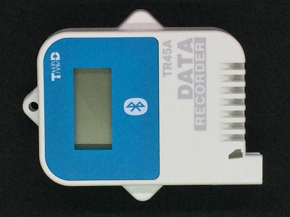
APPLICANT: TANDD CORPORATION FCC ID: SRD50100 IC: 5558A-50100 EXTERNAL PHOTOS Model: RTR501B FRONT VIEW REAR VIEW TOP VIEW BOTTOM VIEW LEFT SIDE VIEW RIGHT SIDE VIEW MODEL: RTR502B Front view REAR VIEW Model: RTR503B FRONT VIEW REAR VIEW Model: RTR505B FRONT VIEW REAR VIEW MODEL: RTR507B FRONT VIEW REAR VIEW MODELS RTR502B, RTR503B, RTR505B, RTR507B TOP VIEW BOTTOM VIEW RIGHT SIDE VIEW LEFT SIDE VIEW
ID Label/Location Info
47 62 23.4 85.4 58 19 Serial No. Serial No. 岡崎 RTR501B(US) 外観図 20.09.18 設計 製図 検図 承認 内 容 年 月 日担当 株式会社 ティアンドデイ 材料 処理 品名 製品コード 0 0.5 0.5 6 6 30 30 120 120 350 350 1000 ±0.05 ±0.1 ±0.5±0.8 1 2 3 ±0.2±0.3 差 公 度 尺 位 単 1:1 mm
ID Label/Location Info
47 62 23.4 89.4 58 19 Serial No. Serial No. RTR502B(US) 外観図 岡崎 20.09.18 設計 製図 検図 承認 内 容 年 月 日担当 株式会社 ティアンドデイ 材料 処理 品名 製品コード 0 0.5 0.5 6 6 30 30 120 120 350 350 1000 ±0.05 ±0.1 ±0.5±0.8 1 2 3 ±0.2±0.3 差 公 度 尺 位 単 1:1 mm
ID Label/Location Info
47 62 23.4 89.4 58 19 Serial No. Serial No. RTR503B(US) 外観図 岡崎 20.09.18 設計 製図 検図 承認 内 容 年 月 日担当 株式会社 ティアンドデイ 材料 処理 品名 製品コード 0 0.5 0.5 6 6 30 30 120 120 350 350 1000 ±0.05 ±0.1 ±0.5±0.8 1 2 3 ±0.2±0.3 差 公 度 尺 位 単 1:1 mm
ID Label/Location Info
47 62 23.4 89.4 58 19 Serial No. Serial No. RTR507B(US) 外観図 岡崎 20.09.18 設計 製図 検図 承認 内 容 年 月 日担当 株式会社 ティアンドデイ 材料 処理 品名 製品コード 0 0.5 0.5 6 6 30 30 120 120 350 350 1000 ±0.05 ±0.1 ±0.5±0.8 1 2 3 ±0.2±0.3 差 公 度 尺 位 単 1:1 mm
RF Exposure Info
Timco Test Report # TR_3827-20_RF Exp SAR Exclusion Rpt_3 Revision: 3 Issue Date: December 16, 2020 Final Test Date: December 16, 2020 An IIA Company Test Report - RF Exposure Evaluation / SAR Exclusion Prepared For: TANDD CORPORATION Approved for Release By: Signature: Name & Title: Bruno Clavier, General Manager Date of Signature 12/16/2020 This test report shall not be reproduced except in full without the written and signed permission of Timco Engineering Inc. (IIA). This test report relates only to the items tested as identified and is not valid for any subsequent changes or modifications made to the equipment under test. Timco Engineering, Inc., an IIA Company 849 NW State Road 45, Newberry, Florida 32669 (352) 472-5500 / [email protected] Page 2 of 8 This test report shall not be reproduced except in full without the written and signed permission of Timco Engineering Inc. (IIA). Table of Contents 1. CUSTOMER INFORMATION ........................................................................................................................................................................... 3 2. LOCATION OF TESTING ................................................................................................................................................................................. 3 2.1 TEST LABORATORY .................................................................................................................................................................................................... 3 2.2 TESTING WAS PERFORMED, REVIEWED BY ................................................................................................................................................................4 3. TEST SAMPLE(S) (EUT/DUT) ........................................................................................................................................................................... 4 3.1 DESCRIPTION OF THE EUT ........................................................................................................................................................................................ 5 4. SAR EXCLUSION CALCULATION: ................................................................................................................................................................. 6 5. HISTORY OF TEST REPORT CHANGES ........................................................................................................................................................ 7 Timco Engineering, Inc., an IIA Company 849 NW State Road 45, Newberry, Florida 32669 (352) 472-5500 / [email protected] Page 3 of 8 This test report shall not be reproduced except in full without the written and signed permission of Timco Engineering Inc. (IIA). 1. Customer Information Applicant: TANDD Corporation USA Address: 817-1-Shimadachi, Matsumoto, Nagano, Japan 390-0852 Contact: Akemi Oana Telephone: 81-263-40-0131 Email address: [email protected] 2. Location of Testing 2.1 Test Laboratory Timco Engineering Inc. is a subsidiary of Industrial Inspection & Analysis, Inc. (“IIA”). Testing was performed at Timco’s permanent laboratory located at 849 NW State Road 45, Newberry, Florida 32669 FCC test firm # 578780 FCC Designation # US1070 FCC site registration is under A2LA certificate # 0955.01 ISED Canada test site registration # 2056A EU Notified Body # 1177 For all designations see A2LA scope # 0955.01 Timco Engineering, Inc., an IIA Company 849 NW State Road 45, Newberry, Florida 32669 (352) 472-5500 / [email protected] Page 4 of 8 This test report shall not be reproduced except in full without the written and signed permission of Timco Engineering Inc. (IIA). 2.2 Testing was performed, reviewed by Dates of Testing: October 14 – December 16, 2020 Signature: Name & Title: Franklin Rose, EMC Specialist Date of Signature (YYYY-MM-DD): 2020-12 -16 Signature: Name & Title: Tim Royer, EMC Engineer Date of Signature (YYYY-MM-DD): 2020-12 -16 Timco Engineering, Inc., an IIA Company 849 NW State Road 45, Newberry, Florida 32669 (352) 472-5500 / [email protected] Page 5 of 8 This test report shall not be reproduced except in full without the written and signed permission of Timco Engineering Inc. (IIA). 3. Test Sample(s) (EUT/DUT) The test sample was received: October 14, 2020 3.1 Description of the EUT A description as well as unambiguous identification of the EUT(s) tested. Where more than one sample is required for technical reasons (such as the use of connected units for the purpose of conducted output power testing where the product units will have integral antennas), each specific test shall identify which unit was tested. Identification FCC ID: SRD50100 Brief Description Data Logger Remote Unit Type of Modular n/a Model(s) # RTR501B, RTR502B, RTR503B, RTR505B, RTR507B Firmware version n/a Software version n/a Serial Number n/a Technical Characteristics Technology 900 MHz FSK (The host also contains 2.4 GHz BLE) Frequency Range 902-928 MHz; 2400-2483.5 MHz RF O/P Power (Max.) 7.2 dBm (5.25 milliwatts) Modulation FSK Bandwidth & Emission Class 552.55 kHz Number of Channels 21 Duty Cycle 10% Antenna Gain (for each ant.) 2.15 dBi Antenna Connector SMA Voltage Rating (AC or Batt.) Battery Antenna Characteristics Antenna Frequency Range Mode / BW Antenna Gain 1 902-928 MHz n/a 2.15 dBi 2 2.4 – 2.4835 GHz n/a 0 dBi Timco Engineering, Inc., an IIA Company 849 NW State Road 45, Newberry, Florida 32669 (352) 472-5500 / [email protected] Page 6 of 8 This test report shall not be reproduced except in full without the written and signed permission of Timco Engineering Inc. (IIA). 4. SAR EXCLUSION CALCULATION: 900 MHz Radio Frequency Band Separation Distance (mm) Max Power + Tolerance (dBm) Max Power + Tolerance (mW) SAR Exclusion Value 902-928 MHz57.205.251.01 2.4 GHz Radio Frequency Band Separation Distance (mm) Max Power + Tolerance (dBm) Max Power + Tolerance (mW) SAR Exclusion Value 2…
Text truncated - open the document above for the full version.
Test Report
Timco Test Report # TR_3827-20_FCC_15.247_900MHz_4 Revision: 4 Issue Date: October 14, 2020 Final Test Date: October 29, 2020 An IIA Company Test Report - FCC PART 15.247 (DTS) Prepared For: TANDD Corporation Approved for Release By: Signature: Name & Title: Bruno Clavier, General Manager Date of Signature 10/14/2020 This test report shall not be reproduced except in full without the written and signed permission of Timco Engineering Inc. (IIA). This test report relates only to the items tested as identified and is not valid for any subsequent changes or modifications made to the equipment under test. Timco Engineering, Inc., an IIA Company 849 NW State Road 45, Newberry, Florida 32669 (352) 472-5500 / [email protected] Page 2 of 41 This test report shall not be reproduced except in full without the written and signed permission of Timco Engineering Inc. (IIA). Table of Contents 1. CUSTOMER INFORMATION ........................................................................................................................................................................... 4 1.1 TEST RESULT SUMMARY ............................................................................................................................................................................................4 2. LOCATION OF TESTING ................................................................................................................................................................................. 6 2.1 TEST LABORATORY .................................................................................................................................................................................................... 6 2.2 TESTING WAS PERFORMED, REVIEWED BY ................................................................................................................................................................ 6 3. TEST SAMPLE(S) (EUT/DUT) ........................................................................................................................................................................... 7 3.1 DESCRIPTION OF THE EUT ........................................................................................................................................................................................ 7 3.2 CONFIGURATION OF EUT ......................................................................................................................................................................................... 8 3.3 TEST SETUP OF EUT .................................................................................................................................................................................................. 8 4. TEST METHODS & APPLICABLE REGULATORY LIMITS ............................................................................................................................ 9 4.1 TEST METHODS/STANDARDS/GUIDANCE: ............................................................................................................................................................... 9 4.2 APPLIED LIMITS AND REGULATORY LIMITS: .............................................................................................................................................................. 9 5. MEASUREMENT UNCERTAINTY .................................................................................................................................................................... 9 6. ENVIRONMENTAL CONDITIONS ................................................................................................................................................................. 9 6.1 TEMPERATURE …
Text truncated - open the document above for the full version.
Contact Information
Applicant
Akemi Oana(Sales Department)
Test Firm
Timco Engineering, Inc.Bruno Clavier
Technical Specifications
| # | Rule Parts | Frequency Range | Power Output |
|---|---|---|---|
| 2 | 15C | 2.40 GHz - 2.48 GHz | 1.12 mW |
Other Applications from TandD Corporation
SRD50150
Sep 26, 2024Data Logger
Equipment Class
DTS - Digital Transmission System
SRD50140
Apr 08, 2023Data Logger
Equipment Class
DTS - Digital Transmission System
SRD50110
Jul 11, 2021Data Logger
Equipment Class
DTS - Digital Transmission System
SRD10100
Dec 02, 2020Data Logger Base Unit
Equipment Class
DTS - Digital Transmission System
SRD10090
Feb 12, 2015900 MHz BAND TRANSMITTER WITH GSM MODULE
Equipment Class
DSS - Part 15 Spread Spectrum Transmitter