SRD50150Data Logger
TandD Corporation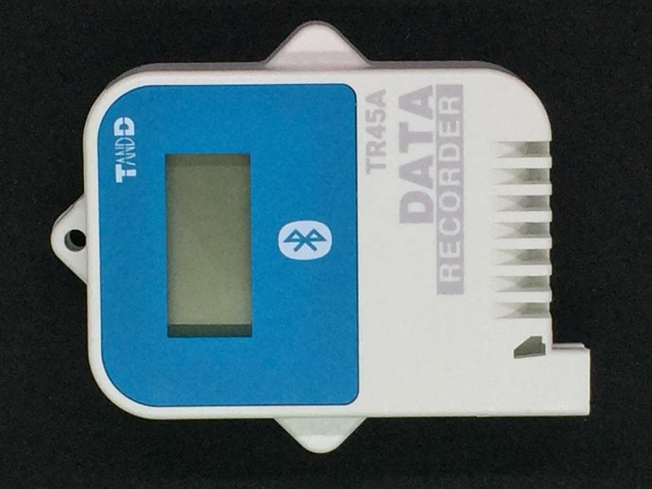
Click to zoom
Application Details
- Equipment Class
- DTS - Digital Transmission System
- Date of Grant
- Sep 26, 2024
- Application Purpose
- Original Equipment
- Date of Application
- Sep 26, 2024
- Equipment Note
- Data Logger
- Frequency Range
- 2402.00000000 - 2480.00000000
- Company
- TandD Corporation
- Country
- Japan
Documents & Files
Document Text
Text extracted from the exhibit documents filed with the FCC. Open a document above to read the original.
Users Manual
The LCD Display Recording StatusON: Recording in progress OFF: Recording stopped BLINKING: Waiting for programmed start Recording ModeON (One Time): Upon reaching logging capacity, recording automatically stops. OFF (Endless): Upon reaching the logging capacity, the oldest data is overwritten and recording continues. Battery Warning Mark When this appears, replace the battery as soon as pos- sible. A low battery may cause communication errors. * If the battery is left unchanged until the LCD display goes blank, all recorded data in the logger will be lost. Communication Status Blinks while communicating with the application. Display Examples Display varies depending upon the input module connected. Temperature (Thermocouple, Pt100 / Pt1000) Sensor type will be displayed below the measurement. (Unit: °F / °C) : Thermocouple Type, : Pt100, : Pt1000 Default setting is Type K and Pt. * The sensor type setting can be changed in the application. Voltage The measurement range, recording method, and preheat settings can be made in the application. Measurement Range: V Range 0 to 22V, mV Range 0 to 999.9mV Default setting is V Range. * Due to the wide measurement range, the device has been set by default to adjust the decimal point automatically to display the measurement in V. 4-20mA The recording method ("Average Value" or "Instantaneous Value") can be selected in the application. (Unit: mA) Pulse There are two display methods as follows. The display method can be changed in the application. (Unit: P) Pulse Rate (Max: 61439) The most recent pulse count for the recording interval period will be displayed. The display will be refreshed every one-sixtieth of the recording interval (at mini- mum of every one second). * 45,000 pulse count will be displayed as [45.00P] with K (x1000) below the measurement value (in units of 10 pulses). Total Pulse Count (0 to 9999) Indicates the cumulative number of pulses since recording start. The display will be refreshed every one second. * Upon exceeding 9999, the count will start over again from 0. Messages Low Battery This appears if, after the battery warning mark is displayed, no action is taken and the battery level becomes lower. (The measure- ment and the [bAtt] sign will alternately appear in the LCD.) * Bluetooth communication is now stopped. * If the battery is left unchanged until the LCD display goes blank, all recorded data in the logger will be lost. Input Module Unrecognized or Unconnected If the display does not change after reconnecting the input mod- ule, it may be damaged. Sensor Error Indicates that the sensor is not connected or the wire is broken. * If nothing appears on display after reconnecting the sensor to the device, there is a possibility that the sensor or the device has been damaged. Measurement Range Exceeded This will appear if a measurement exceeds the measurement range. Display Range Exceeded When measuring voltage in mV range, the measurement in the LCD display will flash if it exceeds the display range of the device. Logging Capacity FULL Indicates that the logging capacity has been reached and record- ing has been stopped. (When recording mode is One Time) Estimated Time until Logging Capacity (16,000 readings) is Reached Rec Interval1 sec.30 sec.1 min.10 min.60 min. Time Period About 4 hours About 5 days About 11 days About 111 days About 1 year and 10 months Refer to the HELP for operational details. https://manual.tandd.com/tr4a/ Package Contents Before use, please confirm that all of the contents are included. Data LoggerLithium Battery (LS14250) Registration Code Label StrapManual Set (Warranty In- cluded) Introduction The TR4A series enables data collection and management using dedicated mobile device applications. By using our free cloud service, you can access collected data using a web browser and analyze with the T&D Graph Windows application. The following applications are supported: T&D Thermo Mobile app for device configuration, data collection and graphing, data upload to the cloud, and report creation. * Refer to the HELP for operational details. https://manual.tandd.com/thermo/ TR4 Report TR4 Report is a mobile application that collects recorded data and generates a report for a specified period. * Refer to the HELP for operational details. https://manual.tandd.com/tr4report/ Device Preparation TR45A is a data logger designed to measure and record different items depend- ing on the input module (Sold Separately) to be connected: temperature (Ther- mocouple, Pt), analog signal (4-20mA, DC voltage), and pulse. Battery Installation & Input Module Connection The logger starts recording automatically upon battery installation and input module recogni- tion. Default Settings Recording Interval: 10 minutes Recording Mode: Endless Measurement ItemInput Module (Type) Temperature (Type K, J, T, S, R) Thermocouple Module (TCM- 3010) Temperature (Pt100, Pt1000) PT Module (PTM-3010) Voltage Voltage Module (VIM-3010) 4-20mA4-20mA (AIM-3010) PulsePulse Input Cable (PIC-3150) * Before using the pulse input cable, it is necessary to set the mea- surement item to “pulse type" in the application. * Sensor not provided / Pt sensor available as option © Copyright T&D Corporation. All rights reserved. 2024.04 16508310018 (3rd Edition) User's Manual Bluetooth® Data Recorder TR45A BluetoothCellular WiFi Internet T&D Thermo (Basic Operations) Download the App 1.1 “T&D Thermo” is available for free download from the App Store or Google Play Store. Set up a T&D WebStorage Service Account 2.1 If you don't use the WebStorage: Go to Step 3.1 In order to send data to the WebStorage, it is necessary to add an account to the App. 2.2 If you don’t have a WebStorage account: Tap ① [Menu Button] on the upper left corner of the app home screen → ② [Account Management] → ③ [Selected Account] → ④ [Get a User ID] to create a new account. Go back to the home screen and tap ① [Menu Button] → ② [Account Management] → ③ [Selected Account] → ⑤ [Apply] a…
Text truncated - open the document above for the full version.
Users Manual
© Copyright T&D Corporation. All rights reserved. 2024. 06 16508310016 (5th Edition) Bluetooth® Thermo Recorder Model No. TR41A, TR42A, TR43A, TR45A TR4A series Safety Instructions and Specifications Thank you for purchasing our product. Please read carefully the following safety instructions and specifications to prevent damage to personnel and property, and to ensure safe and proper use of this product. Explanation of Symbols ! DANGER These entries are actions that, if taken, may cause serious personal physical damage or death. ! CAUTION These entries are actions that if taken may lead to physical injury or damage to persons or things. Denotes an im- portant warning or caution. Denotes a forbid- den action. Denotes an action that should be carried out. ! DANGER To Prevent Serious Accidents Do not disassemble, repair or modify the unit. Do not use the unit in any environment that is exposed to chemicals and harmful gases. Doing so may cause corrosion and/or other danger to the product. Also, coming in contact with hazardous substances may cause bodily harm to the user or people nearby. The TR45A and temperature-humidity sensors (for TR43A) are not water resistant. Only use in an environment where there is no condensation or possibility of becoming wet. If liquid enters the product, immediately remove the battery and stop using it. If the unit is subjected to significant temperature change while wet, it may cause condensation inside the case. Especially be careful with temperature changes from high to low; if the unit has condensation on the inside, it may cause malfunction, damage, and/or unexpected accidents. Do not insert or replace batteries or sensors with wet hands. Do not touch the product, sensor cable or AC adaptor during thunder and lightning. Doing so may cause electric shock. Please be careful not to touch the product or sensor during or after use in overly hot or cold environ- ments. It may cause burns or frostbite. This product has been designed for private and/or industrial use only. It should not be used in situations where strict safety precautions are necessary such as with medical equipment, or in systems directly or indirectly connected with human life or well-being. Do not drop or expose the unit to a strong impact. Do not cut or process the sensor cables. Also, do not twist, pull on or swing them. To prevent damage to the unit from static electricity, remove static electricity from your body by touching metal around you (such as a door knob and window frame) before touching the unit. Store the unit and battery out of the reach of children. Do not use any sensors other than those specified by T&D Corporation. Make sure the sensor is inserted fully, so as not to cause an improper connection. Also, when unplugging the sensor from the unit, do not pull the cord, but hold the connector to disconnect. If the unit produces heat, emits smoke or a strange smell, or makes unusual noise, immediately remove the battery and stop using it. Check the rubber packing inside the case for deterioration, damage, dust and dirt, and periodically replace with the silica gel. Contact with oil may cause cracks to appear in the casing of the unit. When using this unit in environ- ments where such oils are present, please ensure that it is protected from contact through use of a polyethylene bag or other means. ! DANGER Places NOT Suitable for Installation and Storage • Areas exposed to excessive vibration • Areas exposed to excessive smoke, dust or dirt. • Areas exposed to direct sunlight • Areas subject to direct flames or heaters, as well as areas in which hot air accumulates and creates extremely high temperatures • Areas exposed to static electricity • Areas exposed to strong magnetic fields ! CAUTION About the Sensors Temperature Sensor TR-5106 (Provided with TR42A) • Do not bend or press the last 5cm to the tip of the sensor, as this may damage it. • Insert the sensor tip to at least 5cm or more to obtain an accurate temperature measurement. • Use the sensor within its resistance range (-70 to 180°C). Temperature-Humidity Sensor THB3001 (Provided with TR43A) • This sensor is not water resistant. Do not expose to condensation, dampness, corrosive gases or organic solvents. If the sensor gets wet, immediately remove the sensor from the unit and wipe it with a clean cloth as soon as possible. Then allow the sensor to dry in normal room temperature before using it again. • Do not expose the sensor to a strong impact. This may adversely affect measurement accuracy and cause damage or malfunction. • Continued use may cause a decrease in the sensor’s accuracy and sensitivity even under normal operational conditions. Periodic calibration may be required. • When the sensor is not to be used for a long period of time, please store it at normal temperature and humidity. ! CAUTION Others • Use the unit and the sensor in the specified operating environment, and do not use in any other purposes than those intended. • Do not allow dust or foreign objects to get into the sensor jack. • If the product gets dirty, wipe it with a clean cloth. • Battery terminals may provide insufficient contact due to age or vibration. This may lead to data loss. • Please be careful not to let a third party know of your registration code. The registration code cannot be reis- sued or changed. ! CAUTION About the Lithium Battery • Do not install the battery in the wrong direction. Doing so may result in product malfunction, battery leakage, overheating or explosion. • Do not short the battery with metal objects. Doing so could cause leakage, overheating, fire or explosion. When carrying or storing batteries, avoid direct contact with metal objects by putting them in a separate container. • If battery fluid gets on your eyes, skin or clothes, wash thoroughly with clean water. See a doctor immediately if it gets in your eyes. • This battery is non-rechargeable and should not be recharged • Do not use any other batteries tha…
Text truncated - open the document above for the full version.
External Photos
TR45A product photo front left side right side top Bottom Back side
ID Label/Location Info
5 66 47 58 5 PMN 19 Serial Label Caution Label φ5.5 Registration Code Tamper-proof Pan Head LR Machine Screw(x2) Certification Label Certification Label HVIN The FCC/ISED certification label is attached inside the battery box. After purchasing the data logger, the user will see this label when inserting the batteries. Certification Label Scale(2:1) will be replaced by the official certification number after the product is certified. ・Material: PET thickness:0.05mm ・Base: White Text color: Black ・Surface: Laminated The label cannot be peeled off easily within the product lifetime because: ・It is laminated. ・It is attached inside the battery box. It makes difficult to contact with any materials or environmental effects. Display Panel:Polycarbonate TEIJIN KASEI 「Panlite L-1225-Z-100」 Min.thickness:1.5mm Material Upper Case, Lower Case:Polycarbonate SABIC 「LEXAN EXL9330-WH9A302」 Min.thickness:1mm FCC/ISED 4pt 5 設計 製図 検図 承認 内 容 年 月 日 担当 株式会社 ティアンドデイ 材料 処理 品名 製品コード 0 0.5 0.5 6 6 30 30 120 120 350 350 1000 ±0.05 ±0.1 ±0.5 ±0.8 1 2 3 ±0.2 ±0.3 公 差 尺 度 数 量 Doc.No.851-0803-1090 1:1 福田 24.09.05 TR45A(海外) 外観図
Internal Photos
PCB(Front) PCB(Front) Under LCD Inside Inside PCB(Back) RF antenna section Certification Label
RF Exposure Info
UL Japan, Inc. Ise EMC Lab. 4383-326 Asama-cho, Ise-shi, Mie-ken 516-0021 Japan / +81-596-24-8999 RF Exposure / MPE Calculation No. 15317913H Customer TandD Corporation Description of EUT Data Logger Model Number of EUT TR45A FCC ID SRD50150 TandD Corporation declares that Model: TR45A complies with FCC radiation exposure requirement specified in the FCC Rule 2.1091 (for mobile). RF Exposure Calculations: The following information provides the minimum separation distance for the highest gain antenna provided with the “TR45A“ as calculated from (B) Limits for General Population / Uncontrolled Exposure of TABLE 1- LIMITS FOR MAXIMUM PERMISSIBLE EXPOSURE (MPE) of §1.1310 Radiofrequency radiation exposure limits. This calculation is based on the highest EIRP possible from the system, considering maximum power and antenna gain, and considering a 1mW/cm^2 uncontrolled exposure limit. The Friis formula used was: Where P = 2.00 mW (Maximum average output power) Time average was used for the above value in consideration of 6-minutes time-averaging Burst power average was used for the above value in consideration of worst condition. G = 1.253 Numerical Antenna gain; equal to 0.98dBi r = 20 cm (Separation distance) 0.00050 mW/cm 2 Power Density Result S = 2 4r GP S
Test Report
Page. 1 ANTENNA TEST REPORT Test Place Company Name UL Japan, Inc. Ise EMC Lab. Address 4383-326 Asama-cho, Ise-shi, Mie-ken 516-0021 Japan Telephone Number +81-596-24-8999 Equipment Under Test (EUT) Description Data Logger Manufacturer TandD Corporation Model Number TR45A Frequency of Operation 2402 MHz to 2480 MHz Antenna Type Inverted F For the shape of the antenna is refer to Internal Photo. Test Procedure Test configuration EUT was placed on a platform of nominal size, 0.5 m by 0.5 m, raised 1.5 m above the conducting ground plane. The measurements were performed for both vertical and horizontal antenna polarization with the Spectrum Analyzer. The setup are shown in Figure 1. Test procedure Step 1 The tests have been measured in semi anechoic chamber at the distance of 3 m between the Substitution Antenna and the measuring Antenna, both Antennas were placed for the height 1.5 m. The Substitution Antenna has been connected to the Signal Generator. Step 2 The output power of the Signal Generator was setting value calculated by compensating the finite difference in the Antenna gain of Substitution Antenna. Step 3 The electric field strength at the distance of 3 m is received via the measurement antenna, and the reference value at that time is measured with a spectrum analyzer. Step 4 The measurements were performed for both vertical and horizontal antenna polarization. Step 5 Exchanged the Substitution Antenna to the EUT, the output power of the Signal Generator was setting value calculated by 0 dBm at the input of EUT. Step 6 The EUT was rotated a full revolution and recorded the electric field strength for each degree. Step 7 Calculate and record the difference from the value recorded in Step 6 to the value recorded in Step 3. Step 8 The measurement in steps 5 to 7 repeated with both vertical and horizontal antenna polarization, each position of XY, YZ and ZX-plane of EUT. Page. 2 Figure 1: Test Setup Setup for step 1 to 4 Setup after step 5 SG:Signal Generator SA:Spectrum Analyzer AMP:Pre Amplifier AMPSA SG Tu r n Tab le Semi Anechoic Chamber 3.0 m 1.5 m 1.5 m Horn Antenna Horn Antenna AMPSA Tu r n Tab le Semi Anechoic Chamber 3.0 m 1.5 m 1.5 m EU T SG urethane platform Horn Antenna Page. 3 Test Data Antenna Pattern and Gain Test place Ise EMC Lab. Semi Anechoic Chamber No.4 Date August 27, 2024 Temperature / Humidity 23 deg. C / 68 % RH Enginee r Yuichiro Yamazaki Mode Tx Antenna pattern (Top view) 2402 MHz-0.66 dBi Peak-0.68 dBi Peak0.98 dBi Peak 2440 MHz-0.93 dBi Peak-1.09 dBi Peak0.10 dBi Peak 2480 MHz-0.80 dBi Peak-0.53 dBi Peak-0.16 dBi Peak Antenna gain [UNIT: dBi] PeakAverage 240224402480240224402480 0.980.10-0.16Hori .-4.42- 4.57- 5.04 V e rt.- 16.19-16.36- 15.78 Avg (H/V)-7.15-7.30-7.70 Hori .-4.27-5.31-6.63 Ve rt.-5.02-4.81-4.27 Avg (H/V)-4.63-5.05-5.29 Hori .- 11.61-11.32- 11.19 Ve rt.-2.43-2.91-3.30 Hori.: HorizontalAvg (H/V)-4.94-5.33-5.66 Vert.: Vertical-5.44-5.79-6.09 Average: Result of averaging the true value of the value of each degree of angle. Frequency [MHz] Peak gain Frequency [MHz] Total XY-plane YZ-plane ZX-plane -55 -45 -35 -25 -15 -5 5 XY-plane Gain [dBi] XY-plane, Hori. XY-plane, Vert. 0 deg. 180 deg. 90 deg. 270 deg. -55 -45 -35 -25 -15 -5 5 YZ-plane Gain [dBi] YZ-plane, Hori. YZ-plane, Vert. 0 deg. 180 deg. 90 deg. 270 deg. -55 -45 -35 -25 -15 -5 5 ZX-plane Gain [dBi] ZX-pla ne, Hori. ZX-pla ne, Vert. 0 deg. 180 deg. 90 deg. 270 deg. -55 -45 -35 -25 -15 -5 5 XY-plane Gain [dBi] XY-plane, Hori. XY-plane, Vert. 0 deg. 180 deg. 90 deg. 270 deg. -55 -45 -35 -25 -15 -5 5 YZ-plane Gain [dBi] YZ-plane, Hori. YZ-plane, Vert. 0 deg. 180 deg. 90 deg. 270 deg. -55 -45 -35 -25 -15 -5 5 ZX-plane Gain [dBi] ZX-pla ne, Hori. ZX-pla ne, Vert. 0 deg. 180 deg. 90 deg. 270 deg. -55 -45 -35 -25 -15 -5 5 XY-plane Gain [dBi] XY-plane, Hori. XY-plane, Vert. 0 deg. 180 deg. 90 deg. 270 deg. -55 -45 -35 -25 -15 -5 5 YZ-plane Gain [dBi] YZ-plane, Hori. YZ-plane, Vert. 0 deg. 180 deg. 90 deg. 270 deg. -55 -45 -35 -25 -15 -5 5 ZX-plane Gain [dBi] ZX-pla ne, Hori. ZX-pla ne, Vert. 0 deg. 180 deg. 90 deg. 270 deg. Yellow highlighted area: Maximum Antenna Gain [dBi] Page. 4 Test Instruments Test Equipment Test Item LIMS ID Description Manufacturer Model Serial Last Calibration Date Cal Int APG 142011 AC4_Semi Anechoic Chamber(NSA) TDK Semi Anechoic Chamber 3m DA-10005 2023/12/13 24 APG 244710 Thermo-Hygrometer HIOKI E.E. CORPORATION LR5001 231202104 2024/01/25 12 APG 141545 DIGITAL HiTESTER HIOKI E.E. CORPORATION 3805 51201148 2024/02/01 12 APG 142230 Measure, Tape, Steel KOMELON KMC-36 - - - APG 142017 AC4_Semi Anechoic Chamber(SVSWR) TDK Semi Anechoic Chamber 3m DA-10005 2023/04/14 24 APG 141899 Spectrum Analyzer Keysight Technologies Inc E4448A MY46180655 2024/05/09 12 APG 141508 Horn Antenna 1-18GHz Schwarzbeck Mess- Elektronik OHG BBHA9120D 557 2024/05/17 12 APG 141581 MicroWave System Amplifier Keysight Technologies Inc 83017A 00650 2023/10/05 12 APG 141393 Microwave Cable Junkosha MWX221 1604S254(1 m) / 1608S088(5 m) 2024/07/06 12 APG 158264 Signal Generator Keysight Technologies Inc N5182A MY50142539 2023/09/13 12 APG 197219 Microwave cable Huber+Suhner SF126E/11PC35/11P C35/2000MM 536999/126E 2024/03/19 12 APG 141514 Horn Antenna 1-18GHz Schwarzbeck Mess- Elektronik OHG BBHA9120D 01611 2024/06/25 12 *Hyphens for Last Calibration Date and Cal Int (month) are instruments that Calibration is not required (e.g. software), or instruments checked in advance before use. The expiration date of the calibration is the end of the expired month. As for some calibrations performed after the tested dates, those test equipment have been controlled by means of an unbroken chains of calibrations. All equipment is calibrated with valid calibrations. Each measurement data is traceable to the national or international standards. Test item: APG: Antenna Pattern and Gain Page. 5 Photographs of Test Setup Test setup (Overall view) Photo 1 Photo 2 Page. 6 Test setup (Top view) Test setup (Top view)…
Text truncated - open the document above for the full version.
Test Report
Test Report No. 15317913H-C-R1 Page 1 of 32 UL Japan, Inc. Ise EMC Lab. 4383-326 Asama-cho, Ise-shi, Mie-ken 516-0021 Japan / +81-596-24-8999 RADIO TEST REPORT Test Report No. 15317913H-C-R1 Customer TandD Corporation Description of EUT Data Logger Model Number of EUT TR45A FCC ID SRD50150 Test Regulation FCC Part 15 Subpart C Test Result Complied Issue Date September 12, 2024 Remarks - Representative Test Engineer Approved By Takeshi Hiyaji Engineer Takumi Shimada Engineer CERTIFICATE 5107.02 The testing in which "Non-accreditation" is displayed is outside the accreditation scopes in UL Japan, Inc. There is no testing item of "Non-accreditation". Report Cover Page - Form-ULID-003532 (DCS:13-EM-F0429) Issue# 23.0 Test Report No. 15317913H-C-R1 Page 2 of 32 UL Japan, Inc. Ise EMC Lab. 4383-326 Asama-cho, Ise-shi, Mie-ken 516-0021 Japan / +81-596-24-8999 ANNOUNCEMENT REVISION HISTORY Original Test Report No.: 15317913H-C This report is a revised version of 15317913H-C. 15317913H-C is replaced with this report. Revision Test Report No. Date Page Revised Contents - (Original) 15317913H-C June 28, 2024 - 1 15317913H-C-R1 September 12, 2024 2.2 Product Description Corrected Rating of General Specification: DC 3.0 V to 3.6 V → DC 3.6 V 4.1 Operating Mode(s) Deleted "Conducted Spurious Emission" which was under Radiated Spurious Emission (Above 1 GHz) from the table for the Details of Operatin g Mode(s). This test report shall not be reproduced in full or partial, without the written approval of UL Japan, Inc. The results in this report appl y only to the sample tested. (Laboratory was not involved in sampling.) This sample tested is in compliance with the limits of the above re gulation. The test results in this test report are traceable to the national or international standards. This test report must not be used by the customer to claim product certification, approval, or endorsement b y the A2LA accreditation body. This test report covers Radio technical requirements. It does not cover administrative issues such as Manual or non-Radio test related Requirements. (if applicable) The all test items in this test report are conducted b y UL Japan, Inc. Ise EMC Lab. The opinions and the interpretations to the result of the description in this report are outside scopes where UL Japan, Inc. has been accredited. The information provided b y the customer for this report is identified in SECTION 1. The laboratory is not responsible for information provided by the customer which can impact the validit y of the results. For test report (s) referred in this report, the latest version (including any revisions) is always referred. Test Report No. 15317913H-C-R1 Page 3 of 32 UL Japan, Inc. Ise EMC Lab. 4383-326 Asama-cho, Ise-shi, Mie-ken 516-0021 Japan / +81-596-24-8999 Reference: Abbreviations (Including words undescribed in this report) A2LA The American Association for Laboratory Accreditation ICES Interference-Causing Equipment Standard AC Alternating Current IEC International Electrotechnical Commission AFH Adaptive Frequency Hopping IEEE Institute of Electrical and Electronics Engineers AM Amplitude Modulation IF Intermediate Frequency Amp, AMP Amplifier ILAC International Laboratory Accreditation Conference ANSI American National Standards Institute ISED Innovation, Science and Economic Develo pment Canada Ant, ANT Antenna ISO International Organization for Standardization AP Access Point JAB Japan Accreditation Board ASK Amplitude Shift Keying LAN Local Area Network Atten., ATT Attenuator LIMS Laboratory Information Management System AV Average MCS Modulation and Coding Scheme BPSK Binary Phase-Shift Keying MRA Mutual Recognition Arrangement BR Bluetooth Basic Rate N/A Not Applicable BT Bluetooth NIST National Institute of Standards and Technology BT LE Bluetooth Low Energy NS No signal detect. BW BandWidth NSA Normalized Site Attenuation Cal Int Calibration Interval NVLAP National Voluntary Laboratory Accreditation Pro gram CCK Complementary Code Keying OBW Occupied Band Width Ch., CH Channel OFDM Orthogonal Frequency Division Multiplexing CISPR Comite International Special des Perturbations Radioelectri ques P/M Power meter CW Continuous Wave PCB Printed Circuit Board DBPSK Differential BPSK PER Packet Error Rate DC Direct Current PHY Physical Layer D-factor Distance factor PK Peak DFS Dynamic Frequency Selection PN Pseudo random Noise DQPSK Differential QPSK PRBS Pseudo-Random Bit Sequence DSSS Direct Sequence Spread Spectrum PSD Power Spectral Density EDR Enhanced Data Rate QAM Quadrature Amplitude Modulation EIRP, e.i.r.p. Equivalent Isotropically Radiated Power QP Quasi-Peak EMC ElectroMagnetic Compatibility QPSK Quadri-Phase Shift Keying EMI ElectroMagnetic Interference RBW Resolution Band Width EN European Norm RDS Radio Data System ERP, e.r.p. Effective Radiated Power RE Radio Equipment EU European Union RF Radio Frequency EUT Equipment Under Test RMS Root Mean Square Fac. Factor RSS Radio Standards Specifications FCC Federal Communications Commission Rx Receiving FHSS Frequency Hopping Spread Spectrum SA, S/A Spectrum Analyzer FM Frequency Modulation SG Signal Generator Freq. Frequency SVSWR Site-Voltage Standing Wave Ratio FSK Frequency Shift Keying TR Test Receiver GFSK Gaussian Frequency-Shift Keying Tx Transmitting GNSS Global Navigation Satellite System VBW Video BandWidth GPS Global Positioning System Vert. Vertical Hori. Horizontal WLAN Wireless LAN Test Report No. 15317913H-C-R1 Page 4 of 32 UL Japan, Inc. Ise EMC Lab. 4383-326 Asama-cho, Ise-shi, Mie-ken 516-0021 Japan / +81-596-24-8999 CONTENTS PAGE SECTION 1: Customer Information ......................................................................................... 5 SECTION 2: Equipment Under Test (EUT) .............................................................................. 5 SECTION 3: Test Specification, Procedures & Results ........................................................ 6 SECTION 4: …
Text truncated - open the document above for the full version.
Test Setup Photos
Test Report No. 15317913H-C-R1 Page 30 of 32 UL Japan, Inc. Ise EMC Lab. 4383-326 Asama-cho, Ise-shi, Mie-ken 516-0021 Japan / +81-596-24-8999 APPENDIX 3: Photographs of Test Setup Radiated Spurious Emission Photo 1 Photo 2 Test Report No. 15317913H-C-R1 Page 31 of 32 UL Japan, Inc. Ise EMC Lab. 4383-326 Asama-cho, Ise-shi, Mie-ken 516-0021 Japan / +81-596-24-8999 Worst Case Position X-axis Y-axis Z-axis Test Range Horizontal Vertical Below 1 GHz X-axis X-axis Above 1 GHz X-axis Y-axis Test Report No. 15317913H-C-R1 Page 32 of 32 UL Japan, Inc. Ise EMC Lab. 4383-326 Asama-cho, Ise-shi, Mie-ken 516-0021 Japan / +81-596-24-8999 Antenna Terminal Conducted Tests Photo 1 Photo 2 End of Report
Contact Information
Applicant
Ryota Suzuki(Corporate Director)
Technical Contact
UL Japan, Inc.Takumi Shimada
[email protected]81-596-24-8999
4383-326 Asama-cho, Ise-shi · Mie-ken · Japan
Test Firm
UL Japan, Inc.(Ise)Takayuki Shimada
Technical Specifications
| # | Rule Parts | Frequency Range | Power Output |
|---|---|---|---|
| 1 | 15C | 2.40 GHz - 2.48 GHz | 1.70 mW |
Other Applications from TandD Corporation
SRD50140
Apr 08, 2023Data Logger
Equipment Class
DTS - Digital Transmission System
SRD50110
Jul 11, 2021Data Logger
Equipment Class
DTS - Digital Transmission System
SRD50100
Dec 02, 2020Data Logger Remote Unit
Equipment Class
DTS - Digital Transmission System
SRD10100
Dec 02, 2020Data Logger Base Unit
Equipment Class
DTS - Digital Transmission System
SRD10090
Feb 12, 2015900 MHz BAND TRANSMITTER WITH GSM MODULE
Equipment Class
DSS - Part 15 Spread Spectrum Transmitter