SRD50110Data Logger
TandD Corporation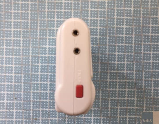
Click to zoom
Application Details
- Equipment Class
- DTS - Digital Transmission System
- Date of Grant
- Jul 11, 2021
- Application Purpose
- Original Equipment
- Date of Application
- Jul 10, 2021
- Equipment Note
- Data Logger
- Frequency Range
- 2402.00000000 - 2480.00000000
- Company
- TandD Corporation
- Country
- Japan
Documents & Files
Document Text
Text extracted from the exhibit documents filed with the FCC. Open a document above to read the original.
Users Manual
Automatic Data Upload to the Cloud The auto-upload function enables TR7 series loggers to automatically upload recorded data to the free cloud storage service "T&D WebStorage Service". The uploaded data is available for viewing from a web browser. The factory default setting is OFF (no auto-upload). Please follow the steps below to change the setting. Please read the "T&D WebStorage Service" License Agreement carefully before making settings. Making Auto-upload Settings indicates your acceptance of this Agreement. Auto-upload of Recorded Data Cloud Wireless/Wired LAN View with a Web Browser Graph Display Download Data Setup Apply Settings • This procedure requires Internet access via wireless LAN. • Old data that exceeds the storage period will be deleted from "T&D WebStorage Service". Please check the details at T&D WebStorage Service License Agreement > Service Details. If you wish to use a static IP address instead of DHCP, make network settings with the software. See reverse side. Making Auto-Upload Settings . Press the <INTERVAL> button twice to display the auto-upload interval. . While is displayed, press-and-hold the <INTERVAL> button until the interval time flashes. . Press <INTERVAL> again to select the interval time. Each press changes the interval as follows: Auto-upload Intervals (): OFF / 1, 2, 5, 10, 15, 20, 30 MIN / 1, 2, 3, 4, 6, 12, 24 HOUR . The interval time will stop flashing and the display will return to the normal measurement mode, confirming that it is set. Ref: Auto-Upload Intervals & Corresponding Estimated Battery Life In general, the shorter the upload interval, the shorter the battery life. Upload Interval min 0 min hr hrs or more Battery LifeAbout 10 days About 2 months About 1 year About 15 months • All estimates are based on operations carried out with a new battery and are in no way a guarantee of actual battery life. • When Auto-upload is used frequently on TR71A, the measurement of the internal sensor may rise by around 0.3° C. Making Wireless LAN Settings To use the WPS feature, make sure to select WPS2-PSK(AES) or disable wireless security in your access point settings. Wireless LAN settings using WPS may not be possible depending on the supported features or settings of your wireless LAN access point. In this case, please make wireless network settings on PC. See reverse side. The following information is required: • Network Name (SSID) • Security (WEP 64bit/128bit, WPA-PSK (TKIP), WPA2-PSK (AES)) • Password (Network Key) . Press the <PWR> and <DISPLAY> buttons together until appears on the LCD screen. . Set your wireless LAN access point to "WPS" mode. For details about Wireless LAN Access Point settings, refer to the user manual for that access point. . When the setup is successfully completed, the mark on the LCD display will turn ON. Checking Connection Status Place the logger in the desired measurement location where Internet access is available. Connection Status Indicators Internet Wireless LAN Access Point Press the <REC/STOP> button to immediately send the recorded data to "T&D WebStorage Service" without waiting for the next transmission. If the transmission is successful, will remain ON after turns OFF. is OFF or blinking: Unable to connect to the wireless network. Try changing the measurement location or adjusting the distance between the logger and the access point, and make the wireless LAN settings in again. is blinking:Internet connection failed. Please check the access point’ s internet connection. Viewing Recorded Data In order to view the recorded data on a web browser, it is necessary to register devices to T&D WebStorage Service in advance. . Access "T&D WebStorage Service" from the web browser. https://www.webstorage-service.com/ . Click [Create Account] to go to the registration page, and follow the direc- tions to complete the registration. If you already have your User ID, go to the next step. . Login by entering the registered User ID and Password. . Click [Devices] in the left menu to open the Device Settings window. . Clicking the [+Device] button will take you to the Add a Device page. . Enter the serial number and registration code* for the target logger, then click [Add]. * The registration code can be found on the supplied Registration Code Label. . After data is sent to either by auto-upload or by pressing the <REC/STOP> button on the logger, the added device and its measurements will appear in the [Data View] window. Troubleshooting Tips If measurements are not displayed: Check the screen of the logger and make sure is ON; If not, press-and-hold <REC/STOP> to start recording. See “Recording Interval Setting above. If the display of measurements is not refreshed: Try making the recording interval shorter. If the recording interval is set to longer than the upload interval, the same measurement is displayed until the next recording occurs and the new data is uploaded. If you lose your registration code label: Open the software "TR7 for Windows" and connect your logger via USB to the computer. The connected logger and its information will appear in the left boxes of the main window. The registration code can be found here. If you wish to save recorded data to PC: Use "T&D Graph" that is available for download from the T&D Website. See on the reverse side. Changing Device Settings It is possible to change device settings by using "T&D WebStorage Service". In the Device Settings window click the [Settings] button to open the settings box. Make the necessary changes and click [Send Settings]. The setting changes will not be actually applied until communication occurs be- tween the logger and "T&D WebStorage Service". By pressing the <REC/STOP> button on the logger, however, settings can be applied immediately. Setting Items which can be set or changed: Device Info Device Name, Group Name, Recording Interval, Recording Mode, Auto- Upload Interval, Time Difference, Temperature Unit, Channel Name Warning Settings Lower Limit,…
Text truncated - open the document above for the full version.
Users Manual
Regarding the Use of Wireless Devices (TR71A, TR72A, TR-75wb) Precautions when Installing Wireless Communication Devices Wireless signals are affected by device placement and interference caused by other environmental factors. The following factors can especially cause an unstable wireless connection, please be mindful of them when deploying devices. Physical Objects: Placing wireless devices far from each other and/or near to obstacles (such as metal objects, concrete, plants, etc.) may lead to a poor wireless connection. Electrical Interference: Placed near cooking equipment such as microwave ovens or communication devices that generate electromagnetic waves. Access Point Capacity: Having many devices connected to one access point simultane- ously. Regarding how many wireless devices can simultaneously connect to an access point and still maintain stable connections, please contact the manufacturer of the wireless access point. Channel Congestion: Using multiple wireless LAN access points with the same communication frequency channel. Change the wireless LAN access point settings to assign a non-overlap- ping channel to each access point. Note: If unstable wireless connection continues, not only will more data transmission errors occur, but battery life will also be shortened. 電波に関するご注意 本製品は電波法に基づく特定小電力無線機器として、技術基準適合証明(利用に関してはお客様の免許申請等が不要)を受けています。 必ず次の点を守ってお使いください。 • 分解・改造をしないでください。 分解・改造は法律で禁止されています。 • 技術基準適合ラベルははがさないでください。 ラベルのないものの使用は禁止されています。 Bluetooth low energy・無線 LAN の電波に関して 本製品の使用周波数帯(2.4GHz)では、電子レンジ等の産業・科学・医療用機器のほか工場の製造ライン等で使用されている移動体識別用の構内無線局(免許を要する 無線局)及び特定小電力無線局(免許を要しない無線局)並びにアマチュア無線局(免許を要する無線局)が運用されています。 1. 本製品を使用する前に、近くで移動体識別用の構内無線局及び特定小電力無線局並びにアマチュア無線局が運用されていないことを確認してください。 2. 万一、本製品から移動体識別用の構内無線局に対して有害な電波干渉の事例が発生した場合には、速やかに使用周波数を変更するか又は電波の発射を停止した上、 下記連絡先にご連絡頂き、混信回避のための処置等(例えば、パーティションの設置など)についてご相談してください。 3. その他、本製品から移動体識別用の特定小電力無線局あるいはアマチュア無線局に対して有害な電波干渉の事例が発生した場合など何かお困りのことが起きたとき は、弊社までお問い合わせください。 連絡先:ティアンドデイオンラインサポート tandd.co.jp/support/ 電波の種類と干渉距離 Bluetooth low energy 無線 LAN(IEEE 802.11b/g/n) 2.4 FH 3 2.4GHz 帯を使用する無線設備を表します。 変調方式が「FH-SS 方式」であることを表します。 想定される与干渉距離が 30m 以下であることを表します。 全帯域を使用し、かつ移動体識別装置の帯域を回避不可であることを表します。 2.4 DS/OF 4 2.4GHz 帯を使用する無線設備を表します。 変調方式が「DS-SS/OFDM 方式」であることを表します。 想定される与干渉距離が 40m 以下であることを表します。 全帯域を使用し、かつ移動体識別装置の帯域を回避可能であることを表します。 사용자 안내문 이 기기는 업무용 환경에서 사용할 목적으로 적합성평가를 받은 기기로서 가정용 환경에서 사용하는 경우 전파간섭의 우려가 있습니다 . 第十二條 經型式認證合格之低功率射頻電機,非經許可,公司、商號或使用者均不得擅自變更頻率、加大功率或變更原設計之特性及功能。 第十四條 低功率射頻電機之使用不得影響飛航安全及干擾合法通信;經發現有干擾現象時,應立即停用,並改善至無干擾時方得繼續使用。 前項合法通信,指依電信法規定作業之無線電通信。低功率射頻電機須忍受合法通信或工業、科學及醫療用電波輻射性電機設備之干擾。 Compliance Information For TR71A / TR72A / TR-75wb <For FCC Model> FCC Statement This device complies with part 15 of the FCC Rules. Operation is subject to the following two conditions: (1) This device may not cause harmful interference, and (2) this device must accept any interference received, including interference that may cause undesired operation. Responsible Party: CAS Dataloggers Chesterland, Ohio https://www.dataloggerinc.com/ This equipment has been tested and found to comply with the limits for a Class B digital device, pursuant to part 15 of the FCC Rules. These limits are designed to provide reasonable protection against harmful interfer- ence in a residential installation. This equipment generates, uses and can radiate radio frequency energy and, if not installed and used in accor- dance with the instructions, may cause harmful interference to radio communications. However, there is no guarantee that interference will not occur in a particular installation. If this equipment does cause harm- ful interference to radio or television reception, which can be determined by turning the equipment off and on, the user is encouraged to try to correct the interference by one or more of the following measures: - Reorient or relocate the receiving antenna. - Increase the separation between the equipment and receiver. -Connect the equipment into an outlet on a circuit different from that to which the receiver is connected. - Consult the dealer or an experienced radio/TV technician for help. Caution: Changes or modifications not expressly approved by the party responsible for compliance could void the user’s authority to operate the equipment. ISED Statement This device contains licence-exempt transmitter(s)/receiver(s) that comply with Innovation, Science and Economic Development Canada’s licence- exempt RSS(s). Operation is subject to the following two conditions: 1. This device may not cause interference. 2. This device must accept any interference, including interference that may cause undesired operation of the device. This digital apparatus complies with CAN ICES-3(B)/NMB-3(B). L’émetteur/récepteur exempt de licence contenu dans le présent appareil est conforme aux CNR d’Innovation, Sciences et Développement économique Canada applicables aux appareils radio exempts de licence. L’exploitation est autorisée aux deux conditions suivantes : 1. L’appareil ne doit pas produire de brouillage; 2. L’appareil doit accepter tout brouillage radioélectrique subi, même si le brouillage est susceptible d’en compromettre le fonctionnement. Cet appareil numérique de la classe B est conforme à la norme NMB-003 du Canada. FCC/ISED Radiation Exposure Statement This equipment complies with FCC/ISED radiation exposure limits set forth for an uncontrolled environment and meets the FCC radio fre- quency (RF) Exposure Guidelines and RSS-102 of the ISED radio frequency (RF) Exposure rules. This equipment should be installed and operated keeping the radiator at least 20cm or more away from person’s body. This transmitter must not be co-located or operated in conjunction with any other antenna or transmitter. Cet équipement est conforme aux limites d’exposition aux rayonnements énoncées pour un environnement non contrôlé et respecte les règles les radioélectriques (RF) de la FCC lignes directrices d’exposition et d’exposition aux fréquences radioélectriques (RF) CNR-102 de l’ISDE. C…
Text truncated - open the document above for the full version.
External Photos
TR71A
External Photos
TR72A
ID Label/Location Info
78 58 26 Serial Label Tamper-proof Pan Head LR Machine Screw(x2) The FCC/CE certification label is attached inside the battery box. After purchasing the data logger, the user will see this label when inserting the batteries. Certification Label TR71A(海外)外観図 21.06.30 Display Panel:Polycarbonate AGC「CARBOGLASS C110C」 Min.thickness:1mm Material Upper Case, Lower Case, Battery Cover:Polycarbonate Mitsubishi Chemical Corporation「Iupilon N5R」 Min.thickness:1mm 設計 製図 検図 承認 内 容 年 月 日担当 株式会社 ティアンドデイ 材料 処理 品名 製品コード 0 0.5 0.5 6 6 30 30 120 120 350 350 1000 ±0.05 ±0.1 ±0.5±0.8 1 2 3 ±0.2±0.3 差 公 度 尺 位 単 Doc.No.TR71A(海外)外観図 1:1 mm
ID Label/Location Info
78 58 26 Serial Label Certification Label The FCC/CE certification label is attached inside the battery box. After purchasing the data logger, the user will see this label when inserting the batteries. Tamper-proof Pan Head LR Machine Screw(x2) TR72A(海外) 外観図 21.06.30 Display Panel:Polycarbonate AGC「CARBOGLASS C110C」 Min.thickness:1mm Material Upper Case, Lower Case, Battery Cover:Polycarbonate Mitsubishi Chemical Corporation「Iupilon N5R」 Min.thickness:1mm 設計 製図 検図 承認 内 容 年 月 日担当 株式会社 ティアンドデイ 材料 処理 品名 製品コード 0 0.5 0.5 6 6 30 30 120 120 350 350 1000 ±0.05 ±0.1 ±0.5±0.8 1 2 3 ±0.2±0.3 差 公 度 尺 位 単 Doc.No.TR72A(海外)外観図 1:1 mm
ID Label/Location Info
25 20 1.4 3.5 1.4 4-R0.2 ・Material:PET 50μ ・Base Color: White ・Text Color: Black ・Surface: Laminated Model: TR71A/TR72A This device complies with part 15 of the FCC Rules. Operation is subject to the following two conditions: (1) This device may not cause harmful interference, and (2) this device must accept any interference received, including interference that may cause undesired operation. The following FCC compliance statement is placed in the user manual as the device is small.
Internal Photos
Board B side Board A side Board A side Inside of LCD
Internal Photos
Board B side Board A side Board A side Inside of LCD
RF Exposure Info
UL Japan, Inc. Ise EMC Lab. 4383-326 Asama-cho, Ise-shi, Mie-ken 516-0021 JAPAN Telephone : +81 596 24 8999 Facsimile : +81 596 24 8124 RF Exposure / MPE Calculation No. : 13753617H Applicant : T&D Corporatio n Type of Equipment : Data Logger Model No. : TR71A FCC ID : SRD50110 T&D Corporation declares that Model: TR71A complies with FCC radiation exposure requirement specified in the FCC Rule 2.1091 (for mobile). RF Exposure Calculations: The following information provides the minimum separation distance for the highest gain antenna provided with the “TR71A“ as calculated from (B) Limits for General Population / Uncontrolled Exposure of TABLE 1- LIMITS FOR MAXIMUM PERMISSIBLE EXPOSURE (MPE) of §1.1310 Radiofrequency radiation exposure limits. [Bluetooth Low Energy part] This calculation is based on the highest EIRP possible from the system, considering maximum power and antenna gain, and considering a 1mW/cm^2 uncontrolled e xp o sur e limit. The F riis fo r mula use d wa s : Where P =0.82 mW (Maximum average output power) Time average was used for the above value in consideration of 6-minutes time-averaging Burst power average was used for the above value in consideration of worst condition. G =1.445 Numerical Antenna gain; equal to 1.6dBi r =20 cm (Separation distance) 0.00024 mW/cm 2 Power Density Result S = 2 4r GP S ×× × = π UL Japan, Inc. Ise EMC Lab. 4383-326 Asama-cho, Ise-shi, Mie-ken 516-0021 JAPAN Telephone : +81 596 24 8999 Facsimile : +81 596 24 8124 Reference: [WLAN Part (Built-in module)] This calculation is based on the highest EIRP possible from the system, considering maximum power and antenna gain, and considering a 1mW/cm^ 2 uncontrolled exposure limit. The Friis formula used was: Where P =100.00 mW (Maximum tune- up peak conducted output power) The value of Conducted power evaluation by the approved module (FCC ID:YOPGS2200M) is use d . G =2.163 Numerical Antenna gain; equal to 3.35dBi r =20 cm (Separation distance) 0.04303 mW/cm 2 Power Density Result S = 2 4r GP S ×× × = π Therefore, if Bluetooth and WLAN 2.4GHz transmit simultaneously, S=0.00024 mW/cm 2 +0.04303 mW/cm 2 =0.04327 mW/cm 2 Even taking into account the tolerance, this device can be satisfied with the limits.
Test Report
Test report No. : 13753617H-A-R1 Page : 1 of 44 Issued date : July 9, 2021 FCC ID : SRD50110 UL Japan, Inc. Ise EMC Lab 4383-326 Asama-cho, Ise-shi, Mie-ken 516-0021 JAPAN Telephone : +81 596 24 8999 Facsimile : +81 596 24 8124 Report Cover Page - 13-EM-F0429 Issue # 19.0 RADIO TEST REPORT Test Report No. : 13753617H-A-R1 Applicant : T&D Corporation Type of EUT : Data Logger Model Number of EUT : TR71A FCC ID : SRD50110 Test regulation : FCC Part 15 Subpart C: 2021 * Bluetooth Low Energy parts Test Result : Complied (Refer to SECTION 3) Date of test: April 12 to June 30, 2021 Representative test engineer: Kiyoshiro Okazaki Engineer Approved by: Takumi Shimada En gineer CERTIFICATE 5107.02 The testing in which "Non-accreditation" is displayed is outside the accreditation scopes in UL Japan, Inc. There is no testing item of "Non-accreditation". 1. This test report shall not be reproduced in full or partial, without the written approval of UL Japan, Inc. 2. The results in this report appl y only to the sample tested. 3. This sample tested is in compliance with the limits of the above re gulation. 4. The test results in this test report are traceable to the national or international standards. 5. This test report must not be used by the customer to claim product certification, approval, or endorsement by the A2LA accreditation bod y. 6. This test report covers Radio technical requirements. It does not cover administrative issues such as Manual or non-Radio test related Requirements. (if applicable) 7. The all test items in this test report are conducted b y UL Japan, Inc. Ise EMC Lab. 8. The opinions and the interpretations to the result of the description in this report are outside scopes where UL Japan has been accredited. 9. The information provide d from the customer for this report is identified in Section 1. 10. This report is a revised version of 13753617H-A. 13753617H-A is replaced with this report. Test report No. : 13753617H-A-R1 Page : 2 of 44 Issued date : July 9, 2021 FCC ID : SRD50110 UL Japan, Inc. Ise EMC Lab. 4383-326 Asama-cho, Ise-shi, Mie-ken 516-0021 JAPAN Telephone : +81 596 24 8999 Facsimile : +81 596 24 8124 REVISION HISTORY Original Test Report No.: 13753617H-A Revision Test report No. Date Page revised Contents - (Original) 13753617H-A June 30, 2021 - - 1 13753617H-A-R1 July 9, 2021 P.13 Correction of title from Radiated emission test to Conducted and Radiated emission tests 1 13753617H-A-R1 July 9, 2021 P.14 Correction of page layout 1 13753617H-A-R1 July 9, 2021 P.16 Correction of IF Bandwidth: AV of Above 1 GHz 1 13753617H-A-R1 July 9, 2021 P.25 Deletion of notes below the table. 1 13753617H-A-R1 July 9, 2021 P.27 Correction of the sentence below the waveform. 1 13753617H-A-R1 July 9, 2021 P.28, 30, 31 Addition of AV detection data of 4th harmonics frequency. Deletion of data of 4th harmonics frequency from table of Peak measurement value with duty c ycle correction factor. 1 13753617H-A-R1 July 9, 2021 P.33 Addition of AV detection point 1 13753617H-A-R1 July 9, 2021 P.39, 40 Addition of *1) to MHA-21, and addition of notes *1) Test report No. : 13753617H-A-R1 Page : 3 of 44 Issued date : July 9, 2021 FCC ID : SRD50110 UL Japan, Inc. Ise EMC Lab. 4383-326 Asama-cho, Ise-shi, Mie-ken 516-0021 JAPAN Telephone : +81 596 24 8999 Facsimile : +81 596 24 8124 Reference: Abbreviations (Including words undescribed in this report) A2LA The American Association for Laboratory Accreditation MCS Modulation and Coding Scheme AC Alternating Current MRA Mutual Recognition Arrangement AFH Adaptive Frequency Hopping N/A Not Applicable AM Amplitude Modulation NIST National Institute of Standards and Technology Amp, AMP Amplifier NS No signal detect. ANSI American National Standards Institute NSA Normalized Site Attenuation Ant, ANT Antenna NVLAP National Voluntary Laboratory Accreditation Program AP Access Point OBW Occupied Band Width ASK Amplitude Shift Keying OFDM Orthogonal Frequency Division Multiplexing Atten., ATT Attenuator P/M Power meter AV Average PCB Printed Circuit Board BPSK Binary Phase-Shift Keying PER Packet Error Rate BR Bluetooth Basic Rate PHY Physical Layer BT Bluetooth PK Peak BT LE Bluetooth Low Energy PN Pseudo random Noise BW BandWidth PRBS Pseudo-Random Bit Sequence Cal Int Calibration Interval PSD Power Spectral Density CCK Complementary Code Keying QAM Quadrature Amplitude Modulation Ch., CH Channel QP Quasi-Peak CISPR Comite International Special des Perturbations Radioelectriques QPSK Quadri-Phase Shift Keying CW Continuous Wave RBW Resolution Band Width DBPSK Differential BPSK RDS Radio Data System DC Direct Current RE Radio Equipment D-factor Distance factor RF Radio Frequency DFS Dynamic Frequency Selection RMS Root Mean Square DQPSK Differential QPSK RSS Radio Standards Specifications DSSS Direct Sequence Spread Spectrum Rx Receiving EDR Enhanced Data Rate SA, S/A Spectrum Analyzer EIRP, e.i.r.p. Equivalent Isotropically Radiated Power SG Signal Generator EMC ElectroMagnetic Compatibility SVSWR Site-Voltage Standing Wave Ratio EMI ElectroMagnetic Interference TR Test Receiver EN European Norm Tx Transmitting ERP, e.r.p. Effective Radiated Power VBW Video BandWidth EU European Union Vert. Vertical EUT Equipment Under Test WLAN Wireless LAN Fac. Factor FCC Federal Communications Commission FHSS Frequency Hopping Spread Spectrum FM Frequency Modulation Freq. Frequency FSK Frequency Shift Keying GFSK Gaussian Frequency-Shift Keying GNSS Global Navigation Satellite System GPS Global Positioning System Hori. Horizontal ICES Interference-Causing Equipment Standard IEC International Electrotechnical Commission IEEE Institute of Electrical and Electronics Engineers IF Intermediate Frequency ILAC International Laboratory Accreditation Conference ISED Innovation, Science and Economic Development Canada ISO International Organization for Standardization JAB Japan Accreditation Board LAN Local Area Network LIMS Laboratory Information Management System Test rep…
Text truncated - open the document above for the full version.
Test Setup Photos
Test report No. : 13753617H-A-R1 Page : 41 of 44 Issued date : July 9, 2021 FCC ID : SRD50110 UL Japan, Inc. Ise EMC Lab. 4383-326 Asama-cho, Ise-shi, Mie-ken 516-0021 JAPAN Telephone : +81 596 24 8999 Facsimile : +81 596 24 8124 APPENDIX 3: Photographs of test setup Conducted Emission Photo 1 Photo 2 Test report No. : 13753617H-A-R1 Page : 42 of 44 Issued date : July 9, 2021 FCC ID : SRD50110 UL Japan, Inc. Ise EMC Lab. 4383-326 Asama-cho, Ise-shi, Mie-ken 516-0021 JAPAN Telephone : +81 596 24 8999 Facsimile : +81 596 24 8124 Radiated Spurious Emission Photo 1 Photo 2 Test report No. : 13753617H-A-R1 Page : 43 of 44 Issued date : July 9, 2021 FCC ID : SRD50110 UL Japan, Inc. Ise EMC Lab. 4383-326 Asama-cho, Ise-shi, Mie-ken 516-0021 JAPAN Telephone : +81 596 24 8999 Facsimile : +81 596 24 8124 Worst Case Position Below 1 GHz (Horizontal: Y-axis/ Vertical: Y-axis) Above 1 GHz (Horizontal: X-axis/ Vertical: Y-axis) X-axis Y-axis Z-axis Test report No. : 13753617H-A-R1 Page : 44 of 44 Issued date : July 9, 2021 FCC ID : SRD50110 UL Japan, Inc. Ise EMC Lab. 4383-326 Asama-cho, Ise-shi, Mie-ken 516-0021 JAPAN Telephone : +81 596 24 8999 Facsimile : +81 596 24 8124 Antenna Terminal Conducted Tests Photo 1 End of Report
Contact Information
Applicant
Ryota Suzuki(Corporate Director)
Technical Contact
UL Japan, Inc.Takumi Shimada
[email protected]81-596-24-8999
4383-326 Asama-cho, Ise-shi · Mie-ken · Japan
Test Firm
UL Japan, Inc.(Ise)Takayuki Shimada
Technical Specifications
| # | Rule Parts | Frequency Range | Power Output |
|---|---|---|---|
| 1 | 15C | 2.40 GHz - 2.48 GHz | 900.00 µW |
Other Applications from TandD Corporation
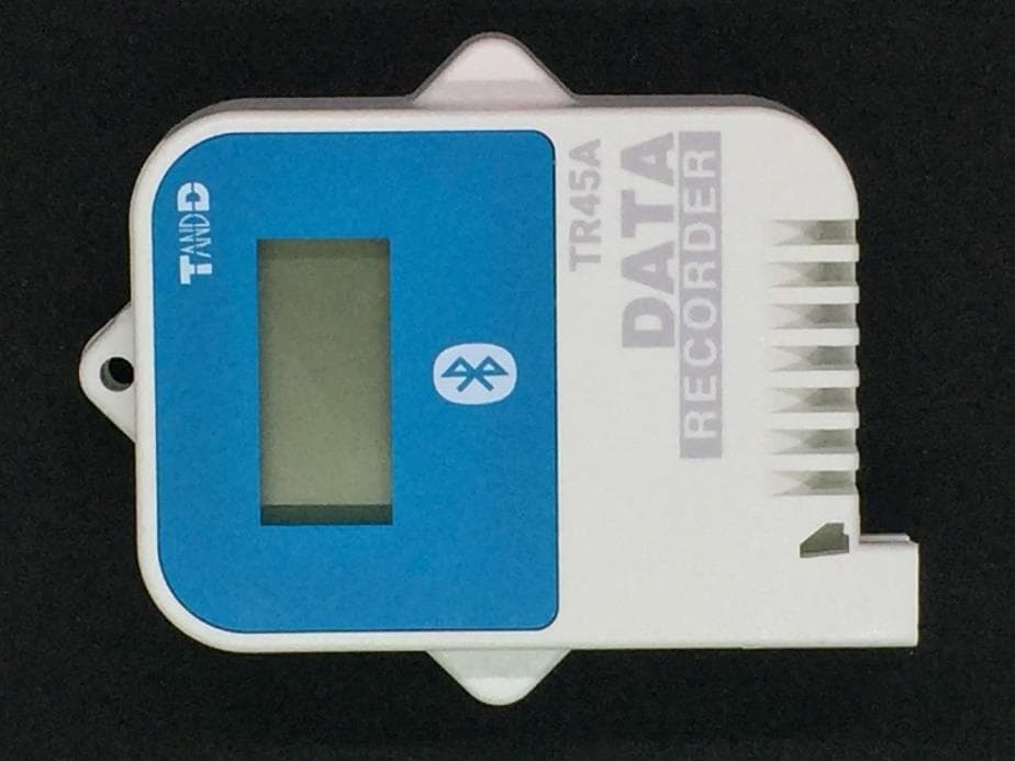
SRD50150
Sep 26, 2024Data Logger
Equipment Class
DTS - Digital Transmission System
SRD50140
Apr 08, 2023Data Logger
Equipment Class
DTS - Digital Transmission System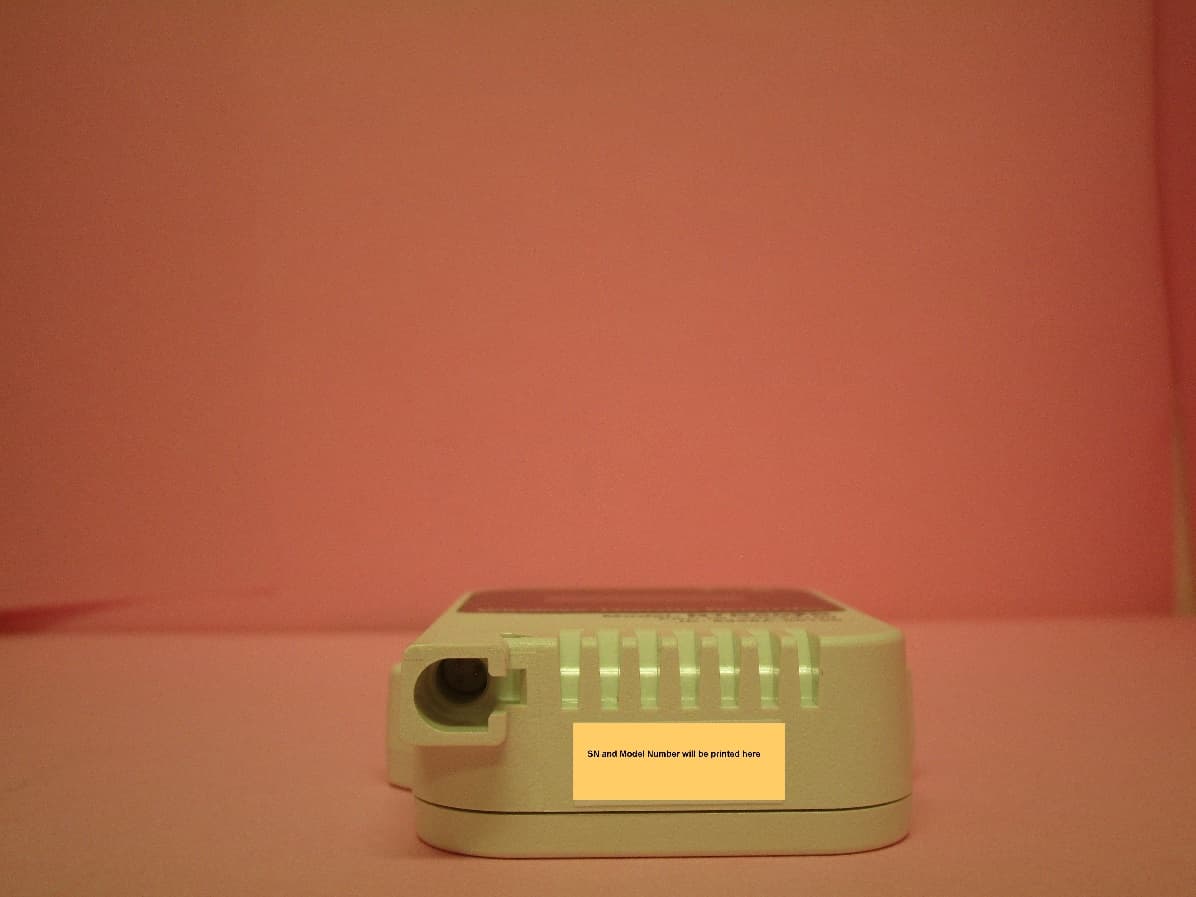
SRD50100
Dec 02, 2020Data Logger Remote Unit
Equipment Class
DTS - Digital Transmission System
SRD10100
Dec 02, 2020Data Logger Base Unit
Equipment Class
DTS - Digital Transmission System
SRD10090
Feb 12, 2015900 MHz BAND TRANSMITTER WITH GSM MODULE
Equipment Class
DSS - Part 15 Spread Spectrum Transmitter