STZSRM9000ACVHF MOBILE TRANSMITTER
Simoco Wireless Solutions Pty Ltd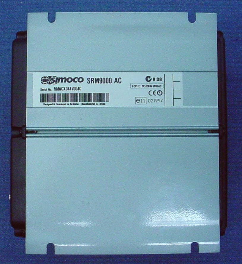
Click to zoom
Application Details
- Equipment Class
- TNB - Licensed Non-Broadcast Station Transmitter
- Date of Grant
- Dec 21, 2004
- Application Purpose
- Original Equipment
- Date of Application
- Dec 21, 2004
- Equipment Note
- VHF MOBILE TRANSMITTER
- Frequency Range
- 150.00000000 - 174.00000000
- Country
- Australia
Documents & Files
Document Text
Text extracted from the exhibit documents filed with the FCC. Open a document above to read the original.
Users Manual
Page i TNM-M-E-0001 Issue 3 SRM 9000 Series FM VHF/UHF Mobile Radio Transceiver SERVICE MANUAL TNM-M-E-0001 ISSUE 3 November 2004 f Page ii TNM-M-E-0001 Issue 3 SRM9000 Series FM VHF/UHF Mobile Ra dio Transceiver TNM-M-E-0001 ~ Iss 3 Page iii TNM-M-E-0001 Issue 3 Declaration The performance figures quoted are subject to normal manufacturing and service tolerances. The right is reserved to alter the equipment described in this manual in the light of future technical development. Copyright All rights reserved. No part of this publication may be reproduced in any form or by any means without the prior permission of TMC Radio. Errors and Omissions The usefulness of this publication depends upon the accuracy and completeness of the information contained within it. Whilst every endeavour has been made to eliminate any errors, some may still exist. It is requested that any errors or omissions noted should be reported to: TMC Radio Pty Ltd. 1270 Ferntree Gully Road Scoresby Vic 3179 Australia Ph: +61 3-9730-3800 (Direct: -3914) Fax: +61 3-9730-3968 Mob: +61 408-160-661 e-mail: [email protected] Page iv TNM-M-E-0001 Issue 3 Document History Issue Date Comments 1 February 2002 Initial issue 2 August 2002 Re-branded to TMC Radio. 3 November 2004 Rev 9 information List of Associated Publications Document No. Description Issue TNM-I-E-0005 SRM9000 Series Installation Instructions 5 TNM-U-E-0012 SRM9020 Trunk Operating Instructions 2 TNM-U-E-0013 SRM9020 PMR Operating Instructions 2 TNM-U-E-0014 SRM9025 PMR Operating Instructions 2 TNM-U-E-0015 SRM9025 Trunk Operating Instructions 2 TNM-U-E-0003 SRM9030 PMR Operating Instructions 2 TNM-U-E-0004 SRM9030 Trunk Operating Instructions 2 TNM-U-E-0020 SRM9030 Brief User Guide 2 TNM-U-E-0042 SRM9010 Brief User Guide 2 TNM-U-E-0043 SRM9020 Brief User Guide 2 TNM-U-E-0044 SRM9025 Brief User Guide 2 Page v TNM-M-E-0001 Issue 3 Warnings and Cautions Caution During disassembly and assembly, refer to Torque Settings in Section 1.7 Caution Preparing the radio for alignment will erase from the radio all customer PMR and Trunking configuration data (channel, signalling information etc). The only data retained by the Alignment Tool is the factory alignment data for the radio (DAC settings for TX power, front-end tuning etc). WARNING SRM9000 radio equipment is to be connected only to 12-volt negative earth systems. In vehicles with a 24-volt supply, an approved 24V/12V converter must be used. The supply must not be taken from a 12V tap on the battery. WARNING To avoid RF injury, do not touch the Antenna when the Transmitter is in use. WARNING Double-fused 12V Supply Leads, Antenna cables and Speaker wiring is to be routed as far away as possible from gas or fuel lines or any electronic control device. The radio transceiver and antenna are to be mounted as far away as possible from these devices and their cabling. Equipment is to be installed, by a competent person, in accordance with the requirements of local radio communications authorities and/or Health and Safety regulations. Post installation checks should be performed to ensure that there is no effect on the operation of the vehicle’s electronics. WARNING Do not operate your radio, without a handsfree kit, whilst driving a vehicle. WARNING Do not operate your radio in an explosive atmosphere. Obey the “Turn Off Two-way Radios” signs where these are posted, e.g. on a petrol station forecourt. WARNING Compliance with RF Energy Exposure Standards: To minimise exposure to RF fields during equipment service and repair, the antenna terminal of the SRM9000 radio should be connected to a suitable non-radiating RF load when the transmitter is in use. Page vi TNM-M-E-0001 Issue 3 GLOSSARY OF TERMS A summary of common radio terms and some other terms used in this document, and their meanings, are given below. 3RP Trunking Signalling Specification relating to trunked networks for shared use. Used primarily for networks in France. ADC Analogue to Digital Converter. AFC Automatic Frequency Control. AGC Automatic Gain Control. Alarm A selcall sequence sent from a subscriber equipment to indicate an Emergency situation. When activated the radio will enter a repeating sequence consisting of an Alarm Live Transmit Time and an Alarm Dead Receive Time. Certain special conditions for the radio may also occur during the alarm - see Conditions during Alarm. A dedicated SFM (trunked system) that is sent by pressing the Alarm Key. ANN Abbreviation for Algorithmic Network Numbering. This is the numbering system where the numbers presented to the radio user can be mapped directly to the MPT1327 PFIX/IDENTs and vice versa by use of a fixed algorithm in combination with some other customisation parameters. See also FPP and MEP. Auto Interrogate An Acknowledge identity sent as a response to an individual reset call. Automatic Power Feature whereby the transmit power is automatically set to a level determined by the level of the received signal. This is used to extend the battery life of a Portable. Automatic Volume Feature whereby the background audio level is monitored and if this is found to be noisy then the volume level is increased to compensate, allowing the user to hear better. Background Hunting The searching for an alternative and 'better' control channel whilst already on a valid control channel. BCAST MPT1327 broadcast message. Used to transmit information about the trunked radio system to radio units. Busy The state of a channel such that: • For a non-signalling channel - if Busy this means that the carrier is above squelch. • For a channel with CTCSS/DCS - if Busy this means a signal is being received with either no CTCSS tone / DCS code or the correct CTCSS tone /DCS code. • For a channel with Selcall - if Busy this means a closed channel where the signal is above squelch. A feature that equates to 'Do Not Disturb' such that the radio will reject all non- emergency calls. This feature can be activated using the Busy key (if ass…
Text truncated - open the document above for the full version.
Users Manual
SRM9030 Mobile Radio Conventional – PMR Operating Instructions TNM-U-E-0003 Issue 7 December 2004 TMC Radio Pty. Ltd. 1270 Ferntree Gully Road Scoresby Victoria, 3179 Australia SRM9030 ~ PMR Mobile Radio User Guide © TMC Radio 2004 i TNM-U-E-0003 Issue 7 ASSOCIATED DOCUMENTATION The following documentation is available for use with the SRM9000 series of products: TNM-I-E-0005 SRM9000 Series Installation Instructions TNM-M-E-0001 SRM9000 Service Manual TNM-U-E-0012 SRM9020 Trunked Operating Instructions TNM-U-E-0013 SRM9020 PMR Operating Instructions TNM-U-E-0014 SRM9025 PMR Operating Instructions TNM-U-E-0015 SRM9025 Trunked Operating Instructions TNM-U-E-0004 SRM9030 Trunked Operating Instructions To order copies of any of the above publications, or any other TMC Radio product, contact TMC Radio on +61 3-9730-3800 or send a Fax on +61 3- 9730-3968. ABOUT THIS DOCUMENT This publication is copyright and no part may be reproduced without prior permission of TMC Radio. Due to our policy of continuous improvement to our products and services, technical specifications and claims, correct at time of publication, may be subject to variation without prior notice. TMC Radio has endeavoured to ensure that the information in this document is fairly and accurately stated, but does not accept liability for any errors or omissions. SRM9030 ~ PMR Mobile Radio User Guide TNM-U-E-0003 Issue 7 Page ii © TMC Radio 2004 RF ENERGY EXPOSURE The SRM9000 series of mobile communications equipment is designed and certified for Occupational Use only in mobile applications and is not approved for use by the General Population. Refer to Appendix B for details on RF Energy Exposure Guidelines and Compliance. SAFETY 1. Do NOT operate your radio, without a handsfree kit, whilst driving a vehicle. 2. Do NOT operate your radio in an explosive atmosphere. Obey the 'Turn Off Two-way Radios' signs where these are posted, e.g. on a petrol station forecourt. 3. Do NOT touch the antenna while the radio is transmitting. 4. Do NOT operate the radio if the antenna has become disconnected or damaged. HINTS FOR USING THE RADIO • When speaking, hold the microphone a few centimeters from your mouth and speak across it, rather than into it. • Keep the length of your conversation to a minimum and replace the microphone on its cradle after use. • When it is possible to move location, avoid making calls from known poor signal-strength areas such as the radio systems fringe areas (limit of range) or from screened or shadowed areas, e.g. an underground car park or underpass. • To avoid unnecessary drain on the vehicle battery, keep the engine running when using the radio for extensive periods of time. SRM9030 ~ PMR Mobile Radio User Guide © TMC Radio 2004 iii TNM-U-E-0003 Issue 7 CONTENTS ASSOCIATED DOCUMENTATION........................................................... I ABOUT THIS DOCUMENT ....................................................................... I RF ENERGY EXPOSURE........................................................................ II SAFETY II HINTS FOR USING THE RADIO ............................................................. II CONTENTS............................................................................................. III 1. INTRODUCTION ................................................................................ 1 1.1 Overview...................................................................................... 1 1.2 Installation................................................................................... 1 2. FRONT PANEL CONTROLS ............................................................. 2 3. MENU SYSTEM.................................................................................. 3 3.1 Menu Navigation ......................................................................... 3 3.2 Default Settings .......................................................................... 4 4. MAIN MENU SCREENS ..................................................................... 5 4.1 Channels Screen......................................................................... 5 4.2 Phonebook Screen ..................................................................... 7 4.3 Status Screen.............................................................................. 8 4.4 Stored Calls Screen.................................................................... 9 4.5 Setup Screen............................................................................... 9 5. COMMON FUNCTIONS AND FACILITIES ...................................... 10 5.1 Switch-On/Switch-Off............................................................... 10 5.1.1 Volume Adjustment........................................................... 10 5.2 Receiving................................................................................... 11 5.3 Transmitting .............................................................................. 12 SRM9030 ~ PMR Mobile Radio User Guide TNM-U-E-0003 Issue 7 Page iv © TMC Radio 2004 5.3.1 VOX Operation ................................................................. 12 5.4 SELCALL Functions................................................................. 13 5.4.1 Receiving a Selcall ........................................................... 13 5.4.2 Sending a Selcall.............................................................. 13 5.4.3 Other Selcall Functions ....................................................13 5.5 Scan Functions......................................................................... 14 5.5.1 Scan Screen.....................................................................15 5.5.2 Scan-Edit Screen............................................................. 16 5.6 MUTE Level Setting .................................................................. 16 5.7 DTMF Operation ....................................................................... 16 5.8 External alert.......................…
Text truncated - open the document above for the full version.
Cover Letter(s)
TCB Response Subject: CS01349 TMC Radio Pty Ltd. FCC ID: SOJSRM9000AC TCB Findings 4. Some of the schematics files are labeled with "UW" as in the previous application, rather than "AC". Please verify this is correct and not a mix up between devices. If there are missing pages please supply them as well. . The SRM9000 schematic set consists of nine sheets. Four of these sheets are frequency band dependent (numbers 4, 5, 6 and 7). The other five sheets (2, 3, 8, 9 and 10) are common to all frequency bands. Our reference set of schematics is based on our SRM900UW version and so the common schematics show the UW designation on those sheets. 5. The alignment procedure shows 1W and 5W power level options. If these will be used and requested to be on the grant of equipment authorization, then at least the RF power output levels must be measured with these power settings. We only request approval for 25W power output. 6. Please specify the DC voltages and currents in the final RF amplifier stage of the device. The DC voltage for the final RF amplifier stage is 13.8 volts nominal. The typical current for this stage is 4.0 amps. 7. Please clarify which document is the "technical product description" mentioned in the confidentiality request. Is this the "Service Manual"? If not please supply the document. The technical product description is contained in Section 3 of the Service Manual. 10. Pg 19 Part 90:FID-25kHz plot makes use of "Mask B". Please clarify why emission "Mask C" has not been used for this operation. Is this mode making use of audio low-pass filter? F1D uses the same audio Low Pass Filter as used for speech. The two FFSK data tones are in-band audio tones of 1200Hz and 1800Hz and are transmitted at 60% of peak system deviation. Hence the use of Mask B and not Mask C. 13. Please specify the RBW and the VBW used for radiated and conducted spurious emissions tests both above and below 1GHz frequency. Measurements have been carried out using a measuring receiver with the following bandwidths Below 1000 MHz: Quasi peak detector with a 120 kHz bandwidth Above 1000 MHz: An average detector with a 1 MHz bandwidth 14. In the transient frequency behavior plots for 12.5 and 25kHz channel spacing, during the "t2" of the turn-on plot, the device appears to exceed the maximum permitted frequency difference limit of 6.25 and 12.5kHz respectively. Also during "t1" of the turn-on and "t3" of the turn-off plots, the frequency difference appears to overshoot the screen and therefore exceed the limit. Please clarify. This transmitter meets the transient frequency requirements for both 12.5 and 25 kHz channel spacing. The plots display both the amplitude and frequency response of the device. The green plot is the frequency response of the transmitter and it is this trace which provides the transient frequency behaviour information. The black trace is the amplitude response of the transmitter and has been provided for information purposes only and should be ignored. In future I will only provide the green trace and not the black one. Hopefully a closer inspection will verify that only very small transient responses were observed as shown by the green trace.
External Photos
EMC Technologies (NZ) Ltd Test Report No 41124.1 Report date: 25 th November 2004 ___________________________________________________________________________________________________________________________________________________________________________________ EMC Technologies (NZ) Ltd STREET ADDRESS - 47 MacKelvie Street, Grey Lynn, Auckland, New Zealand Telephone: +64 9 360 0862 Fax: +64 9 360 0861 POSTAL ADDRESS - PO Box 68 307, Newton, Auckland, New Zealand E-mail: [email protected] Page 36 of 41 This report may not be reproduced except in full Overall Photo Case Front View Case Rear View EMC Technologies (NZ) Ltd Test Report No 41124.1 Report date: 25 th November 2004 ___________________________________________________________________________________________________________________________________________________________________________________ EMC Technologies (NZ) Ltd STREET ADDRESS - 47 MacKelvie Street, Grey Lynn, Auckland, New Zealand Telephone: +64 9 360 0862 Fax: +64 9 360 0861 POSTAL ADDRESS - PO Box 68 307, Newton, Auckland, New Zealand E-mail: [email protected] Page 37 of 41 This report may not be reproduced except in full Case Top Case Bottom
ID Label/Location Info
EMC Technologies (NZ) Ltd Test Report No 41124.1 Report date: 25 th November 2004 ___________________________________________________________________________________________________________________________________________________________________________________ EMC Technologies (NZ) Ltd STREET ADDRESS - 47 MacKelvie Street, Grey Lynn, Auckland, New Zealand Telephone: +64 9 360 0862 Fax: +64 9 360 0861 POSTAL ADDRESS - PO Box 68 307, Newton, Auckland, New Zealand E-mail: [email protected] Page 35 of 41 This report may not be reproduced except in full 10. PHOTOGRAPHS Sample Product Label RF Exposure label location
Internal Photos
EMC Technologies (NZ) Ltd Test Report No 41124.1 Report date: 25 th November 2004 ___________________________________________________________________________________________________________________________________________________________________________________ EMC Technologies (NZ) Ltd STREET ADDRESS - 47 MacKelvie Street, Grey Lynn, Auckland, New Zealand Telephone: +64 9 360 0862 Fax: +64 9 360 0861 POSTAL ADDRESS - PO Box 68 307, Newton, Auckland, New Zealand E-mail: [email protected] Page 38 of 41 This report may not be reproduced except in full PCB Top Layer PCB Bottom Layer EMC Technologies (NZ) Ltd Test Report No 41124.1 Report date: 25 th November 2004 ___________________________________________________________________________________________________________________________________________________________________________________ EMC Technologies (NZ) Ltd STREET ADDRESS - 47 MacKelvie Street, Grey Lynn, Auckland, New Zealand Telephone: +64 9 360 0862 Fax: +64 9 360 0861 POSTAL ADDRESS - PO Box 68 307, Newton, Auckland, New Zealand E-mail: [email protected] Page 39 of 41 This report may not be reproduced except in full Internal photos with the shields removed. Radiated emissions test set up
RF Exposure Info
CHadio FAC}IO PTY LTD TMC Radio Pty Ltd ABN 65 099 952977 www.tmcrodio.com 1270 Ferntree Gully Rd, Scoresby Victorio 31 79, Austroliq Tel: +61 3 9730 3800 Fox: +6] 3 9730 3968 Emoil: [email protected] Ref:TFN0006_0.DOC 9 December 2004 Re: SRM9000 OCCUPATIONAL USE RF EXPOSURE To Whom It Mav Concern: The SRM9000 series of mobile communications equipment is designed for OccupationaU Controlled use only. The SRM9000 series of mobile communications equipment is not intended for use by the General Population. Some examples of applications for which the SRM9000 mobile series could be used include, but are not limited to, the following: Business Commercial activities Emergency services Film and Video Production Forest Products Manufacturers Motor Carriers Petroleum Power Railroad Special Industrial Taxicab Telephone Maintenance Accordingly TMC Radio Pty Ltd is applying for the SRM9000 series of mobile communications equipment to be certified to Occupational/ Controlled exposure limits. Yours Truly, d% Curtis Straus LLC TCB 527 Great Road Littleton. MA 10460 TMC Radio Ptv. Ltd. Form Number: TFN0006_0 Filename: H:\Standards\FCC\FCC_1 01O2\FCC_SRMgOOO_occupational_exposure.doc Page 1 of 1
RF Exposure Info
3513 508 09261 RF Warning Label Printing specification. Prepared Comments Approved Date Rev. AC AC 25/11/04 1.0 Scoresby Australia 3513 508 09261_195_001 Pg. 1 of 1 Form No: TFN0039_1 Specification 3513 508 09261_195_001 3513 508 09261 Label Specification Topcoat : Matte “P-COATED” polymer coating. Base Film : 0.002’’ (0.050mm) silver polyester Adhesive : 0.001’’ (0.025mm) Type E permanent high performance Liner : 0.003’’ (0.075mm) low opacity, white glassine Label Thickness : 0.003’’ (0.075mm) inc adhesive Chemical Resistance Worldmark’s precision thermal transfer coating, when used with specified Info-mark ribbons, yields printed images with extreme resistance to chemicals and fluids such as: 20% & 100% Isopropanol; Stoddart Solvent (mineral spirits); 1,1,1 Trichloroethane; 409 Cleaner; Ambersil & other anti- static cleaners; n-Hexane; Ethanol; Acetone; Methylated Spirits; Gasoline; Abrasive cleaners; Water. (Chemical Resistance properties are based on 30 second rub tests with a cloth soaked in the test fluid, using hard rub pressure of approx 550g [1.2lbs]) Product Approvals UL "Recognised Component" Test Standard UL 969 Marking & Labeling Systems Product Categories: Marking & Labeling System Materials (PGGU2) Marking & Labeling Systems (PGDQ2) Printing Materials (PGJI2) File Numbers: MH17756 (N), MH14238 (N), MH16584 (N) Approval Type: Indoor and Outdoor Use CSA "Accepted Component" Test Standard CAN/CSA - C22.2 No. 0.15 - M90 Adhesive Labels Product Categories: Class 7922 01 Label Stock Class 7921 10 Nameplates Class 7923 01 Printing Systems File Number: 64375 Approval Type: Indoor and Outdoor use. Type A - Heavy Duty "U.L. Recognition" and "CSA Acceptance" is granted on the combination of Info-mark Thermal TransferRibbons and Info-mark Thermal Transfer Labels.
Test Report
EMC Technologies (NZ) Ltd Test Report No 41124.1 Report date: 25 th November 2004 ___________________________________________________________________________________________________________________________________________________________________________________ EMC Technologies (NZ) Ltd STREET ADDRESS - 47 MacKelvie Street, Grey Lynn, Auckland, New Zealand Telephone: +64 9 360 0862 Fax: +64 9 360 0861 POSTAL ADDRESS - PO Box 68 307, Newton, Auckland, New Zealand E-mail: [email protected] Page 1 of 41 This report may not be reproduced except in full TEST REPORT SIMOCO SRM9000 AC VHF Mobile Transceiver tested to the Code of Federal Regulations (CFR) 47 Part 15 – Radio Frequency Devices Part 22 – Public Mobile Services Part 90 –Private Land Mobile Services for TMC Radio Pty Ltd This Test Report is issued with the authority of: ______________________________________ Andrew Cutler - General Manager EMC Technologies (NZ) Ltd Test Report No 41124.1 Report date: 25 th November 2004 ___________________________________________________________________________________________________________________________________________________________________________________ EMC Technologies (NZ) Ltd STREET ADDRESS - 47 MacKelvie Street, Grey Lynn, Auckland, New Zealand Telephone: +64 9 360 0862 Fax: +64 9 360 0861 POSTAL ADDRESS - PO Box 68 307, Newton, Auckland, New Zealand E-mail: [email protected] Page 2 of 41 This report may not be reproduced except in full Table of Contents 1. CLIENT INFORMATION 3 2. DESCRIPTION OF TEST SAMPLE 3 3. COMPLIANCE STATEMENT AND RESULT SUMMARY 4 4. TEST SAMPLE DESCRIPTION 5 5. TEST CONDITIONS 6 5. TEST CONDITIONS 6 6. ATTESTATION 7 7. TEST RESULTS 8 8. TEST EQUIPMENT USED 34 9. ACCREDITATIONS 34 10. PHOTOGRAPHS 35 EMC Technologies (NZ) Ltd Test Report No 41124.1 Report date: 25 th November 2004 ___________________________________________________________________________________________________________________________________________________________________________________ EMC Technologies (NZ) Ltd STREET ADDRESS - 47 MacKelvie Street, Grey Lynn, Auckland, New Zealand Telephone: +64 9 360 0862 Fax: +64 9 360 0861 POSTAL ADDRESS - PO Box 68 307, Newton, Auckland, New Zealand E-mail: [email protected] Page 3 of 41 This report may not be reproduced except in full 1. CLIENT INFORMATION Company Name TMC Radio Pty Ltd Address 1270 Ferntree Gully Road Scoresby City Melbourne Country Australia Contact Mr Robert Stowell 2. DESCRIPTION OF TEST SAMPLE Brand Name SIMOCO Model Number SRM9000 AC Product VHF Mobile Transceiver Manufacturer TMC Radio Pty Ltd Designed in Australia Manufactured in Taiwan Serial Number 5MACX0447004C FCC ID STZSRM9000AC EMC Technologies (NZ) Ltd Test Report No 41124.1 Report date: 25 th November 2004 ___________________________________________________________________________________________________________________________________________________________________________________ EMC Technologies (NZ) Ltd STREET ADDRESS - 47 MacKelvie Street, Grey Lynn, Auckland, New Zealand Telephone: +64 9 360 0862 Fax: +64 9 360 0861 POSTAL ADDRESS - PO Box 68 307, Newton, Auckland, New Zealand E-mail: [email protected] Page 4 of 41 This report may not be reproduced except in full 3. COMPLIANCE STATEMENT AND RESULT SUMMARY The SIMOCO SRM9000 AC VHF Mobile Transceiver complies with the limits defined in 47CFR 15, 47CFR22, 47 CFR Part 90 and 47 CFR Part 2 when tested in- accordance with the test methods described in 47 CFR Part 2. CLAUSE TEST PERFORMED RESULT 2.1041 Measurement procedures Noted 90.203 Certification required Complies 2.1046 RF power output Noted 90.205 Power and antenna height limits Complies 2.1047 Modulation Characteristics 2.1047(a) Low pass filter response Complies 2.1047(b) Modulation limiting characteristics Complies 90.211(a) Modulation characteristics Complies 2.1049 Occupied bandwidth Noted 2.202 Bandwidths Noted 22.357 Emission types Complies 22.359(a) Emission masks Complies 90.207 Types of emissions Complies 90.209 Bandwidth limitations Complies 90.210 Emission masks Complies 2.1051 Spurious emissions at antenna terminals Complies 2.1053 Field strength of spurious radiation Complies 2.1055 Frequency stability Noted 22.355 Frequency tolerance Complies 90.213 Frequency stability Complies 2.1057 Frequency spectrum to be investigated Noted 90.214 Transient frequency behaviour Complies 15.109 Radiated emission limits Complies 15.111 Antenna conducted power measurement Complies 1.1310 Radio frequency radiation exposure limits Complies EMC Technologies (NZ) Ltd Test Report No 41124.1 Report date: 25 th November 2004 ___________________________________________________________________________________________________________________________________________________________________________________ EMC Technologies (NZ) Ltd STREET ADDRESS - 47 MacKelvie Street, Grey Lynn, Auckland, New Zealand Telephone: +64 9 360 0862 Fax: +64 9 360 0861 POSTAL ADDRESS - PO Box 68 307, Newton, Auckland, New Zealand E-mail: [email protected] Page 5 of 41 This report may not be reproduced except in full 4. TEST SAMPLE DESCRIPTION The sample tested has the following specifications: Rated Transmitter Output Power 25.0 Watts (44.0 dBm) Transmitter frequency range 150 – 174 MHz Test frequencies Chl Frequency MHz Power Watts Spacing kHz 1 150.0750 25.0 12.5 2 162.0750 25.0 12.5 3 173.9750 25.0 12.5 4 150.0750 25.0 25.0 5 162.0750 25.0 25.0 6 173.9750 25.0 25.0 Emission Designators / Modes of operation 11k0F3E – Analogue speech 11k0F1D – 1200 baud FFSK 8k10F1E – C4FM digital speech 16k0F3E – Analogue speech 16k0F1D – 1200 baud FFSK Power Supply External DC voltage supply. Typically 13.8 Vdc EMC Technologies (NZ) Ltd Test Report No 41124.1 Report date: 25 th November 2004 ___________________________________________________________________________________________________________________________________________________________________________________ EMC Technologies (NZ) Ltd STREET ADDRESS -…
Text truncated - open the document above for the full version.
Contact Information
Applicant
Barend Gildenhuys(Mr)
Test Firm
EMC Technologies Pty. Ltd.Michael Evans
Technical Specifications
| # | Rule Parts | Frequency Range | Power Output | Emission | Tolerance |
|---|---|---|---|---|---|
| 3 | 22,9 | 150 MHz - 174 MHz | 25 W | 16K0F3E | 5 ppm |
Other Applications from Simoco Wireless Solutions Pty Ltd
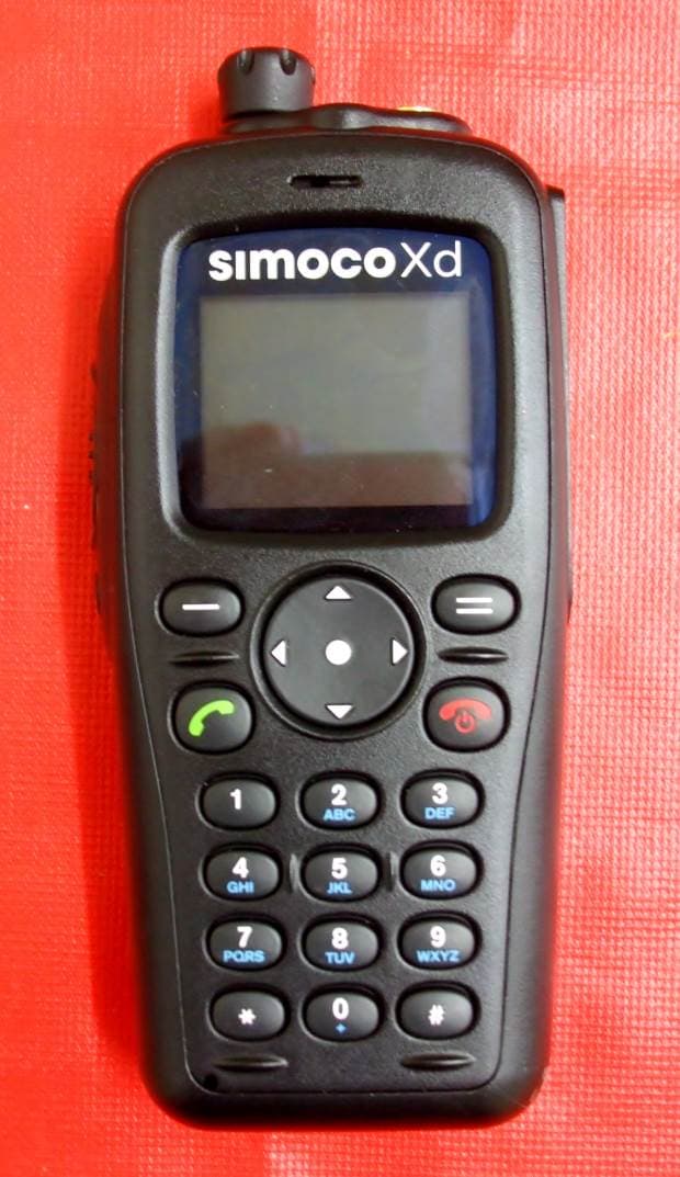
STZSDP600UW
Jun 14, 2015UHF Portable Transceiver
Equipment Class
TNB - Licensed Non-Broadcast Station Transmitter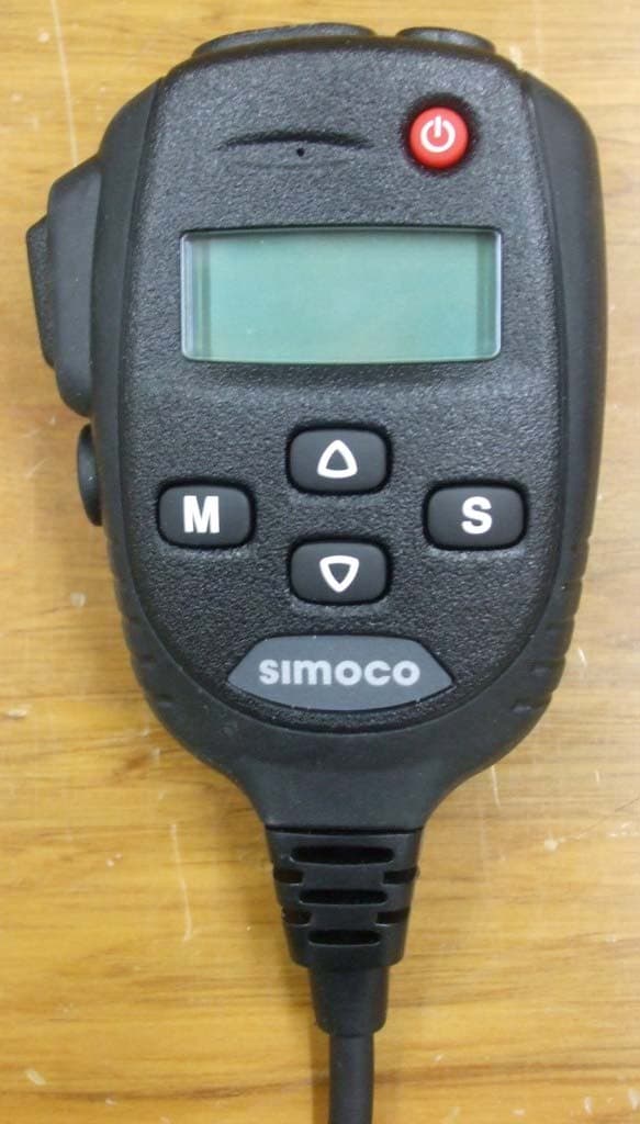
STZSDM600UW
Oct 24, 2013UHF MOBILE TRANSCEIVER
Equipment Class
TNB - Licensed Non-Broadcast Station Transmitter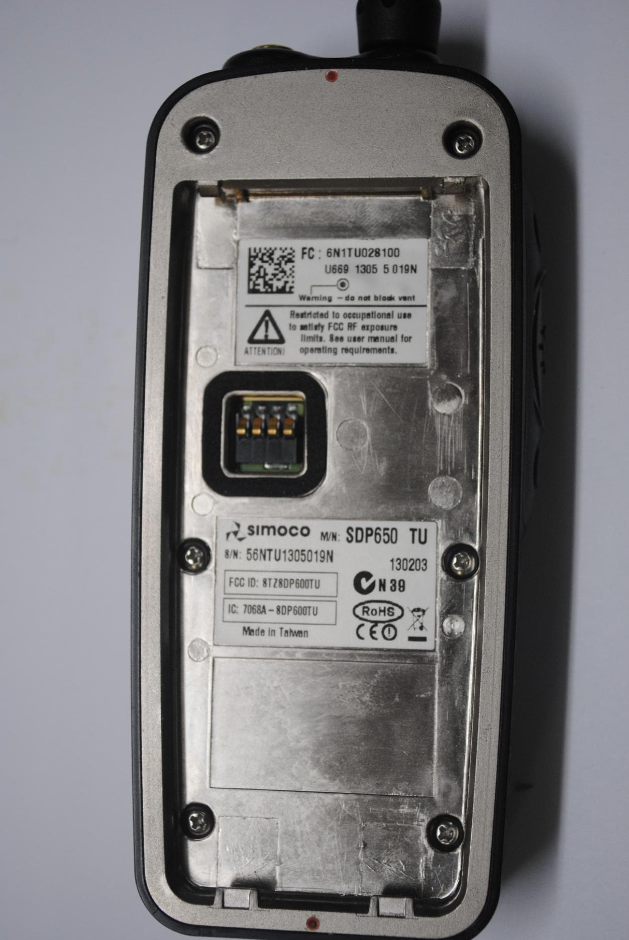
STZSDP600TU
Sep 10, 2013SDP600TU series UHF PMR/DMR Portable Transceiver
Equipment Class
TNF - Licensed Non-Broadcast Transmitter Held to Face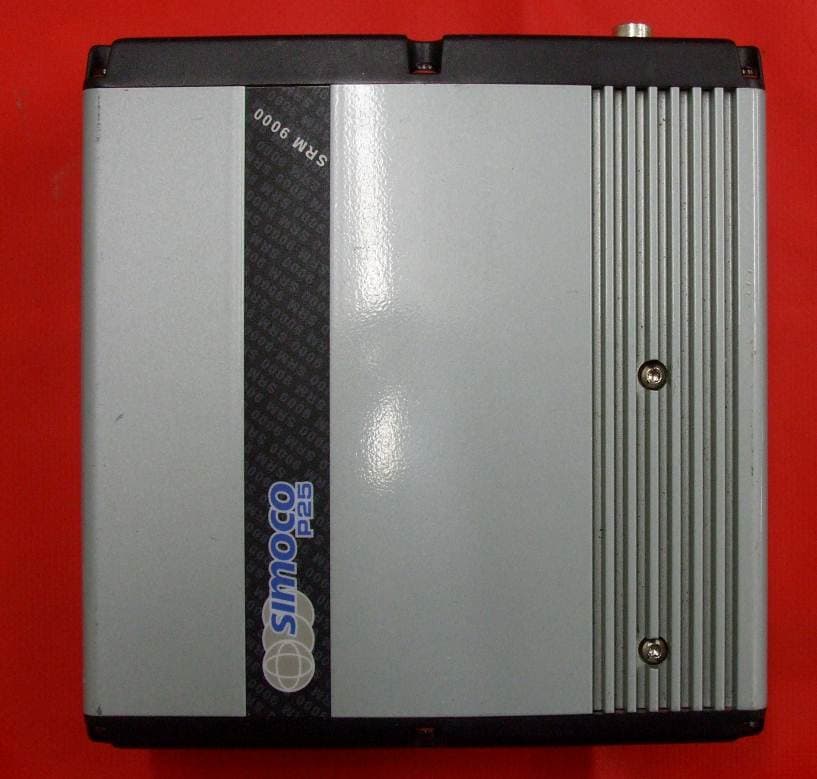
STZSRMA9000TU
Dec 13, 2012UHF MOBILE TRANSCEIVER
Equipment Class
TNB - Licensed Non-Broadcast Station Transmitter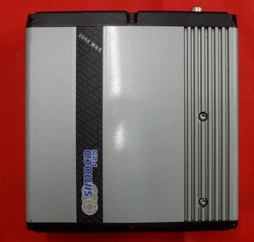
STZSRMA9000AC
Dec 12, 2012VHF MOBILE TRANSCEIVER
Equipment Class
TNB - Licensed Non-Broadcast Station Transmitter