STZSRM9000TUUHF MOBILE TRANSCEIVER
Simoco Wireless Solutions Pty Ltd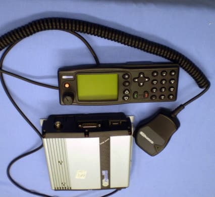
Click to zoom
Application Details
- Equipment Class
- TNB - Licensed Non-Broadcast Station Transmitter
- Date of Grant
- Jul 18, 2007
- Application Purpose
- Original Equipment
- Date of Application
- Jul 17, 2007
- Equipment Note
- UHF MOBILE TRANSCEIVER
- Frequency Range
- 406.10000000 - 480.00000000
- Country
- Australia
Documents & Files
Document Text
Text extracted from the exhibit documents filed with the FCC. Open a document above to read the original.
Users Manual
SRM 9000 Series FM VHF/UHF Mobile Radio Transceiver Revision 9 Hardware SERVICE MANUAL TNM-M-E-0002 ISSUE 1.0 May 2006 ISO9001 Lic.QEC20848 SAI Global SRM9000 Series Mobile Radio Transceiver Rev 9 Hardware TNM - M - E - 0002 ~ Iss 1.0 SRM9000 SERIES SERVICE MANUAL © TMC Radio 2006 page i TNM-U-E-0002 Issue 1 TABLE OF CONTENTS APPENDICES........................................................................................................................................III DECLARATION.....................................................................................................................................IV COPYRIGHT.........................................................................................................................................IV ERRORS AND OMISSIONS..................................................................................................................IV DOCUMENT HISTORY..........................................................................................................................V LIST OF ASSOCIATED PUBLICATIONS..............................................................................................V WARNINGS AND CAUTIONS...............................................................................................................VI 1. INTRODUCTION..........................................................................................................................1 1.1 GENERAL...................................................................................................................................1 1.2 SCOPE......................................................................................................................................1 1.3 DESCRIPTION.............................................................................................................................1 1.4 PRODUCT VARIANTS AND FACILITIES............................................................................................2 1.5 SOFTWARE VERSIONS AND NAMING..............................................................................................5 1.5.1 Filename Structure...........................................................................................................5 1.5.2 Application Code..............................................................................................................5 1.5.3 Software Type Code.........................................................................................................5 1.5.4 Version Number...............................................................................................................7 1.5.5 Exclusions........................................................................................................................7 1.5.6 Displaying Software Versions...........................................................................................7 1.5.7 Automatic Version Upgrade Prompting.............................................................................8 1.5.8 Transceiver SW Description, Start-up and Backup-Software............................................9 1.5.9 Wailing Siren (Boot-up Software Corrupted).....................................................................9 1.6 ADJUSTMENT AND ALIGNMENT.....................................................................................................9 1.7 CHASSIS ASSEMBLY.................................................................................................................10 1.7.1 Torque Settings..............................................................................................................10 1.7.2 Thermal Compound Application.....................................................................................10 1.7.3 Assembly.......................................................................................................................10 1.8 SPECIFICATION.........................................................................................................................10 1.8.1 General..........................................................................................................................10 1.8.2 Transmitter.....................................................................................................................12 1.8.3 Receiver........................................................................................................................13 1.8.4 Signalling.......................................................................................................................14 1.8.4.1 CTCSS...............................................................................................................14 1.8.4.2 FFSK..................................................................................................................15 1.8.4.3 Selcall................................................................................................................15 1.8.4.4 DTMF.................................................................................................................17 1.8.4.5 DCS...................................................................................................................18 1.8.4.6 C4FM.................................................................................................................18 1.8.5 Environmental................................................................................................................19 2. SERVICE PHILOSOPHY............................................................................................................20 2.1 SERVICE CONCEPT...................................................................................................................20 2.2 WARRANTY..............................................................................................................................20 2.2.1 Service Within and Out Of Warranty............…
Text truncated - open the document above for the full version.
Users Manual
SRM9022 Mobile Radio Conventional – PMR Operating Instructions TNM-U-E-0063 Issue 2 March 2007 TMC Radio Pty. Ltd. 1270 Ferntree Gully Road Scoresby Victoria, 3179 Australia ISO9001 Li c.QEC20848 S AI Global SRM9022 ~ PMR MOBILE RADIO USER GUIDE © TMC Radio 2007 page 2 TNM-U-E-0063 Issue 2 ASSOCIATED DOCUMENTATION The following documentation is available for use with the SRM9000 series of products: TNM-I-E-0005 SRM9000 Series Installation Instructions TNM-M-E-0001 SRM9000 Service Manual TNM-U-E-0012 SRM9020 Trunked Operating Instructions TNM-U-E-0013 SRM9020 PMR Operating Instructions TNM-U-E-0004 SRM9030 Trunked Operating Instructions TNM-U-E-0003 SRM9030 PMR Operating Instructions To order copies of any of the above publications, or any other TMC Radio product, contact TMC Radio on +61 3-9730-3800 or send a Fax on +61 3-9730-3968. ABOUT THIS DOCUMENT This publication is copyright and no part may be reproduced without prior permission of TMC Radio. Due to our policy of continuous improvement to our products and services, technical specifications and claims, correct at time of publication, may be subject to variation without prior notice. TMC Radio has endeavoured to ensure that the information in this document is fairly and accurately stated, but does not accept liability for any errors or omissions. SRM9022 ~ PMR MOBILE RADIO USER GUIDE © TMC Radio 2007 page 3 TNM-U-E-0063 Issue 2 SAFETY 1. Do NOT operate your radio, without a handsfree kit, whilst driving a vehicle. 2. Do NOT operate your radio in an explosive atmosphere. Obey the 'Turn Off Two-way Radios' signs where these are posted, e.g. on a petrol station forecourt. 3. Do NOT touch the antenna while the radio is transmitting. 4. Do NOT operate the radio if the antenna has become disconnected or damaged. HINTS FOR USING THE RADIO • When speaking, hold the microphone a few centimeters from your mouth and speak across it, rather than into it. • Keep the length of your conversation to a minimum and replace the microphone on its cradle after use. • When it is possible to move location, avoid making calls from known poor signal- strength areas such as the radio systems fringe areas (limit of range) or from screened or shadowed areas, e.g. an underground car park or underpass. • To avoid unnecessary drain on the vehicle battery, keep the engine running when using the radio for extensive periods of time. SRM9022 ~ PMR MOBILE RADIO USER GUIDE © TMC Radio 2007 page 4 TNM-U-E-0063 Issue 2 CONTENTS 1. INTRODUCTION ................................................................................................. 7 1.1 Overview...................................................................................................... 7 1.2 Installation................................................................................................... 7 1.3 Conventions ................................................................................................ 7 2. FRONT PANEL CONTROLS .............................................................................. 8 3. MENU SYSTEM................................................................................................... 9 3.1 Menu Navigation ......................................................................................... 9 4. MAIN MENU SCREENS .................................................................................... 11 4.1 Channels Screen....................................................................................... 11 4.2 Phonebook Screen................................................................................... 12 4.3 Status Screen............................................................................................ 12 4.4 Send Message Screen .............................................................................. 13 4.5 Stored Calls Screen (Selcall) ................................................................... 14 4.6 Stored Calls Screen (Data Messages)..................................................... 15 4.7 Setup Screen............................................................................................. 16 5. COMMON FUNCTIONS AND FACILITIES ....................................................... 17 5.1 Switch-On/Switch-Off ............................................................................... 17 5.1.1 Volume Adjustment ................................................................................. 17 5.2 Receiving................................................................................................... 17 5.3 Transmitting .............................................................................................. 18 5.4 SELCALL Functions ................................................................................. 19 5.4.1 Receiving a Selcall .................................................................................. 19 5.4.2 Sending a Selcall .................................................................................... 19 5.4.3 Other Selcall Functions ........................................................................... 19 5.5 Scan Functions ......................................................................................... 20 5.5.1 Scan Screen............................................................................................ 20 5.5.2 Scan-Edit Screen.................................................................................... 21 5.6 DTMF Operation........................................................................................ 22 5.7 External alert ............................................................................................. 22 5.8 Auxiliary Output ........................................................................................ 22 6. SETUP ............................................................................................................... 23 6.1 Setup Sub-Menus .....................................................…
Text truncated - open the document above for the full version.
Cover Letter(s)
Confidentiality is specifically requested for the following documents: - Schematics SRM9100TU Schematics.pdf - Technical Product Description SRM9100TU Operational Description.pdf - Block Diagram SRM9100TU Block Diagram.pdf - Part list SRM9100TU Part list.pdf
Cover Letter(s)
lIlGHadio R.: SRMgoofiU FCC Equlpn nt AppbEl To wlon It Mly Cdceb: Th. followilg iDfom.rim b b b. hcld conEderti pumdt ol47 CFR Prn O tO 459 ard setion 552OX4) of the FEdd ofln)mtion Act, b@u$ de inlmrtid rftvided cdtii4tldes@tsddi5pblrieidy. Md. public, &. infomliotr niEll he ui€d to ln. {ti$ilv6l!s. ofthe.ppliMt h lnc mtct pLe. . T€trial Prduct Deriprion Fed€El Co,mni@tbB comhd@ TMC Rldlo Plv. LlrL
Cover Letter(s)
?A-^u- I GHadio To Wl@Il Mr)r Cdml TIF Glquctry of oFalim of t[c SRM9O()oIU Dobile Eitio omt h. [email protected] hy th. opdtor lo hdmn @ AqFd"is 06.r tb6 6c poglm.d bt @ice d dinrellM D.MmI. Tbl SRM9ooOT!' DobiL idio quic thc op€iding 6!q!@i6 ro b. Drcsmsd lhdrr! r[. e of e qEi!.1 d.vic. only .hiLtL !o @i@ or aiotel!!@ R.: SRfgomIU a7 CFR Ptrt 3056l.) ComCh.6 !49.&4s!$-I&
Cover Letter(s)
.)ynr.g^rpsip Ref:TFN.DOC R.: SRM9000iU 47 CFR Pan 90,2030(3) Comprrancd 24 M.y 2007 To Wton n May Concem: Thk is to di8 that lhc rcquimmb or4? CFR Pln 90.203(jX3) spernn eftciency st' .rdofon voie chdnel per l2.5kHz ofchatret bind*idrh are net by rfie SRM9OOOTU mobile ndio as dnolMted by fie bts conducred on dE sple E lio povided (l lkOF3E nission). Alidiliondly in this sinple, dre C4FM ,lala Gic is in iccodme with TL{ I02, lh.l ts 9600 btu D€. second in a l2.5kHz chrml bddNidrh. lhftfoE lhe SRM9000TU hnmine{i dai. disnes $e ftquirenent 014300 bis pd sond p€r 6.25kfi2 ofctunel bandwidth (3K10FlE emission). 1!4q&4s-tq.L!4
External Photos
EMC Technologies (NZ) Ltd Test Report No 70543.1 Report date: 29th June 2007 _________________________________________________________________________________________________________________________________________________ EMC Technologies (NZ) Ltd STREET ADDRESS - 47 MacKelvie Street, Grey Lynn, Auckland, NZ Phone: +64 9 360 0862 Fax: +64 9 360 0861 POSTAL ADDRESS - PO Box 68 307, Newton, Auckland, New Zealand E-mail: [email protected] Page 38 of 43 This report may not be reproduced except in full External Views EMC Technologies (NZ) Ltd Test Report No 70543.1 Report date: 29th June 2007 _________________________________________________________________________________________________________________________________________________ EMC Technologies (NZ) Ltd STREET ADDRESS - 47 MacKelvie Street, Grey Lynn, Auckland, NZ Phone: +64 9 360 0862 Fax: +64 9 360 0861 POSTAL ADDRESS - PO Box 68 307, Newton, Auckland, New Zealand E-mail: [email protected] Page 39 of 43 This report may not be reproduced except in full External Overview
ID Label/Location Info
EMC Technologies (NZ) Ltd Test Report No 70543.1 Report date: 29th June 2007 _________________________________________________________________________________________________________________________________________________ EMC Technologies (NZ) Ltd STREET ADDRESS - 47 MacKelvie Street, Grey Lynn, Auckland, NZ Phone: +64 9 360 0862 Fax: +64 9 360 0861 POSTAL ADDRESS - PO Box 68 307, Newton, Auckland, New Zealand E-mail: [email protected] Page 37 of 43 This report may not be reproduced except in full 10. PHOTOGRAPH (S) Sample product label Label on Product
Internal Photos
EMC Technologies (NZ) Ltd Test Report No 70543.1 Report date: 29th June 2007 _________________________________________________________________________________________________________________________________________________ EMC Technologies (NZ) Ltd STREET ADDRESS - 47 MacKelvie Street, Grey Lynn, Auckland, NZ Phone: +64 9 360 0862 Fax: +64 9 360 0861 POSTAL ADDRESS - PO Box 68 307, Newton, Auckland, New Zealand E-mail: [email protected] Page 40 of 43 This report may not be reproduced except in full Internal Views EMC Technologies (NZ) Ltd Test Report No 70543.1 Report date: 29th June 2007 _________________________________________________________________________________________________________________________________________________ EMC Technologies (NZ) Ltd STREET ADDRESS - 47 MacKelvie Street, Grey Lynn, Auckland, NZ Phone: +64 9 360 0862 Fax: +64 9 360 0861 POSTAL ADDRESS - PO Box 68 307, Newton, Auckland, New Zealand E-mail: [email protected] Page 41 of 43 This report may not be reproduced except in full
Parts List/Tune Up Info
SRM9000 ALIGNMENT TNM-M-E-0019 Issue 1 Page 1 of 13 ALIGNMENT (LEVEL 3 SERVICE ONLY) This procedure is applicable to all versions of SRM9000 mobile transceivers. If the radio contains customer configuration data that must be retained, you must first use the SRM/SRP Personality Programmer (FPP) software to read all radio configuration files and save them on to alternative media before commencing the alignment procedure. When the Alignment is completed, use the FPP software to retrieve this stored data and write it back to the radio. It is preferred that the radio remain installed in its aluminium extruded case throughout this alignment procedure. If the radio is to be aligned when removed from the case, a temporary heat sink must be fitted under the Transmitter PA module and the receiver output must be kept below 100mW. Note. Final Tx power adjustments must be performed with the radio board installed in the chassis. TEST EQUIPMENT 1. Radio transceiver test set CMT, 52/82 or similar. Note. For alternative equipment, the Mod Balance test requires internal DC coupling between the demodulated signal and demodulation output connector. 2. Variable DC power supply 10.8V to 16.3V current limited to 7 amps 3. Oscilloscope 20 MHz bandwidth minimum 4. SRM9000 Programming & Alignment Breakout Box As detailed in Figure 0 5. SRM9000 Speaker O/P Breakout Box As detailed in Figure 1 6. Personal Computer 486 DX 66 or better. Operating system Windows 95 or later. Minimum RAM - 16MB. 5MB free hard disk space. Floppy drive - 1.44MB. Mouse and serial port required 7. SRM/SRP Alignment Tool Computer Software file 8. SRM/SRP Field Personality Programmer (FPP) Computer Software file Caution Preparing the radio for alignment will erase from the radio all customer PMR and Trunking configuration data (channel, signalling information etc). The only data retained by the Alignment Tool is the factory alignment data for the radio (DAC settings for Tx power, front-end tuning, etc). Using the Alignment Tool will allow changes to the original factory alignment and will invalidate all warranties and guarantees unless performed by an authorised level 3 service centre. SRM9000 ALIGNMENT TNM-M-E-0019 Issue 1 Page 2 of 13 Black Red Ye l lo w Blue Brown Orange Green(4) White (8) (Not Used) + 470E White Green Mic Audio in Mic Ground Ground Handset AF Output 13.8V Switched On/Off Rx Data Tx Data 8 4 7 6 5 3 2 1 RJ45 PRM80 Programming Cable P/N 9525-001-00016 BNC (F) Connector 22uF to 47uF Tant. or Elect DB25 Access and modify cable as shown 9000_49/2 2 5 - 9 W a y A d a p t o r PC To SRM9000 S1 AF Generator R Figure 0 SRM9000 Programming & Alignment Breakout Box . . . To SRM9000 P2 Pins 6 & 13 R = Audio power Load (set as appropriate) or Resistor 4R 4W for ½ Bridge Speaker option Resistor 8R 12W for full Bridge Speaker option 600R 1:1 Line Matching Transformer To Noise & Distortion Meter & Oscilloscope 9000_49/3b R T1 Figure 1 SRM9000 Speaker Output Breakout Box SRM9000 ALIGNMENT TNM-M-E-0019 Issue 1 Page 3 of 13 TEST SET-UP Figure 2 Test Set-up 1. Connect the radio to the test equipment as shown in Figure 4-3. 2. Switch on the DC Power Supply. 7 6 5 4 3 2 1 8 15 14 13 12 11 10 9 SRM9000 P2 (DB15M) PC SRM9000 Programming and Alignment Breakout Box S5 Antenna Skt S1 RJ45 AF Generator 13.8V DC Power Supply CRO 9000_49 + - Radio Transceiver Te st Set Noise & Distortion Meter SRM9000 Speaker O/P Breakout Box Coax (<200 mm) SRM9000 ALIGNMENT TNM-M-E-0019 Issue 1 Page 4 of 13 COMMS Set up 1. Copy the SRM9000 Alignment Tool Computer Software file to the PC hard drive and run the program The Alignment Tool Opening Menu is displayed. 2. Go to the Options menu and choose Comms Setup. 3. The Comms Setup dialogue box is displayed. Select the Comms Port setting appropriate to the configuration of your PC and choose 9OK. (Usually COM1) SRM9000 ALIGNMENT TNM-M-E-0019 Issue 1 Page 5 of 13 Radio Preparation Radio parameters are to be aligned sequentially as detailed in this procedure. 1. At the Opening Menu, select the Align Menu and choose Prepare/Read Radio. 2. The WARNING is displayed. Choose N o if you want to save the configuration and use the FPP software to read and save the data to a file. Choose Y es if you want to proceed and go to step 3. 3. The radio alignment data is read (indicated by percentage bar) and stored. The test alignment data is downloaded into the radio. Note: In test alignment mode the radio is configured only for 12.5 kHz channel spacing, therefore all alignment is carried out at 12.5 kHz settings unless otherwise specified. When the radio is configured with the FPP for other channel spacings, the deviation related levels are calculated on a per channel basis by the radio software. SRM9000 ALIGNMENT TNM-M-E-0019 Issue 1 Page 6 of 13 Alignment Procedure Radio alignment must be done in the sequence detailed in the following paragraphs. This alignment assumes that the radio is functioning normally. VCO DAC Alignment 1. Select the VCO DAC page. 2. Select Auto Align. The Synth DAC Rx slider will automatically adjust its value for each receiver alignment frequency to set the VCO loop filter value between 140 and 150. 3. Select PTT and then select Auto Align. The Synth DAC Tx slider will automatically adjust its value for each transmitter alignment frequency to set the VCO loop filter value between 140 and 150. SRM9000 ALIGNMENT TNM-M-E-0019 Issue 1 Page 7 of 13 TCXO (Radio Netting Adjustment) 1. Select the Mute/TCXO page. 2. Select PTT. 3. Adjust the TCXO slider to ensure that the transmit frequency error is within 50Hz for the selected channel (to be measured on the RF Test Set frequency counter). SRM9000 ALIGNMENT TNM-M-E-0019 Issue 1 Page 8 of 13 Rx Front End 1. Ensure that the TCX0 Alignment has been done before proceeding with this section. 2. Select the Rx Front End Page. 3. Select Open Mute. 4. Set the Volume slider to 15. Speaker audio should now be visible on the Scope. If required readjust the Volume slider to a sui…
Text truncated - open the document above for the full version.
RF Exposure Info
EMC Technologies (NZ) Ltd Test Report No 70543.1 Report date: 29th June 2007 _________________________________________________________________________________________________________________________________________________ EMC Technologies (NZ) Ltd STREET ADDRESS - 47 MacKelvie Street, Grey Lynn, Auckland, NZ Phone: +64 9 360 0862 Fax: +64 9 360 0861 POSTAL ADDRESS - PO Box 68 307, Newton, Auckland, New Zealand E-mail: [email protected] Page 35 of 43 This report may not be reproduced except in full Radio Frequency Hazard Information As per Section 1.1310 and Section 2.1091 certification of this transmitter is sought using the Controlled / Occupational exposure limits as detailed in OST/OET Bulletin Number 65 as a power of 25 watts is to be used in a mobile environment where the use of the transmitter will be employment related. Calculations have been made using the General Public/Uncontrolled Exposure limits. Minimum safe distances have been calculated below. Power density, W/m 2 = E 2 /3770 - Occupational / Controlled Exposure limit will be 1.46 mW/cm 2 (f/300 = 440 MHz/300) - General Population / Uncontrolled exposure limit will be 0.29 mW/cm 2 (f/1500 = 440 MHz/1500) The minimum distance from the antenna at which the MPE is met is calculated from the equation relating field strength in V/m, transmit power in watts, transmit antenna gain, transmitter duty cycle and separation distance in metres: E, V/m = (√ (30 * P * G)) / d Controlled Uncontrolled E = 1.46 mW/cm 2 = E 2 /3770 E = 0.29 mW/cm 2 = E 2 /3770 E= √1.46*3770 E= √0.29*3770 E = 74.2 V/m E = 33.1 V/m The rated maximum transmitter power = 25 watts. Transmitter operated using a quarter wave whip antenna with a gain of 2.15 dBi (1.64). The transmitter is a push to talk device that would typically be used with a duty cycle of 50% in a 6 minute period or a 30 minute period. Controlled Uncontrolled d = √ (30 * P * G*DC) / E d = √ (30 * 25.0 * 1.64 * 0.5) / 74.2 d = √ (30 * 25.0 * 1.64 * 0.5) / 33.1 d = 0.3342 metres or 34 cm d = 0.7492 metres or 75 cm Result: Complies
Test Report
EMC Technologies (NZ) Ltd Test Report No 70543.1a Report date: 7th July 2007 _________________________________________________________________________________________________________________________________________________ EMC Technologies (NZ) Ltd STREET ADDRESS - 47 MacKelvie Street, Grey Lynn, Auckland, NZ Phone: +64 9 360 0862 Fax: +64 9 360 0861 POSTAL ADDRESS - PO Box 68 307, Newton, Auckland, New Zealand E-mail: [email protected] Page 1 of 43 This report may not be reproduced except in full TEST REPORT SIMOCO SRM9000TU / MACOM M3300 UHF Mobile Transceiver tested to the Code of Federal Regulations (CFR) 47 Part 90 –Private Land Mobile Services Part 22 – Public Mobile Services Part 15 – Radio Frequency Device for TMC Radio Pty Ltd This Test Report is issued with the authority of: ______________________________________ Andrew Cutler - General Manager EMC Technologies (NZ) Ltd Test Report No 70543.1a Report date: 7th July 2007 _________________________________________________________________________________________________________________________________________________ EMC Technologies (NZ) Ltd STREET ADDRESS - 47 MacKelvie Street, Grey Lynn, Auckland, NZ Phone: +64 9 360 0862 Fax: +64 9 360 0861 POSTAL ADDRESS - PO Box 68 307, Newton, Auckland, New Zealand E-mail: [email protected] Page 2 of 43 This report may not be reproduced except in full Table of Contents 1. CLIENT INFORMATION 3 2. DESCRIPTION OF TEST SAMPLE 3 3. COMPLIANCE STATEMENT AND RESULT SUMMARY 4 4. TEST SAMPLE DESCRIPTION 5 5. TEST CONDITIONS 6 6. ATTESTATION 7 7. TEST RESULTS 8 8. TEST EQUIPMENT USED 36 9. ACCREDITATIONS 36 10. PHOTOGRAPH (S) 37 EMC Technologies (NZ) Ltd Test Report No 70543.1a Report date: 7th July 2007 _________________________________________________________________________________________________________________________________________________ EMC Technologies (NZ) Ltd STREET ADDRESS - 47 MacKelvie Street, Grey Lynn, Auckland, NZ Phone: +64 9 360 0862 Fax: +64 9 360 0861 POSTAL ADDRESS - PO Box 68 307, Newton, Auckland, New Zealand E-mail: [email protected] Page 3 of 43 This report may not be reproduced except in full 1. CLIENT INFORMATION Company Name TMC Radio Pty Ltd Address 1270 Ferntree Gully Road Scoresby City Victoria, 3179 Country Australia Contact Mr Robert Stowell 2. DESCRIPTION OF TEST SAMPLE Brand Name SIMOCO / MACOM Model Number SRM9000TU / M3300 Product UHF Mobile Transceiver Manufacturer TMC Radio Pty Ltd Designed in Australia Manufactured in Taiwan Serial Number ARTUX0710212K FCC ID STZSRM9100TU EMC Technologies (NZ) Ltd Test Report No 70543.1a Report date: 7th July 2007 _________________________________________________________________________________________________________________________________________________ EMC Technologies (NZ) Ltd STREET ADDRESS - 47 MacKelvie Street, Grey Lynn, Auckland, NZ Phone: +64 9 360 0862 Fax: +64 9 360 0861 POSTAL ADDRESS - PO Box 68 307, Newton, Auckland, New Zealand E-mail: [email protected] Page 4 of 43 This report may not be reproduced except in full 3. COMPLIANCE STATEMENT & RESULT SUMMARY The SIMOCO SRM9000TU / MACOM M3300 UHF Mobile Transceiver complies with the limits defined in 47CFR 15, 47CFR22, 47 CFR Part 90 and 47 CFR Part 2 when tested in-accordance with the test methods described in 47 CFR Part 2. CLAUSE TEST PERFORMED RESULT 90.203 Certification required Complies 2.1046 RF power output Noted 90.205 Power and antenna height limits Complies 2.1047 Modulation Characteristics 2.1047(a) Low pass filter response Complies 2.1047(b) Modulation limiting characteristics Complies 90.211(a) Modulation characteristics Complies 2.1049 Occupied bandwidth Noted 2.202 Bandwidths Noted 22.357 Emission types Complies 22.359(a) Emission masks Complies 90.207 Types of emissions Complies 90.209 Bandwidth limitations Complies 90.210 Emission masks Complies 2.1051 Spurious emissions at antenna terminals Complies 2.1053 Field strength of spurious radiation Complies 2.1055 Frequency stability Noted 22.355 Frequency tolerance Complies 90.213 Frequency stability Complies 90.214 Transient frequency behaviour Complies 15.109 Radiated emission limits Complies 15.111 Antenna conducted power measurement Complies EMC Technologies (NZ) Ltd Test Report No 70543.1a Report date: 7th July 2007 _________________________________________________________________________________________________________________________________________________ EMC Technologies (NZ) Ltd STREET ADDRESS - 47 MacKelvie Street, Grey Lynn, Auckland, NZ Phone: +64 9 360 0862 Fax: +64 9 360 0861 POSTAL ADDRESS - PO Box 68 307, Newton, Auckland, New Zealand E-mail: [email protected] Page 5 of 43 This report may not be reproduced except in full 4. TEST SAMPLE DESCRIPTION The sample tested has the following specifications: Rated Transmitter Output Power 25.0 Watts (44 dBm) Transmitter frequency range 400-480 MHz Test frequencies Chl Frequency MHz Power Watts Spacing kHz 1 400.075 25 12.5 2 440.075 25 12.5 3 479.975 25 12.5 4 400.075 25 25.0 5 440.075 25 25.0 6 479.975 25 25.0 FCC Bands Part 90: 421- 512 MHz Part 22: 50-450 MHz, 450-512 MHz Emission Designators / Modes of operation 11k0F3E – Analogue speech 11k0F1D – 1200 baud FFSK 8k10F1E – C4FM digital speech 16k0F3E – Analogue speech 16k0F1D – 1200 baud FFSK Power Supply DC voltage supply. Typically 13.8 Vdc battery supply EMC Technologies (NZ) Ltd Test Report No 70543.1a Report date: 7th July 2007 _________________________________________________________________________________________________________________________________________________ EMC Technologies (NZ) Ltd STREET ADDRESS - 47 MacKelvie Street, Grey Lynn…
Text truncated - open the document above for the full version.
Contact Information
Applicant
Barend Gildenhuys(Mr)
Test Firm
EMC Technologies NZ Ltd.Andrew Cutler
Technical Specifications
| # | Rule Parts | Frequency Range | Power Output | Emission | Tolerance |
|---|---|---|---|---|---|
| 5 | 22,9 | 406.1 MHz - 480 MHz | 25 W | 16K0F1D | 2.5 ppm |
Other Applications from Simoco Wireless Solutions Pty Ltd
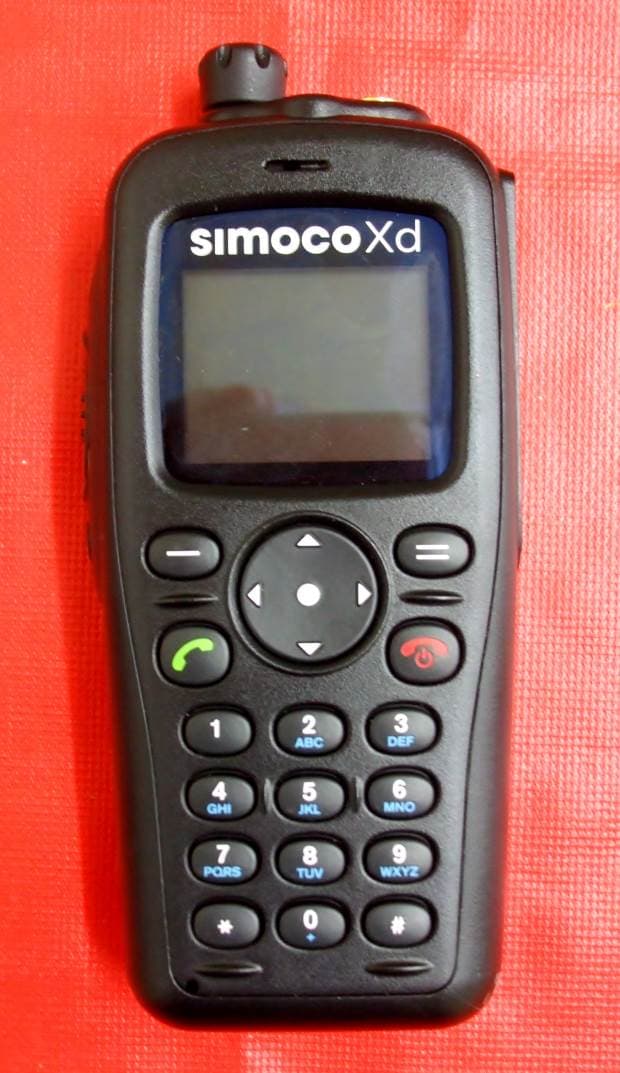
STZSDP600UW
Jun 14, 2015UHF Portable Transceiver
Equipment Class
TNB - Licensed Non-Broadcast Station Transmitter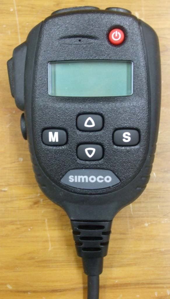
STZSDM600UW
Oct 24, 2013UHF MOBILE TRANSCEIVER
Equipment Class
TNB - Licensed Non-Broadcast Station Transmitter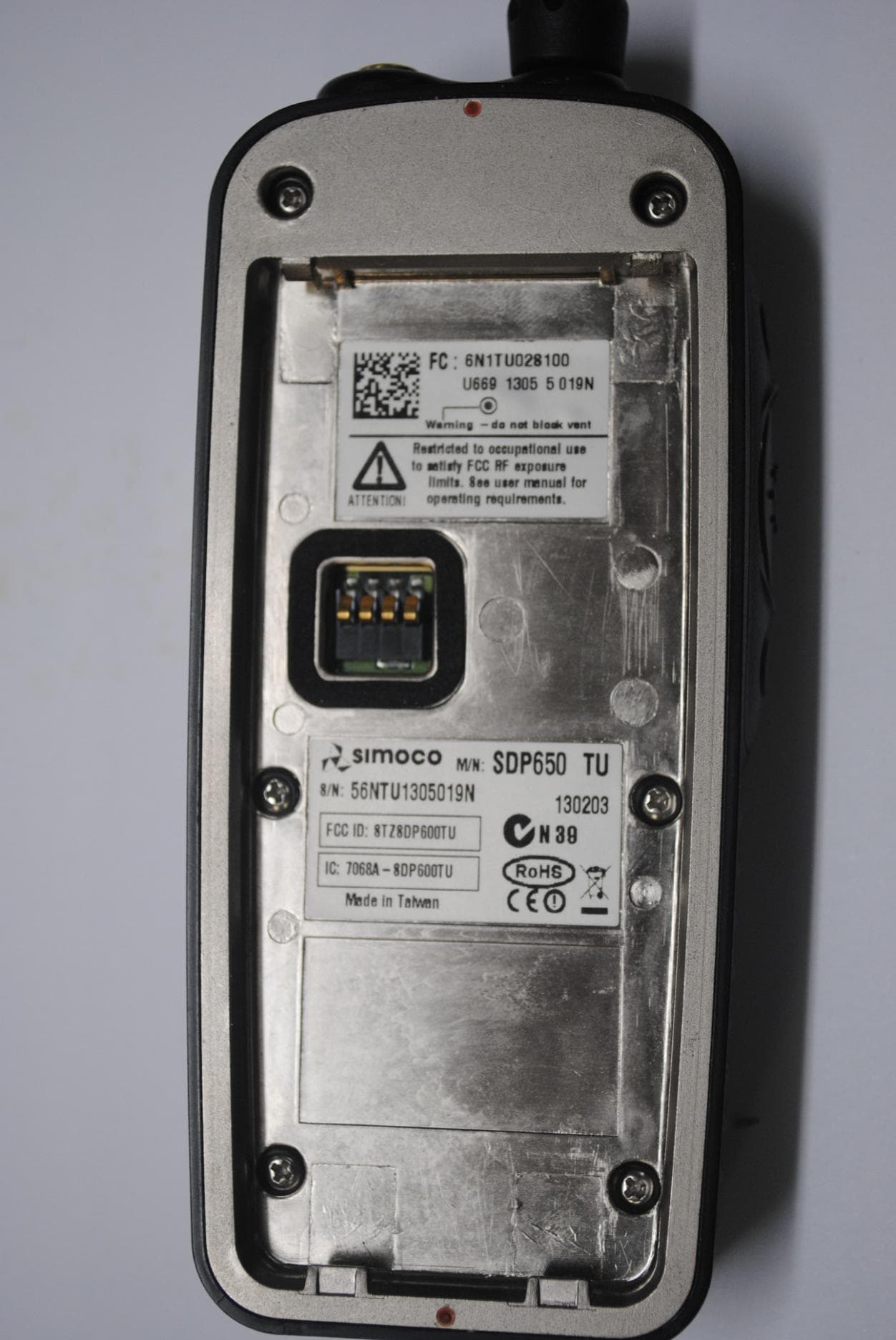
STZSDP600TU
Sep 10, 2013SDP600TU series UHF PMR/DMR Portable Transceiver
Equipment Class
TNF - Licensed Non-Broadcast Transmitter Held to Face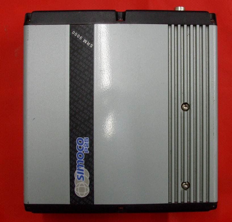
STZSRMA9000TU
Dec 13, 2012UHF MOBILE TRANSCEIVER
Equipment Class
TNB - Licensed Non-Broadcast Station Transmitter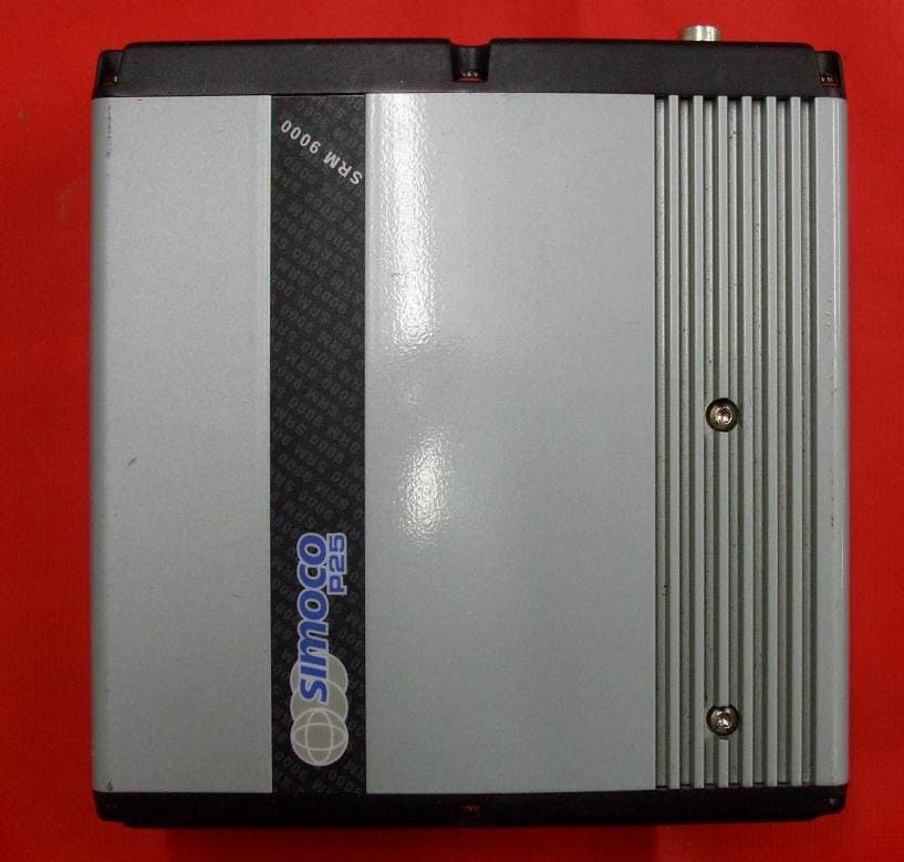
STZSRMA9000AC
Dec 12, 2012VHF MOBILE TRANSCEIVER
Equipment Class
TNB - Licensed Non-Broadcast Station Transmitter