T58DL4304RADSL2+ MODEM WITH 150MBPS WIRELESS-N ROUTER
NETIS SYSTEMS CO., LTD.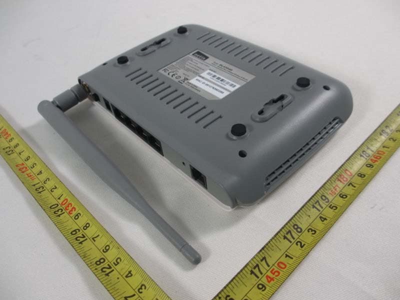
Click to zoom
Application Details
- Equipment Class
- DTS - Digital Transmission System
- Date of Grant
- Jan 13, 2013
- Application Purpose
- Original Equipment
- Date of Application
- Jan 13, 2013
- Equipment Note
- ADSL2+ MODEM WITH 150MBPS WIRELESS-N ROUTER
- Frequency Range
- 2422.00000000 - 2452.00000000
- Company
- NETIS SYSTEMS CO., LTD.
- Country
- China
Documents & Files
Document Text
Text extracted from the exhibit documents filed with the FCC. Open a document above to read the original.
Users Manual
DL4304D ADSL2+ Modem Plus 150Mbps Wireless-N Router Quick Installation Guide 1 1. Hardware Installation Step 1: Connect the ADSL Line. Method one: Plug one end of the twisted‐pair ADSL cable into the ADSL LINE port on the rear panel of the router, and insert the other end into the wall socket. Method two: You can use a separate splitter. The external splitter has three ports: • Line: Connect to the wall jack • Phone: Connect to the phone sets • Modem: Connect to the ADSL LINE port of the router Step 2: Connect the Ethernet cable. Attach one end of a network cable to your computer's Ethernet port or a regular hub/switch port, and the other end to the LAN port on the router. Step 3: Power on the computers and LAN devices. Step 4: Attach the power adapter. Connect the power adapter to the 2 power connector on the rear of the device and plug in the adapter to a wall outlet or power extension. Figure 1 3 Name Status Indication PWR On Power is on Off Power is off ADSL Flash The ADSL negotiation is in progress On The LINE port is linked up. Off The LINE port is linked down. Internet Flash Data is being transferred over the Internet. On A successful PPP connection has been built. Off There is no successful PPP connection or the Router works on Bridge mode. WLAN Flash There is wireless data being transmitted. On The wireless function is enabled but no data is being transmitted. Off The wireless function is disabled. LAN(1‐4) Flash Data is being transferred over the 1‐4 (LAN) port. On There is a successful connection on the corresponding 1‐4 (LAN) port but no activity. Off There is no connection on the corresponding 1‐4 (LAN) port or the connection is abnormal. 4 2. Configure PC ForWindows 7 or Windows Vista as below. Step 1: Click , then select the Open Network and Sharing Center. Figure 2 Step 2: Click the Change adapter settings. Figure 3 Step 3: Click Local Area Connection with the right button of your mouse. Then select Properties. 5 Figure 4 Step 4: Double click the “Internet Protocol Version 4(TCP/IPv4)”. Figure 5 6 Step 5: Select the “Obtain an IP address automatically” as below. Then click “OK”. Figure 6 3. Login Start your web browser and type the private IP address of the Router in the URL field: 192.168.1.1. Figure 7 Then,enter the default User Name admin and the default 7 Passwordadmin Figure 8 And then click OK to access to the Wireless Modem Management Panelscreen. 4. Modem Management This webpage provides you the convenient and simplest way to configure your Modem to access the internet. Firstly. Click and go to “Setup”‐>”WAN” , Page is showing below: (we are taking PPPoE for example) Secondly. Enter the VPI and VCI provided by your ISP and select the Channel mode as PPPoE Third: Enter the Fixed IP address which provided by your ISP then 8 click “ Add” Fourth: Click “Save” botton to make it effetive. Figure 9 5. Wireless Network&Security To connect to the Wireless AP, we should have the most basic configuration of the router at first. In this section, you can set the 9 wireless network parameters required to access the AP of your WLAN interface. Go to Setup->WLAN->Basic page, you can configure the wireless parameters. Here you may enable or disable the wireless function. You can also change the wireless parameters, such as Band, SSID, Channel Width, Control Sideband, Channel Number and Radio Power. Figure 10 Step 2:Go to Setup->WLAN->Security page, you can configure the wireless security parameters. 10 Here you can choose the encryption method to prevent any unauthorized access to your wireless network. There are three most commonly used encryption method (a total of six encryption support), including the WEP encryption, WPA-Personal, WPA2-Personal, etc. Click “Apply Changes” to make it effective Figure 11 Step 3: Click “My Network Places” with the right button of your mouse. Then select “Properties”. Step 4: C of your m Step 5: D Click “Wireless mouse. Then se Double click the 11 Figure 1 s Network Con elect “View Ava Figure 1 e wireless netw 2 nection” with ailable Wireless 3 ork your produ the right butto s Networks”. ct provided. on 12 Figure 14 Step 6: Input the key you stetted before if the wireless network you connecting to requests password. Certification FCC CE FCC Statement This equipment has been tested and found to comply with the limits for a Class B digital device, pursuant to part 15 of the FCC Rules. These limits are designed to pro‐vide reasonable protection against harmful interference in a residential installation. This equipment generates uses and can radiate radio frequency energy and, if not in‐stalled and used in accordance with the instructions, may cause 13 harmful interference to radio communications. However, there is no guarantee that interference will not occur in a particular installation. If this equipment does cause harmful interference to radio or television reception, which can be determined by turning the equipment off and on, the user is encouraged to try to correct the interference by one or more of the following measures: • Reorient or relocate the receiving antenna. • Increase the separation between the equipment and receiver. • Connect the equipment into an outlet on a circuit different from that to which the receiver is connected. • Consult the dealer or an experienced radio/ TV technician for help. This equipment complies with FCC RF radiation exposure limits set forth for an uncontrolledenvironment. This transmitter must not be co‐located or operating in conjunction with any otherantenna or transmitter. This equipment should be installed and operated with a minimumdistance of 20 centimeters between the radiator and your body. This unit complies with Part 15 & 68 of FCC Rules. Operation is subject to following two conditions: 1) This device may not cause harmful interference 2) This device must accept any interference received, including. Interference that may cause undesired operation. Any changes or modifications not expressly approved by…
Text truncated - open the document above for the full version.
Cover Letter(s)
CERTIFICATE OF COMPLIANCE Ref No.: NEI-FCCE-1-1105C155A Date of Issue: Dec. 26, 2012 Authorized under Declaration of Conformity according to 47 CFR, Part 2 and Part 15 of the FCC Rules. The product listed in follows was (were) tested in the Neutron EMC Laboratory to comply with the criteria limits Class B of conducted and radiated emissions of the Technical Standards FCC Part 15, Subpart B, established by the FCC, USA. Equipment ADSL2+ Modem Plus 150Mbps Wireless-N Router Model Name DL4304;DL4304D Brand Name netis Applicant NETIS SYSTEMS CO., LTD. Address 9F,B Block,Tsinghua Information Park, High-tech Industrial Park,Nanshan,Shenzhen,China Measurement ANSI C63.4 (2009) Method The test data, data evaluation, and equipment configuration contained in our test report (Ref No. NEI-FCCE-1-1105C155A) were obtained utilizing the test procedures, test instruments, test sites that has been accredited by the Authority of NVLAP and TAF according to the ISO-17025 quality assessment standard and technical standard(s). The test data contained in the referenced test report relate only to the EUT sample and item(s) tested. Andy Chiu Authorized Signatory Neutron Engineering Inc. B1, No.37, Lane 365, Yang Guang St., NeiHu District 114., Taipei, Taiwan TEL:+886-2-2657-3299 FAX:+886-2-2657-3331
External Photos
Neutron Engineering Inc. Project No.: 1105C155A Page 2 of 10 Model: DL-4304 Neutron Engineering Inc. Project No.: 1105C155A Page 3 of 10 Model: DL-4304D Neutron Engineering Inc. Project No.: 1105C155A Page 4 of 10 Neutron Engineering Inc. Project No.: 1105C155A Page 5 of 10 Neutron Engineering Inc. Project No.: 1105C155A Page 6 of 10
Internal Photos
Neutron Engineering Inc. Project No.: 1105C155A Page 7 of 10 Neutron Engineering Inc. Project No.: 1105C155A Page 8 of 10 Neutron Engineering Inc. Project No.: 1105C155A Page 9 of 10 Neutron Engineering Inc. Project No.: 1105C155A Page 10 of 10
Operational Description
1 規 格 承 認 書 Approval Sheet 客 戶 名 稱 Customer Name: NETIS 產 品 名 稱 Product description: RF Antenna assembly 產 品 型 號 Model Name: RG178 (R-SMA) 泓 淋 料 號 Hong Lin P/N: 戶號 客料 Customer P/N: 版 別 日 期 Version: X2 D ate: 2012-12-27 戶認簽 客承 印 CUSTOMER APPROVED BY 應認簽 供商承 印 VENDER APPROVED BY Checked By: Checked By:肖辉君 Approval By: Approval By:梁兴源 廠 工 /Factory: 1) 寶區崗鎮 圍 業區棟 深圳市 安 松 沙浦 村第二工 六 ; 電話 +86-755-27090678; 電 子信箱: [email protected] Building 6.No.2 Industrial Park, Shapuwei, Songgang To w n , Baoan District,Shenzhen, Guangdong, China; Te l : + 8 6‐755‐27090678 ; E‐mail:[email protected] 2) 蘇術產業園 江 省常熟市高新技 柳州路8 號 ; 電話 : +86-512-51538298; 電 子信箱: [email protected] No.8 Liuzhou Road, Yushan Industrial Park, Hi‐tech Development Zone, Changshu, Jiangsu, China Tel:+86-512-51538298; E-mail:[email protected] Building 6.No.2 Industrial Park, Shapuwei, Songgang To w n , Baoan District,Shenzhen, Guangdong, China; Tel:+86‐755‐27090678 ; E‐mail:[email protected] 2 履历表 版次号 修改章节 修改页码 生效日期 文件和资料更改申 请通知单 更改记录人 X2 修改封面 名称、规格 表、成品 图、 1、2、3、4 页 2012-12-27 肖辉君 3 一、Specification 1.1 Electrical Properties 1.1.1 Frequency Range‐‐‐‐‐‐‐‐‐‐‐‐‐‐‐‐‐‐‐‐2.4~2.5GHz 1.1.2 Impedance‐‐‐‐‐‐‐‐‐‐‐‐‐‐‐‐‐‐‐‐‐‐‐‐‐‐‐‐‐50Ω 1.1.3 VSWR‐‐‐‐‐‐‐‐‐‐‐‐‐‐‐‐‐‐‐‐‐‐‐‐‐‐‐‐‐‐‐‐‐‐‐‐1.92:1 1.1.4 Return Loss‐‐‐‐‐‐‐‐‐‐‐‐‐‐‐‐‐‐‐‐‐‐‐‐‐‐‐ ‐10dB or Less 1.1.5 Radiation ‐‐‐‐‐‐‐‐‐‐‐‐‐‐‐‐‐‐‐‐‐‐‐‐‐‐‐‐‐‐‐Ommi‐directional 1.1.6 Peak Gain‐‐‐‐‐‐‐‐‐‐‐‐‐‐‐‐‐‐‐‐‐‐‐‐‐‐‐‐‐‐‐ 5 .28dBi 1.1.7 Ad mitted Power‐‐‐‐‐‐‐‐‐‐‐‐‐‐‐‐‐‐‐‐‐‐‐ 1W 1.1.8 Polarization ‐‐‐‐‐‐‐‐‐‐‐‐‐‐‐‐‐‐‐‐‐‐‐‐‐‐‐‐Linear,Vertical 1.1.9 Cable‐‐‐‐‐‐‐‐‐‐‐‐‐‐‐‐‐‐‐‐‐‐‐‐‐‐‐‐‐‐‐‐‐‐‐‐‐ RG178 1.2 Physical Properties 1.2.1 An t enna Body‐‐‐‐‐‐‐‐‐‐‐‐‐‐‐‐‐‐‐‐‐‐‐‐‐PC 1.2.2 Antenna cover‐‐‐‐‐‐‐‐‐‐‐‐‐‐‐‐‐‐‐‐‐‐‐‐‐ TPE 1.2.3 Antenna Base‐‐‐‐‐‐‐‐‐‐‐‐‐‐‐‐‐‐‐‐‐‐‐‐‐‐PC 1.2.4 Operating Temp‐‐‐‐‐‐‐‐‐‐‐‐‐‐‐‐‐‐‐‐‐‐ ‐10°C~+60°C 1.2.5 Storage Temp‐‐‐‐‐‐‐‐‐‐‐‐‐‐‐‐‐‐‐‐‐‐‐‐‐ ‐10°C~+70°C 1.2.6 Color‐‐‐‐‐‐‐‐‐‐‐‐‐‐‐‐‐‐‐‐‐‐‐‐‐‐‐‐‐‐‐‐‐‐‐‐‐‐Gray 4 二、成品图 三.测试报告 VSWR 3D、2DRaditation Pattern: 2.4GHz Gain: 5.13dBi Efficiency:84.2% 2.45GHz Gain:5.01dBi Efficiency:83.6% 2.5GHz Gain:5.28dBi Efficiency:86.3% 4.9GHz Gain:5.01dBi Efficiency:84.7% 5.15GHz Gain:4.94dBi Efficiency:80.4% 5.35GHz Gain:4.97dBi Efficiency:82.8% 5.825GHz Gain:5.13dBi Efficiency:85.9% 四.CABLE规格 五.SGS报告 (注:SGS测试报告以电子档形式传给贵司)
RF Exposure Info
Neutron Engineering Inc. FCC RF EXPOSURE REPORT FCC ID: T58DL4304R Project No. : 1105C155A Equipment : ADSL2+ Modem Plus 150Mbps Wireless-N Router Model : DL4304;DL4304D Applicant : NETIS SYSTEMS CO., LTD Address : 9F,B Block,Tsinghua Information Park, High-tech Industrial Park, Nanshan, Shenzhen, China Manufacturer : Shenzhen Netcore Industrial Ltd. Address : 9F,B Block, Tsinghua Information Park, High-tech Industrial Park, Nanshan, Shenzhen, China According: : FCC Guidelines for Human Exposure IEEE C95.1 Testing Engineer : (David Mao) Technical Manager : (Leo Hung) Authorized Signatory : (Steven Lu) Neutron Engineering Inc. No.3, Jinshagang 1st Road, ShiXia, Dalang Town, Dong Guan, China. TEL : (0769) 8318-3000 FAX : (0769) 8319-6000 Neutron Engineering Inc. MPE CALCULATION METHOD: Calculation Method of RF Safety Distance: where: S = power density P = power input to the antenna G = power gain of the antenna in the direction of interest relative to an isotropic radiator R = distance to the center of radiation of the antenna ANT Brand name Model NameAntenna Type Connector Gain (dBi) 1 HONGLIN 2.4GHz 5dBi Dipole Antenna N/A 5.28 TEST RESULTS EUT: ADSL2+ Modem Plus 150Mbps Wireless-N Router Model Name : DL4304 Temperature: 24 °C Relative Humidity: 60 % Pressure: 1016 hPa Test Voltage : AC 120V/60Hz Test Mode : TX B MODE /CH01, CH06, CH11 Antenna Gain (dBi) Antenna Gain (numeric) Peak Output Power (dBm) Peak Output Power (mW) Power Density (S) (mW/cm 2 ) Limit of Power Density (S) (mW/cm 2 ) Te s t Result 5.28 3.3729 15.71 37.2392 0.025000601 Complies 5.28 3.3729 16.42 43.8531 0.029440851 Complies 5.28 3.3729 16.38 43.4510 0.029170941 Complies Neutron Engineering Inc. EUT: ADSL2+ Modem Plus 150Mbps Wireless-N Router Model Name : DL4304 Temperature: 24 °C Relative Humidity: 60 % Pressure: 1016 hPa Test Voltage : AC 120V/60Hz Test Mode : TX G MODE /CH01, CH06, CH11 Antenna Gain (dBi) Antenna Gain (numeric) Peak Output Power (dBm) Peak Output Power (mW) Power Density (S) (mW/cm 2 ) Limit of Power Density (S) (mW/cm 2 ) Te s t Result 5.28 3.3729 16.09 40.6443 0.027286661 Complies 5.28 3.3729 16.39 43.5512 0.029238181 Complies 5.28 3.3729 16.05 40.2717 0.027036491 Complies EUT: ADSL2+ Modem Plus 150Mbps Wireless-N Router Model Name : DL4304 Temperature: 24 °C Relative Humidity: 60 % Pressure: 1016 hPa Test Voltage : AC 120V/60Hz Test Mode : TX N-20M MODE /CH01, CH06, CH11 Antenna Gain (dBi) Antenna Gain (numeric) Peak Output Power (dBm) Peak Output Power (mW) Power Density (S) (mW/cm 2 ) Limit of Power Density (S) (mW/cm 2 ) Te s t Result 5.28 3.3729 17.46 55.7186 0.037406781 Complies 5.28 3.3729 17.58 57.2796 0.038454781 Complies 5.28 3.3729 16.94 49.4311 0.033185651 Complies EUT: ADSL2+ Modem Plus 150Mbps Wireless-N Router Model Name : DL4304 Temperature: 24 °C Relative Humidity: 60 % Pressure: 1016 hPa Test Voltage : AC 120V/60Hz Test Mode : TX N-40M MODE /CH03, CH06, CH09 Antenna Gain (dBi) Antenna Gain (numeric) Peak Output Power (dBm) Peak Output Power (mW) Power Density (S) (mW/cm 2 ) Limit of Power Density (S) (mW/cm 2 ) Te s t Result 5.28 3.3729 15.26 33.5738 0.022539821 Complies 5.28 3.3729 16.33 42.9536 0.028837021 Complies 5.28 3.3729 16.81 47.9733 0.032207011 Complies
Test Report
Neutron Engineering Inc. Report No.: NEI-FCCP-1-1105C155A Page 1 of 122 FCC Radio Test Report FCC ID: T58DL4304R This report concerns (check one) : Original Grant Class II Change Issued Date : Dec. 26, 2012 Project No. : 1105C155A Equipment : ADSL2+ Modem Plus 150Mbps Wireless-N Router Model Name : DL4304;DL4304D Applicant : NETIS SYSTEMS CO., LTD Address : 9F,B Block,Tsinghua Information Park, High-tech Industrial Park, Nanshan, Shenzhen, China Manufacturer : Shenzhen Netcore Industrial Ltd. Address : 9F,B Block, Tsinghua Information Park, High-tech Industrial Park, Nanshan, Shenzhen, China Tested by: Neutron Engineering Inc. EMC Laboratory Date of Receipt: Dec. 06, 2012 Date of Test: Dec. 06, 2012 ~ Dec. 25, 2012 Testing Engineer : (David Mao) Technical Manager : (Leo Hung) Authorized Signatory : (Steven Lu) Neutron Engineering Inc. No.3,Jinshagang 1st Road, ShiXia, Dalang Town, Dong Guan, China. TEL : (0769) 8318-3000 FAX : (0769) 8319-6000 Neutron Engineering Inc. Report No.: NEI-FCCP-1-1105C155A Page 2 of 122 Declaration Neutron represents to the client that testing is done in accordance with standard procedures as applicable and that test instruments used has been calibrated with the standards traceable to National Measurement Laboratory (NML) of R.O.C, or National Institute of Standards and Technology (NIST) of U.S.A. Neutron's reports apply only to the specific samples tested under conditions. It is manufacture’s responsibility to ensure that additional production units of this model are manufactured with the identical electrical and mechanical components. Neutron shall have no liability for any declarations, inferences o r generalizations drawn by the client or others from Neutron issued reports. Neutron’s reports must not be used by the client to claim product endorsement by the authorities or any agency of the Government. This report is the confidential property of the client. As a mutual protection to the clients, the public and Neutron-self, extracts from the test report shall not be reproduced except in full with Neutron’s authorized written approval. Neutron’s laboratory quality assurance procedures are in compliance with the ISO Guide 17025 requirements, and accredited by the conformity assessment authorities listed in this test report. Limitation For the use of the authority's logo is limited unless the Test Standard(s)/Scope(s)/Item(s) mentioned in this test report is (are) included in the conformity assessment authorities acceptance respective. Neutron Engineering Inc. Report No.: NEI-FCCP-1-1105C155A Page 3 of 122 Table of Contents Page 1 . CERTIFICATION 5 2 . SUMMARY OF TEST RESULTS 6 2.1 TEST FACILITY 7 2.2 MEASUREMENT UNCERTAINTY 7 3 . GENERAL INFORMATION 8 3.1 GENERAL DESCRIPTION OF EUT 8 3.2 DESCRIPTION OF TEST MODES 10 3.3 TABLE OF PARAMETERS OF TEXT SOFTWARE SETTING 11 3.4 BLOCK DIAGRAM SHOWING THE CONFIGURATION OF SYSTEM TESTED 12 3.5 DESCRIPTION OF SUPPORT UNITS 14 4 . EMC EMISSION TEST 15 4.1 CONDUCTED EMISSION MEASUREMENT 15 4.1.1 POWER LINE CONDUCTED EMISSION LIMITS 15 4.1.2 MEASUREMENT INSTRUMENTS LIST AND SETTING 15 4.1.3 TEST PROCEDURE 16 4.1.4 DEVIATION FROM TEST STANDARD 16 4.1.5 TEST SETUP 16 4.1.6 EUT OPERATING CONDITIONS 16 4.1.7 TEST RESULTS 17 4.2 RADIATED EMISSION MEASUREMENT 20 4.2.1 RADIATED EMISSION LIMITS 20 4.2.2 MEASUREMENT INSTRUMENTS LIST ANS SETTING 21 4.2.3 TEST PROCEDURE 22 4.2.4 DEVIATION FROM TEST STANDARD 22 4.2.5 TEST SETUP 23 4.2.6 EUT OPERATING CONDITIONS 24 4.2.7 TEST RESULTS (BETWEEN 30 – 1000 MHZ) 26 4.2.8 TEST RESULTS (ABOVE 1000 MHZ) 29 5 . BANDWIDTH TEST 77 5.1 APPLIED PROCEDURES / LIMIT 77 5.1.1 MEASUREMENT INSTRUMENTS LIST 77 5.1.2 TEST PROCEDURE 77 5.1.3 DEVIATION FROM STANDARD 77 5.1.4 TEST SETUP 77 5.1.5 EUT OPERATION CONDITIONS 77 5.1.6 TEST RESULTS 78 6 . MAXIMUM OUTPUT POWER TEST 86 Neutron Engineering Inc. Report No.: NEI-FCCP-1-1105C155A Page 4 of 122 Table of Contents Page 6.1 APPLIED PROCEDURES / LIMIT 86 6.1.1 MEASUREMENT INSTRUMENTS LIST 86 6.1.2 TEST PROCEDURE 86 6.1.3 DEVIATION FROM STANDARD 86 6.1.4 TEST SETUP 86 6.1.5 EUT OPERATION CONDITIONS 86 6.1.6 TEST RESULTS 87 7 . ANTENNA CONDUCTED SPURIOUS EMISSION 89 7.1 APPLIED PROCEDURES / LIMIT 89 7.1.1 MEASUREMENT INSTRUMENTS LIST 89 7.1.2 TEST PROCEDURE 89 7.1.3 DEVIATION FROM STANDARD 89 7.1.4 TEST SETUP 89 7.1.5 EUT OPERATION CONDITIONS 89 7.1.6 TEST RESULTS 90 8 . POWER SPECTRAL DENSITY TEST 110 8.1 APPLIED PROCEDURES / LIMIT 110 8.1.1 MEASUREMENT INSTRUMENTS LIST 110 8.1.2 TEST PROCEDURE 110 8.1.3 DEVIATION FROM STANDARD 110 8.1.4 TEST SETUP 110 8.1.5 EUT OPERATION CONDITIONS 110 8.1.6 TEST RESULTS 111 9 . EUT TEST PHOTO 119 Neutron Engineering Inc. Report No.: NEI-FCCP-1-1105C155A Page 5 of 122 1. CERTIFICATION Equipment : ADSL2+ Modem Plus 150Mbps Wireless-N Router Brand Name : netis Model Name : DL4304;DL4304D Applicant : NETIS SYSTEMS CO., LTD Factory : Dongguan City Netcore Network Technology Co.,Ltd. Address : No.10-1,Sankeng Road,Qinghutou,Tangxia Town,Dongguan City Date of Test : Dec. 06, 2012 ~ Dec. 25, 2012 Test Item : ENGINEERING SAMPLE Standards : FCC Part15, Subpart C(15.247) / ANSI C63.4 2003 The above equipment has been tested and found compliance with the requirement of the relative standards by Neutron Engineering Inc. EMC Laboratory. The test data, data evaluation, and equipment configuration contained in our test report (Ref No. NEI-FCCP-1-1105C155A) were obtained utilizing the test procedures, test instruments, test sites that has been accredited by the Authority of NVLAP and TAF according to the ISO-17025 quality assessment standard and technical standard(s). . Neutron Engineering Inc. Report No.: NEI-FCCP-1-1105C155A Page 6 of 122 2. SUMMARY OF TEST RESULTS Test procedures according to the technical standards: FCC Part15 (15.247) , Subpart C Standard Section Test Item Judgment Remark 15.207 Conducted Emission PASS 15.247(d) Antenna conducted Spurious EmissionPASS 15.247(a)(2) 6dB Bandwidth PASS 15.247(b)(3) Peak Output Power PASS 15…
Text truncated - open the document above for the full version.
Test Setup Photos
Neutron Engineering Inc. Report No.: NEI-FCCP-1-1105C155A Page 118 of 120 9. EUT TEST PHOTO Conducted Measurement Photos Neutron Engineering Inc. Report No.: NEI-FCCP-1-1105C155A Page 119 of 120 Radiated Measurement Photos Neutron Engineering Inc. Report No.: NEI-FCCP-1-1105C155A Page 120 of 120 Radiated Measurement Photos
Contact Information
Applicant
Kinki Wang(Auditor)
Test Firm
BTL Inc.Daisy Dai
Technical Specifications
| # | Rule Parts | Frequency Range | Power Output |
|---|---|---|---|
| 2 | 15C | 2.42 GHz - 2.45 GHz | 48.00 mW |
Other Applications from NETIS SYSTEMS CO., LTD.
T58NX30R
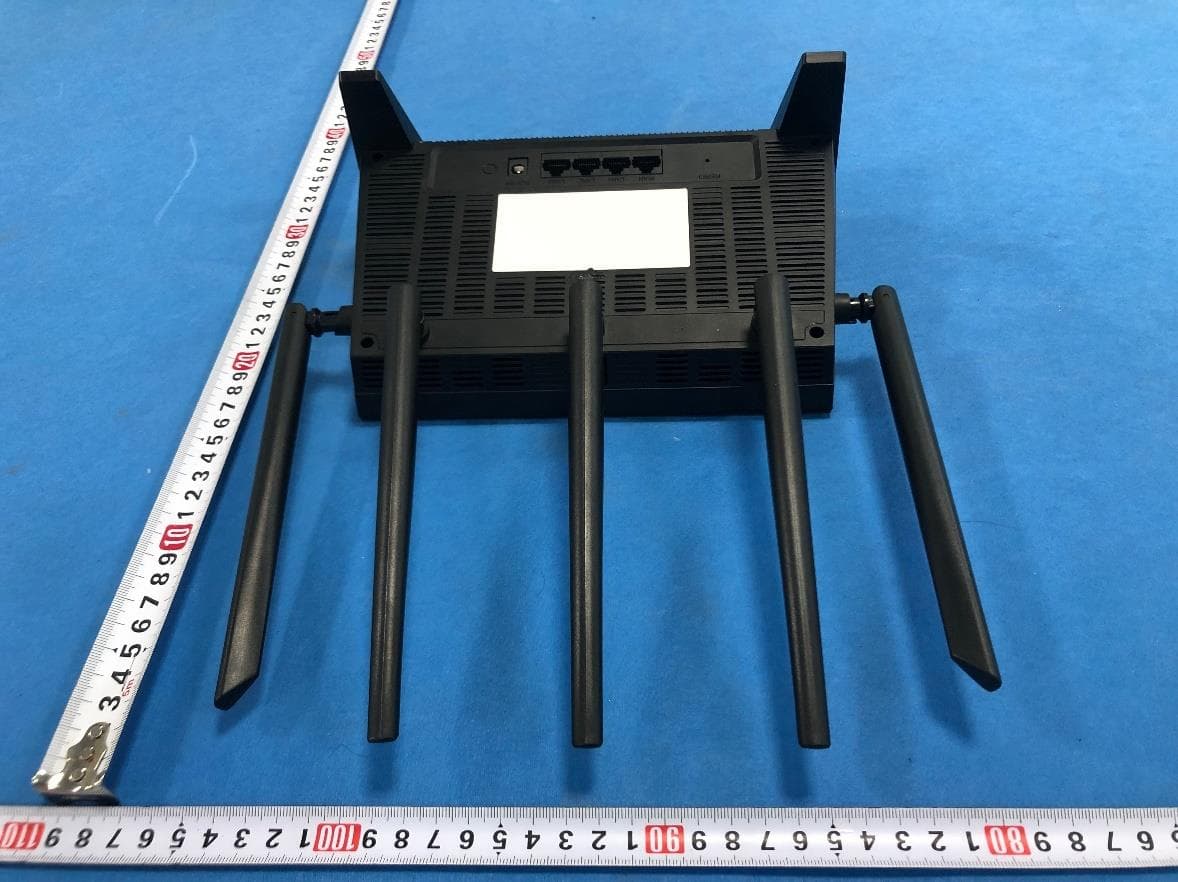
Apr 20, 2023AX3000 Wireless Dual-Band WiFi6 Router
Equipment Class
DTS - Digital Transmission System
T58M6R
Jul 03, 2022AX1800 Whole Home Mesh WiFi 6 System
Equipment Class
NII - Unlicensed National Information Infrastructure TX
T58N6TR
Jun 05, 2022AX1800 Dual-Band Wireless Router
Equipment Class
DTS - Digital Transmission System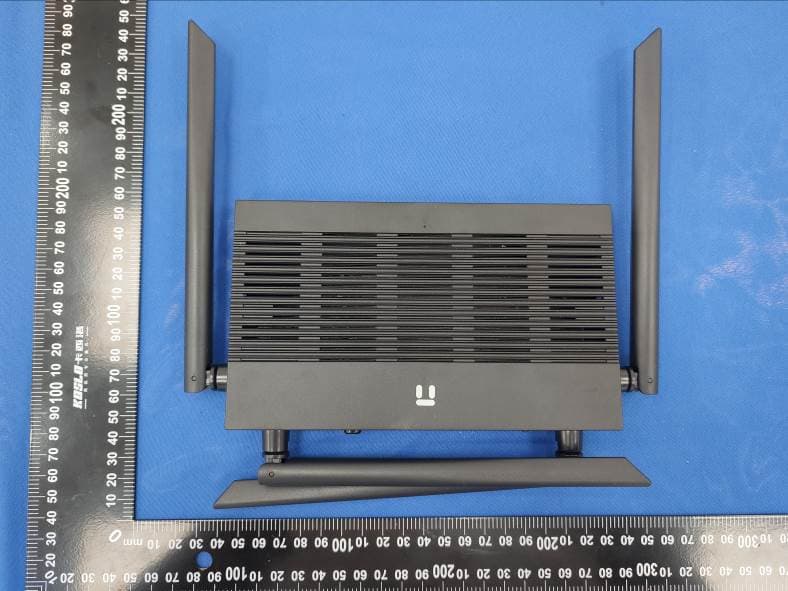
T58N3R
Sep 26, 2021AC1200 Wireless Dual Band Gigabit Router
Equipment Class
NII - Unlicensed National Information Infrastructure TX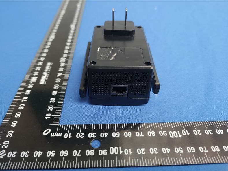
T58E3R
Jul 17, 2021AC1200 Dual Band WiFi Repeater
Equipment Class
DTS - Digital Transmission System