T58DL4310R150Mbps Wireless N ADSL2+ Modem Router
NETIS SYSTEMS CO., LTD.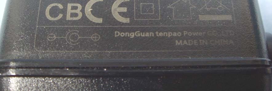
Click to zoom
Application Details
- Equipment Class
- DTS - Digital Transmission System
- Date of Grant
- May 08, 2014
- Application Purpose
- Original Equipment
- Date of Application
- May 08, 2014
- Equipment Note
- 150Mbps Wireless N ADSL2+ Modem Router
- Frequency Range
- 2422.00000000 - 2452.00000000
- Company
- NETIS SYSTEMS CO., LTD.
- Country
- China
Documents & Files
Document Text
Text extracted from the exhibit documents filed with the FCC. Open a document above to read the original.
Users Manual
netis Wireless N ADSL2+ Modem Router Quick Installation Guide R CONTENTS 1 English 6 Español 11 Português 16 Français 1.Package Contents * This QIG is for all netis 150Mbps/300Mbps wireless N ADSL2+ modem routers, including models- DL4310, DL4310D, DL4311, DL4311D, DL4312, DL4312D, DL4322, DL4322D, DL4323, DL4323D , etc. * The product model shown in this QIG is DL4323, as an example. netis Wireless N ADSL2+ Modem Router Quick Installation Guide 1 2.Hardware Connection Wireless N ADSL2+ Modem Router Power Adapter ADSL Splitter Ethernet CableTelephone Cable *2 QIG MODEM netis Wireless N ADSL2+ Modem Router Quick Installation Guide 2.1. Connect the ADSL line with the attached telephone cable. Connect the LINE port of ADSL Splitter to the wall jack with a telephone cable. Connect the MODEM port of ADSL Splitter to the ADSL port on netis Modem Router with the other telephone cable. Connect your telephone to the PHONE port of ADSL Splitter. Tip: If no telephone is needed, please connect the ADSL port on netis Modem Router to the wall jack with the phone cable directly. 2.2. Connect your computer to one of the LAN ports on netis Modem Router with an Ethernet cable. 2.3. Plug the provided Power Adapter into the PWR jack of netis Modem Router and the other end to a standard electrical socket. 2.4. Wait for one minute then check if the LED indicators of the Modem Router display normally. PWR: Solid on. ADSL: Solid on when the modem is synchronized. LAN: Solid on or flashing if the corresponding LAN port is connected. Tip: If the LED indicators display abnormally, please check if all the cables are well connected. If the ADSL LED is off or flashing, please contact your ISP (Internet Service Provider) to check the Internet connection. PHONE 2 3. Configure the Modem Router via Web Management Page 3.1. Necessary Information before the configuration. For a successful setup, you're recommended to contact your ISP first and ask for the following network parameters which will be required during the configuration procedures. a. VPI/VCI; b. Connection Type; c. Encapsulation Type (Optional); d. Username & Password (Optional, according to your Connection Type). 3.2. Set the IP address of the wired network adapter on your computer as “Automatic” or “DHCP”. For Windows 8/ 7/Vista 1) Go to “Settings” (Win 8)/“Start” (Win 7/Vista)> “Control Panel”. 2) Left-click on “Network and Internet”> “Network and Sharing Center”> “Change adapter settings” (Win 8/7)/“Manage network connections” (Win Vista). 3) Right-click on “Local Area Connection” and left-click on “Properties”. 4) Double-click on “Internet Protocol Version 4 (TCP/IPv4)”. 5) Select “Obtain an IP address automatically” and “Obtain DNS server address automatically” then left-click on “OK”. For Windows XP/2000 1) Go to “Start”> “Control Panel”. 2) Left-click on “Network and Internet Connections”> “Network Connections”. 3) Right-click on “Local Area Connection” and left-click on “Properties”. 4) Double-click on “Internet Protocol (TCP/IP)”. 5) Select “Obtain an IP address automatically” and “Obtain DNS server address automatically” then left-click on “OK”. For MAC OS 1) Click on the “Apple” menu> “System Preferences”. 2) Click on the “Network” icon. 3) Click on “Ethernet” in the left side box and click on “Advanced” in the lower right corner. 4) In the top options, select “TCP/IP”. 5) In the pull-down menu next to “Configure IPv4” select “Using DHCP”. 6) Click “OK” then “Apply”. 192.168.1.1 3.3. Open your browser and type 192.168.1.1 in the address field. Then type in the username guest and password guest to login the web management page. netis Wireless N ADSL2+ Modem Router Quick Installation Guide 3 3.4. Under “Quick Start” page, left-click on “START” and the Wizard will guide you through the following four steps. Then left-click on “NEXT”. 1) Set the PVC (VPI/VCI) value. Left-click “Cancel” if you know the PVC (VPI/VCI) from your ISP, then input the value manually. If you don't know the exact value, please left-click on “OK”, and then it will take less than one minute to search for the available PVC automatically. Once the PVC value is input or shows up in the following page, left-click on “NEXT”. netis Wireless N ADSL2+ Modem Router Quick Installation Guide 3) Configure your wireless network name (SSID) and password, and then left-click on “NEXT”. 4) Left-click on “NEXT” and then “CLOSE” to save the current settings. Quick Start will be finished. 2) Select the Internet Connection Type given by your ISP, then left-click on “NEXT”. If “Dynamic IP Address” is selected, select the Connection Type defined by your ISP and the router will automatically receive the IP parameters from your ISP. If “Static IP Address” is selected, enter the IP Address/Subnet Mask/ISP Gateway/DNS Servers/Connection Type given by your ISP. If “PPPoE/PPPoA” is selected, input the Username/ Password and select the Connection Type given by your ISP. If “Bridge Mode” is selected, select the Connection Type defined by your ISP. Tip 1: Default IP address: 192.168.1.1 Default login username: guest Default SSID: netis Default login password: guest Default wireless password: password 4 netis Wireless N ADSL2+ Modem Router Quick Installation Guide Tip 2: After the basic Internet settings, you may open some popular websites to check your Internet connection. If you cannot access the Internet, please refer to the instructions in “Troubleshooting”. How do I restore my netis Modem Router's configuration to its default settings? With the router powered on, use a pin to press and hold the Default button on the rear panel for 8 to 10 seconds before releasing it. The router will reboot and all configurations are back to factory default. Q A 4.Troubleshooting What can I do if my Internet cannot be accessed? 1) Check to verify the hardware connections are correct. Please refer to the “Hardware Connection” step. 2) Login to netis Modem Router's web management page and ensure that you input the correct netwo…
Text truncated - open the document above for the full version.
Attestation Statements
NETIS SYSTEMS CO., LTD 4F & 5F, R&D Building, Oriental Cyberport, High-Tech Industrial Park, Nanshan, Shenzhen, China Date (February ,26 ,2014) Federal Communications Commission 7435 Oakland Mills Road Columbia MD 21046 c.c. Compliance Certification Services Certification Division 47173 Benicia Street Fremont, CA 94538, USA Dear Sir or Madam, Due to the business consideration, we hereby declare that our product of 150Mbps Wireless N ADSL2+ Modem Router Model: DL4310; DL4310D have as following difference Serial model DL4310 with fixed antenna; DL4310D with detachable antenna Any questions regarding this declaration, please don’t hesitate to contact us. Sincerely, Signature___________________________________ Name/Title: SelenaBai / Director Contact information / Address 4F & 5F, R&D Building, Oriental Cyberport, High-Tech Industrial Park, Nanshan, Shenzhen, China TEL: +86 0755-86186790 FAX: +86 0755-86186779 Email: [email protected]
Cover Letter(s)
NETIS SYSTEMS CO., LTD 4F & 5F, R&D Building, Oriental Cyberport, High-Tech Industrial Park, Nanshan, Shenzhen, China Date :February 26 ,2014 Federal Communications Commission Authorization and Evaluation Division 1435 Oakland Mills Road Columbia, MD 21046 SUBJECT: FCC Application for FCC ID: T58DL4310R To Whom It May Concern: We, as the grantee of this project FCC ID: T58DL4310R, would like to declare that the composite portion categorized as computer peripheral h as been authorized under the Declaration of Conformity procedures. Sincerely yours, Name/Title: SelenaBai / Director Contact information / Address 4F & 5F, R&D Building, Oriental Cyberport, High-Tech Industrial Park, Nanshan, Shenzhen, China TEL: +86 0755-86186790 FAX: +86 0755-86186779 Email: [email protected]
Cover Letter(s)
NETIS SYSTEMS CO., LTD 4F & 5F, R&D Building, Oriental Cyberport, High-Tech Industrial Park, Nanshan, Shenzhen, China Federal Communications Commission 7435 Oakland Mills Road Columbia MD 21046 Date: April,08 ,2014 Subject: Request for Confidentiality FCC ID: T58DL4310R To Whom It May Concern: Pursuant to the provisions of Sections 0.457 and 0.459 of the Commission’s rules (47 CFR §§ 0.457, 0.459), we are requesting the Commission to withhold the following attachments as confidential document from public disclosure indefinitely. Schematic Diagram Block Diagram Theory of Operation ANT specification Above mentioned document contains detailed system and equipment description are considered as proprietary information in operation of the equipment. The public disclosure of above documents might be harmful to our company and would give competitor an unfair advantage in the market. In additional to above mentioned documents, pursuant to Public Notice DA 04-1705 of the Commission’s policy, in order to comply with the marketing regulations in 47 CFR §2.803 and the importation rules in 47 CFR §2.1204, while ensuring that business sensitive information remains confidential until the actual marketing of newly authorized devices. We are requesting the commission to grant short-term confidentiality request on the following attachments until 2014/05/30. External Photos Internal Photos User Manual It is our understanding that all measurement test reports, FCC ID label format and correspondent during certification review process cannot be granted as confidential documents and those information will be available for public review once the grant of equipment authorization is issued. Best Regards Sincerely yours, ___________________________ Name/Title: SelenaBai / Director April,08 ,2014
Cover Letter(s)
Letter of Authorization We Name: NETIS SYSTEMS CO., LTD. Address: 4F&5F R&D Building,Oriental Cyberport High-Tech Industrial Park, Nanshan, Shenzhen, China Declare the following Person: Name: Alex Chen Title:Vice President is authorized to sign all the related doucuments of FCC certification,the signature has the same effectas as SelenaBai: on our behalf. Authorized Person: SelenaBai Signature: City: Shenzhen Date: 2014-2-26
External Photos
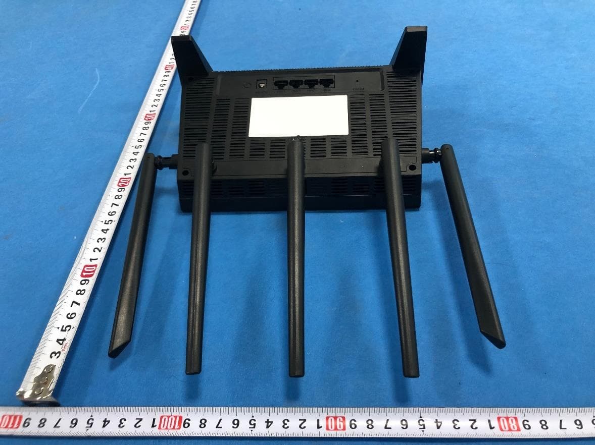
Report No: T140310D04 Page 4 Rev.00 DL4310D Report No: T140310D04 Page 5 Rev.00 Report No: T140310D04 Page 6 Rev.00 Report No: T140310D04 Page 7 Rev.00 Antenna Report No: T140310D04 Page 8 Rev.00 Tenpao / NT120050UL
External Photos
Report No: T140310D04 Page 1 / 16 Rev.00 EXTERNAL PHOTOGRAPHS OF EUT DL4310 Report No: T140310D04 Page 2 Rev.00 Report No: T140310D04 Page 3 Rev.00
ID Label/Location Info
DL4310 MADE IN CHINA Default Settings: IP Address: 192.168.1.1 User Name: guest Password: guest SSID: netis Wireless Password: password Input:12V 500mA REN:0.1B US:SX5DL01BDL4310R FCC ID:T58DL4310R MAC Address:
Internal Photos
Report No: T140310D04 Page 12 Rev.00 DL4310D Report No: T140310D04 Page 13 Rev.00 Report No: T140310D04 Page 14 Rev.00 Report No: T140310D04 Page 15 Rev.00 Report No: T140310D04 Page 16 Rev.00
Internal Photos
Report No: T140310D04 Page 9 Rev.00 INTERNAL PHOTOGRAPHS OF EUT DL4310 Report No: T140310D04 Page 10 Rev.00 Report No: T140310D04 Page 11 Rev.00
RF Exposure Info
Compliance Certification Services Inc. Report No.: T140310D04-MF Date of Issue: March 28, 2014 Page 1 Rev.00 This report shall not be reproduced except in full, without the written approval of Compliance Certification Services. APPENDIX I RADIO FREQUENCY EXPOSURE LIMIT According to §15.247(i), systems operating under the provisions of this section shall be operated in a manner that ensures that the public is not exposed to radio frequency energy levels in excess of the Commission's guidelines. See § 1.1307(b)(1) of this chapter. EUT Specification EUT 150Mbps Wireless N ADSL2+ Modem Router Model DL4310; DL4310D RF Module Realtek Model: RTL8188ER-CG Model Discrepancy All the model numbers (list on this report) are identical, just for marketing purpose only except Antenna. Model Number Antenna DL4310 Fixed DL4310D Detachable Frequency band (Operating) 802.11b/g/n HT20: 2.412GHz ~ 2.462GHz 802.11n HT40: 2.422GHz ~ 2.452GHz Others Device category Portable (<20cm separation) Mobile (>20cm separation) Others Exposure classification Occupational/Controlled exposure (S = 5mW/cm 2 ) General Population/Uncontrolled exposure (S=1mW/cm 2 ) Antenna Specification 2.4GHz: Antenna Gain :5.00 dBi (Numeric gain:3.16) Maximum Average output power IEEE 802.11b Mode: 12.96 dBm(19.770 mW) IEEE 802.11g Mode: 15.23 dBm(33.343 mW) IEEE 802.11n HT 20 Mode: 15.22 dBm(33.266 mW) IEEE 802.11n HT 40 Mode: 17.43 dBm(55.335 mW) Maximum Tune up Power IEEE 802.11b Mode: 14.00 dBm(25.119 mW) IEEE 802.11g Mode: 16.00 dBm(39.811 mW) IEEE 802.11n HT 20 Mode: 16.00 dBm(39.811 mW) IEEE 802.11n HT 40 Mode: 18.00 dBm(63.096 mW) Evaluation applied MPE Evaluation* SAR Evaluation N/A Compliance Certification Services Inc. Report No.: T140310D04-MF Date of Issue: March 28, 2014 Page 2 Rev.00 This report shall not be reproduced except in full, without the written approval of Compliance Certification Services. Revision History Rev. Issue Date Revisions Effect Page Revised By 00 2014/03/28 Initial Issue ALL Scott Hsu Compliance Certification Services Inc. Report No.: T140310D04-MF Date of Issue: March 28, 2014 Page 3 Rev.00 This report shall not be reproduced except in full, without the written approval of Compliance Certification Services. TEST RESULTS No non-compliance noted. Calculation Given d GP E 30 & 377 2 E S Where E = Field strength in Volts / meter P = Power in Watts G = Numeric antenna gain d = Distance in meters S = Power density in milliwatts / square centimeter Combining equations and re-arranging the terms to express the distance as a function of the remaining variables yields: 2 377 30 d GP S Changing to units of mW and cm, using: P (mW) = P (W) / 1000 and d (cm) = d(m) / 100 Yields 22 0796.0 100/377 1000/30 d GP d GP S Equation 1 Where d = Distance in cm P = Power in mW G = Numeric antenna gain S = Power density in mW / cm 2 Compliance Certification Services Inc. Report No.: T140310D04-MF Date of Issue: March 28, 2014 Page 4 Rev.00 This report shall not be reproduced except in full, without the written approval of Compliance Certification Services. Maximum Permissible Exposure Substituting the MPE safe distance using d = 20 cm into Equation 1: GPS000199.0 Where P = Power in mW G = Numeric antenna gain S = Power density in mW / cm 2 IEEE 802.11b mode: Ch.Frq.(MHz)P (mW)Gain (num.)D (cm) Power density in mW / cm 2 Limit (mW/cm2) 6243725.1193.16200.01581 IEEE 802.11g mode: Ch.Frq.(MHz)P (mW)Gain (num.)D (cm) Power density in mW / cm 2 Limit (mW/cm2) 6243739.8113.16200.02501 IEEE 802.11n HT20 mode: Ch.Frq.(MHz)P (mW)Gain (num.)D (cm) Power density in mW / cm 2 Limit (mW/cm2) 6243739.8113.16200.02501 IEEE 802.11n HT40 mode: Ch.Frq.(MHz)P (mW)Gain (num.)D (cm) Power density in mW / cm 2 Limit (mW/cm2) 6243763.0963.16200.03971
Test Setup Photos
Compliance Certification Services Inc. Report No.: T140310D04-RP1 FCC ID: T58DL4310R Date of Issue: March 20, 2014 Page 83 Rev.00 8 APPENDIX I PHOTOGRAPHS OF TEST SETUP Radiated Emissions Setup Photos Below 1GHz Compliance Certification Services Inc. Report No.: T140310D04-RP1 FCC ID: T58DL4310R Date of Issue: March 20, 2014 Page 84 Rev.00 Above 1GHz Compliance Certification Services Inc. Report No.: T140310D04-RP1 FCC ID: T58DL4310R Date of Issue: March 20, 2014 Page 85 Rev.00 Conducted Emissions Setup Photo Compliance Certification Services Inc. Report No.: T140310D04-RP1 FCC ID: T58DL4310R Date of Issue: March 20, 2014 Page 86 Rev.00 Powerline Conducted Emissions Setup Photos
Contact Information
Applicant
Kinki Wang(Auditor)
Test Firm
Compliance Certification Services Inc.Kurt Chen
Technical Specifications
| # | Rule Parts | Frequency Range | Power Output |
|---|---|---|---|
| 2 | 15C | 2.42 GHz - 2.45 GHz | 263.00 mW |
Other Applications from NETIS SYSTEMS CO., LTD.
T58NX30R
Apr 20, 2023AX3000 Wireless Dual-Band WiFi6 Router
Equipment Class
DTS - Digital Transmission System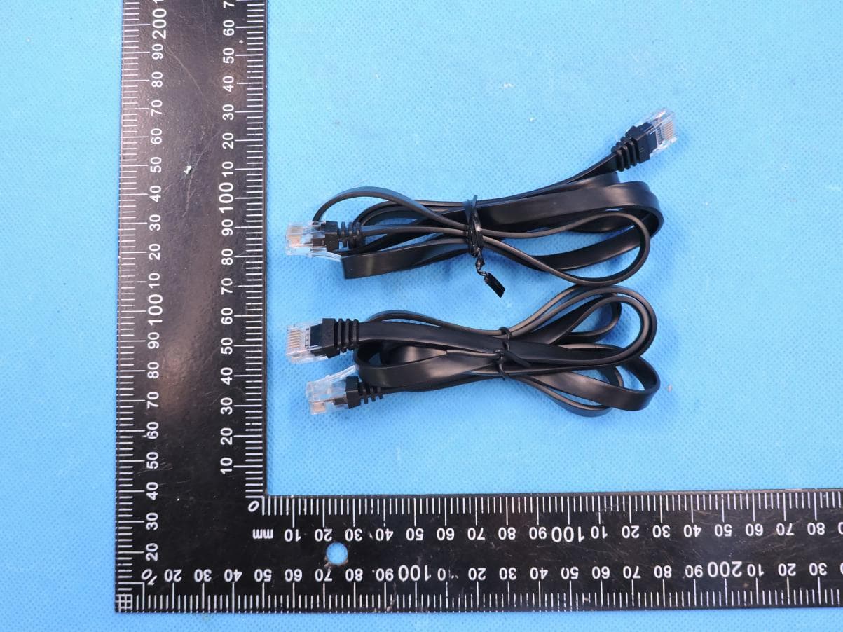
T58M6R
Jul 03, 2022AX1800 Whole Home Mesh WiFi 6 System
Equipment Class
NII - Unlicensed National Information Infrastructure TX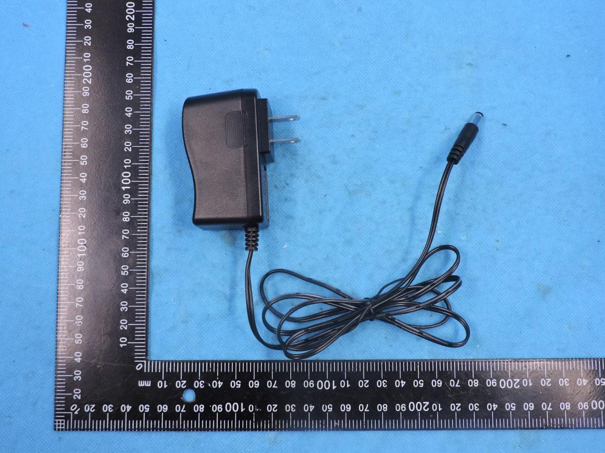
T58N6TR
Jun 05, 2022AX1800 Dual-Band Wireless Router
Equipment Class
DTS - Digital Transmission System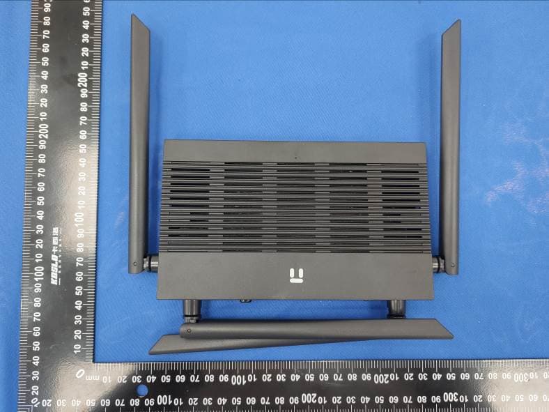
T58N3R
Sep 26, 2021AC1200 Wireless Dual Band Gigabit Router
Equipment Class
NII - Unlicensed National Information Infrastructure TX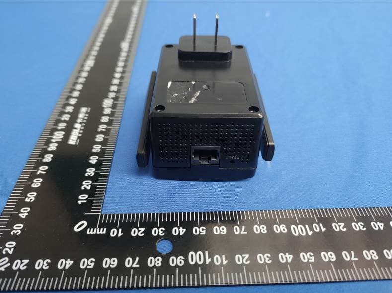
T58E3R
Jul 17, 2021AC1200 Dual Band WiFi Repeater
Equipment Class
DTS - Digital Transmission System