T58WF2520R300Mbps Wireless N High Power Ceiling-Mounted Access Point
NETIS SYSTEMS CO., LTD.
Click to zoom
Application Details
- Equipment Class
- DTS - Digital Transmission System
- Date of Grant
- Apr 23, 2015
- Application Purpose
- Original Equipment
- Date of Application
- Apr 23, 2015
- Equipment Note
- 300Mbps Wireless N High Power Ceiling-Mounted Access Point
- Frequency Range
- 2422.00000000 - 2452.00000000
- Company
- NETIS SYSTEMS CO., LTD.
- Country
- China
Documents & Files
Document Text
Text extracted from the exhibit documents filed with the FCC. Open a document above to read the original.
Users Manual
netis Wireless High Power Ceiling/Wall Mounted Outdoor AP Router Quick Installation Guide R Model No. WF2520P WF2520 1.Package Contents Please make sure that the package contains above items, if any of the listed items are damaged or missing, please contact your distributor. Ceiling/wall Mounted AP Router netis Wireless High Power Outdoor AP Router Quick Installation Guide netis Wireless High Power Ceiling/Wall mounted AP Router Quick Installation Guide 1 2.Hardware Connection The following items should be found in your package: PoE Injector for WF2520P only Power Adapter Quick Installation Guide Ceiling Mounting Kit Wall mounting Kit (for WF2520P only) * This QIG is for all netis Wireless High Power AP Router, including modelsCeiling/Wall mounted as below WF2520P: This device supports both Passive PoE and regular Power adapter(DC24V/0.5A). You may use either one as power source. WF2520:This device only supports IEEE802.3af/at PoE. * Top Cover of Product * LED Indicator * I/O of Bottom Cover LED SYSTEM WLAN Color Red Blue Mode Solid Red Off Fast Blinking Slow Blinking Solid Blue Blinking Status Power ON and system is booting After system boot finished When firmware is upgrading WiFi disabled After system boot finished and no wireless date is being transmitted There is wireless date being transmitted There is no ''DC-IN' on WF2520 2 2) WF2520P(Power source:DC-IN) A) Connect the power adapter to DC-IN port of the device and plug the other end to wall outlet; B) Connect the Ethernet cable into WAN/PoE port of the device and the other end to the Ethernet port of PC. Computer WF2520P netis Wireless High Power Ceiling/Wall mounted AP Router Quick Installation Guide LAN/WAN LAN/WAN 1)WF2520P (Power source:PoE) A) Connect one end of the Ethernet cable into the WAN/PoE port of the device and the other end to the PoE port of the PoE injector. B) Connect the Power Adapter to DC-in port of the PoE injector and plug the other end to wall outlet. C) Connect the Ethernet cable into LAN/WAN port of PoE injector and the other end to the Ethernet port of the PC. PC 3 3) WF2520 (Power source:PoE switch) A) Connect one end of the Ethernet cable into the WAN/PoE port of the device and the other end to the Ethernet port of PoE switch. B) Connect one end of the Ethernet cable into an Ethernet port of the PoE switch and the other end to the Ethernet port of PC. netis Wireless High Power Ceiling/Wall mounted AP Router Quick Installation Guide WF2520 PoE switch 3. Configure the AP Router via Web Management Page This device works in AP mode by default, so if you are intend to change the working mode or any settings, please connect your computer to WAN/PoE or LAN Port of AP and set a static IP for you computer as below steps: 3.1 Set a Static IP for PC Manually set the IP address of the wired network adapter on your computer as below. IP Address/ IPv4 Address: 192.168.1.x (1<x<255) Subnet Mask: 255.255.255.0 Default Gateway/ Router: 192.168.1.1 For Windows 8/ 7/Vista 1) Go to “Settings” (for Windows 8)/“Start” (for Windows 7/Vista) > “Control Panel”. 2) Left-click on “Network and Internet” > “Network and Sharing Center” > “Change adapter settings” (for Windows 8/ 7)/”Manage network connections” (for Windows Vista). 3) Right-click on “Local Area Connection” and left-click on “Properties”. 4) Double-click on “Internet Protocol Version 4 (TCP/IPv4)”. 5) Select “Use the following IP address” then left-click on “OK”. For Windows XP/2000 1) Go to “Start” > “Control Panel”. 2) Left-click on “Network and Internet Connections” > “Network Connections”. 3) Right-click on “Local Area Connection” and left-click on “Properties”. 4) Double-click on “Internet Protocol (TCP/IP)”. 5) Select “Use the following IP address” then left-click on “OK”. For MAC OS 1) Click on the “Apple” menu > “System Preferences”. 2) Click on the “Network” icon. 3) Click on “Ethernet” in the left side box and click on “Advanced” in the lower right corner. 4) In the top options, select “TCP/IP”. 5) In the pull-down menu next to “Configure IPv4” select “Manually”. 6) Fill in the “IPv4 Address/Subnet Mask/Router” parameters, and click “OK” then “Apply”. netis Wireless High Power Ceiling/Wall mounted AP Router Quick Installation Guide 4 3.3 A dialog box will prompt as below, please enter User Name and Password, both default values are guest and click OK. Note: The configuration includes “Internet Connection” and “Wireless Setup”, if you choose “AP”, please go to Wireless Setup. AP Router Mode: Select the correct Connection Type. PPPoESelect “PPPoE” when: 1. The device is connected to a DSL or Cable pure modem. 2. Got username &password from ISP . 3. Broadband connection is needed on PC when bypassing This device. Type in the Username & Password provided by the ISP. DHCP Select “DHCP” when: 1. The device is connected to a Cable/DSL modem router. 2. Internet works directly on PC when bypassing this Device. (Dynamic IP) Static IPSelect “Static IP ” when: 1. Got IP Address, Subnet Mask, Default Gateway, DNS Server from ISP. Type in all the IP Info. 3.2 Open your browser and type http://192.168.1.1 in the address field to visit router's web management page. 5 netis Wireless High Power Ceiling/Wall mounted AP Router Quick Installation Guide WISP Mode : Select target network and Connection Type. 1. Click “AP Scan” button to select your target network and click “Connect” button. 2. Type in the wireless security info of the target network. 3. Select connection type. (Please refer to “Internet Settings” →“AP Router Mode”) Note: The DHCP Server will be disabled after switching to “AP” mode successfully, so you will have to set a static IP address for your PC first if you need to login to the web-based management page again. 3.4 The web management page will display after login successfully. Select the language as you need on the top box, default is in English. Wireless Setup Setup a wireless network name in “SSID” box, it is recommended to use WPA-PSK/WPA2-PSK for “Secur…
Text truncated - open the document above for the full version.
Users Manual
netis Wireless High Power Ceiling/Wall Mounted Outdoor AP Router Quick Installation Guide R Model No. WF2520P WF2520 1.Package Contents Please make sure that the package contains above items, if any of the listed items are damaged or missing, please contact your distributor. Ceiling/wall Mounted AP Router netis Wireless High Power Outdoor AP Router Quick Installation Guide netis Wireless High Power Ceiling/Wall mounted AP Router Quick Installation Guide 1 2.Hardware Connection The following items should be found in your package: PoE Injector for WF2520P only Power Adapter Quick Installation Guide Ceiling Mounting Kit Wall mounting Kit (for WF2520P only) * This QIG is for all netis Wireless High Power AP Router, including modelsCeiling/Wall mounted as below WF2520P: This device supports both Passive PoE and regular Power adapter(DC24V/0.5A). You may use either one as power source. WF2520:This device only supports IEEE802.3af/at PoE. * Top Cover of Product * LED Indicator * I/O of Bottom Cover LED SYSTEM WLAN Color Red Blue Mode Solid Red Off Fast Blinking Slow Blinking Solid Blue Blinking Status Power ON and system is booting After system boot finished When firmware is upgrading WiFi disabled After system boot finished and no wireless date is being transmitted There is wireless date being transmitted There is no ''DC-IN' on WF2520 2 2) WF2520P(Power source:DC-IN) A) Connect the power adapter to DC-IN port of the device and plug the other end to wall outlet; B) Connect the Ethernet cable into WAN/PoE port of the device and the other end to the Ethernet port of PC. Computer WF2520P netis Wireless High Power Ceiling/Wall mounted AP Router Quick Installation Guide LAN/WAN LAN/WAN 1)WF2520P (Power source:PoE) A) Connect one end of the Ethernet cable into the WAN/PoE port of the device and the other end to the PoE port of the PoE injector. B) Connect the Power Adapter to DC-in port of the PoE injector and plug the other end to wall outlet. C) Connect the Ethernet cable into LAN/WAN port of PoE injector and the other end to the Ethernet port of the PC. PC 3 3) WF2520 (Power source:PoE switch) A) Connect one end of the Ethernet cable into the WAN/PoE port of the device and the other end to the Ethernet port of PoE switch. B) Connect one end of the Ethernet cable into an Ethernet port of the PoE switch and the other end to the Ethernet port of PC. netis Wireless High Power Ceiling/Wall mounted AP Router Quick Installation Guide WF2520 PoE switch 3. Configure the AP Router via Web Management Page This device works in AP mode by default, so if you are intend to change the working mode or any settings, please connect your computer to WAN/PoE or LAN Port of AP and set a static IP for you computer as below steps: 3.1 Set a Static IP for PC Manually set the IP address of the wired network adapter on your computer as below. IP Address/ IPv4 Address: 192.168.1.x (1<x<255) Subnet Mask: 255.255.255.0 Default Gateway/ Router: 192.168.1.1 For Windows 8/ 7/Vista 1) Go to “Settings” (for Windows 8)/“Start” (for Windows 7/Vista) > “Control Panel”. 2) Left-click on “Network and Internet” > “Network and Sharing Center” > “Change adapter settings” (for Windows 8/ 7)/”Manage network connections” (for Windows Vista). 3) Right-click on “Local Area Connection” and left-click on “Properties”. 4) Double-click on “Internet Protocol Version 4 (TCP/IPv4)”. 5) Select “Use the following IP address” then left-click on “OK”. For Windows XP/2000 1) Go to “Start” > “Control Panel”. 2) Left-click on “Network and Internet Connections” > “Network Connections”. 3) Right-click on “Local Area Connection” and left-click on “Properties”. 4) Double-click on “Internet Protocol (TCP/IP)”. 5) Select “Use the following IP address” then left-click on “OK”. For MAC OS 1) Click on the “Apple” menu > “System Preferences”. 2) Click on the “Network” icon. 3) Click on “Ethernet” in the left side box and click on “Advanced” in the lower right corner. 4) In the top options, select “TCP/IP”. 5) In the pull-down menu next to “Configure IPv4” select “Manually”. 6) Fill in the “IPv4 Address/Subnet Mask/Router” parameters, and click “OK” then “Apply”. netis Wireless High Power Ceiling/Wall mounted AP Router Quick Installation Guide 4 3.3 A dialog box will prompt as below, please enter User Name and Password, both default values are guest and click OK. Note: The configuration includes “Internet Connection” and “Wireless Setup”, if you choose “AP”, please go to Wireless Setup. AP Router Mode: Select the correct Connection Type. PPPoESelect “PPPoE” when: 1. The device is connected to a DSL or Cable pure modem. 2. Got username &password from ISP . 3. Broadband connection is needed on PC when bypassing This device. Type in the Username & Password provided by the ISP. DHCP Select “DHCP” when: 1. The device is connected to a Cable/DSL modem router. 2. Internet works directly on PC when bypassing this Device. (Dynamic IP) Static IPSelect “Static IP ” when: 1. Got IP Address, Subnet Mask, Default Gateway, DNS Server from ISP. Type in all the IP Info. 3.2 Open your browser and type http://192.168.1.1 in the address field to visit router's web management page. 5 netis Wireless High Power Ceiling/Wall mounted AP Router Quick Installation Guide WISP Mode : Select target network and Connection Type. 1. Click “AP Scan” button to select your target network and click “Connect” button. 2. Type in the wireless security info of the target network. 3. Select connection type. (Please refer to “Internet Settings” →“AP Router Mode”) Note: The DHCP Server will be disabled after switching to “AP” mode successfully, so you will have to set a static IP address for your PC first if you need to login to the web-based management page again. 3.4 The web management page will display after login successfully. Select the language as you need on the top box, default is in English. Wireless Setup Setup a wireless network name in “SSID” box, it is recommended to use WPA-PSK/WPA2-PSK for “Secur…
Text truncated - open the document above for the full version.
Cover Letter(s)
NETIS SYSTEMS CO., LTD 4F & 5F, R&D Building, Oriental Cyberport, High-Tech Industrial Park, Nanshan, Shenzhen, China Date : March , 11 ,2015 BABT FCB Forsyth House, Churchfield Road, Walton-on-Thames, Surrey, KT12 2TD Dear Sir or Madam, We, NETIS SYSTEMS CO., LTD hereby authorize Compliance Certification Services Inc / David.Wang toact as our agent in all matters relating to applications for equipment authorization, including thesigning of all documents relating to these matters. This authorization expires on 10/01/2015 Sincerely, _____________________________________ Signature Name/Title: SelenaBai / Director Contact information / Address 4F & 5F, R&D Building, Oriental Cyberport, High-Tech Industrial Park, Nanshan, Shenzhen, China TEL: +86 0755-86186790 FAX: +86 0755-86186779 Email: [email protected]
Cover Letter(s)
Letter of Authorization We Name: NETIS SYSTEMS CO., LTD. Address: 4F&5F R&D Building,Oriental Cyberport High-Tech Industrial Park, Nanshan, Shenzhen, China Declare the following Person: Name: Alex Chen Title:Vice President is authorized to sign all the related doucuments of FCC certification,the signature has the same effectas as SelenaBai: on our behalf. Authorized Person: SelenaBai Signature: City: Shenzhen Date: 2014-2-26
Cover Letter(s)
NETIS SYSTEMS CO., LTD 4F & 5F, R&D Building, Oriental Cyberport, High-Tech Industrial Park, Nanshan, Shenzhen, China Date : March , 11 ,2015 BABT FCB Forsyth House, Churchfield Road, Walton-on-Thames, Surrey, KT12 2TD Dear Sir or Madam, We, NETIS SYSTEMS CO., LTD hereby authorize Compliance Certification Services Inc / David.Wang toact as our agent in all matters relating to applications for equipment authorization, including thesigning of all documents relating to these matters. This authorization expires on 10/01/2015 Sincerely, _____________________________________ Signature Name/Title: SelenaBai / Director Contact information / Address 4F & 5F, R&D Building, Oriental Cyberport, High-Tech Industrial Park, Nanshan, Shenzhen, China TEL: +86 0755-86186790 FAX: +86 0755-86186779 Email: [email protected]
Cover Letter(s)
NETIS SYSTEMS CO., LTD 4F & 5F, R&D Building, Oriental Cyberport, High-Tech Industrial Park, Nanshan, Shenzhen, China Date : March , 11 ,2015 BABT TCB Forsyth House, Churchfield Road, Walton-on-Thames, Surrey, KT12 2TD Confidentiality Request FCC ID: T58WF2520R Pursuant to Sections 0.457(d)(1)(ii) and 0.459 of the Commission’s Rules, NETIS SYSTEMS CO., LTD hereby requests permanent confidential treatment of information accompanying this application as outlined below: Common exhibits for which confidentiality is requested are: Schematics Block Diagrams Theory of Operation NETIS SYSTEMS CO., LTD also hereby requests short-term confidential treatment of information accompanying this application as outlined below for a period of 180 days Internal Photos External Photos User Manual Test Set-up Photographs The above materials contain trade secrets and proprietary information not customarily released to the public. The public disclosure of these matters might be harmful to the Applicant and provide unjustified benefits to its competitors. The Applicant understands that pursuant to Rule 0.457(d)(1)(ii), disclosure of this Application and all accompanying materials will not be made before the date of the Grant for this Application. Your Sincerely, _____________________________________ Signature Name/Title: SelenaBai / Director Contact information / Address 4F & 5F, R&D Building, Oriental Cyberport, High-Tech Industrial Park, Nanshan, Shenzhen, China TEL: +86 0755-86186790 FAX: +86 0755-86186779 Email: [email protected]
Cover Letter(s)
NETIS SYSTEMS CO., LTD 4F & 5F, R&D Building, Oriental Cyberport, High-Tech Industrial Park, Nanshan, Shenzhen, China Date : March , 11 ,2015 Federal Communications Commission Authorization and Evaluation Division 1435 Oakland Mills Road Columbia, MD 21046 SUBJECT: FCC Application for FCC ID: T58WF2520R To Whom It May Concern: We, as the grantee of this project FCC ID: T58WF2520R, would like to declare that the composite portion categorized as computer peripheral has been authorized under the Declaration of Conformity procedures. Sincerely yours, Name/Title: SelenaBai / Director Contact information / Address 4F & 5F, R&D Building, Oriental Cyberport, High-Tech Industrial Park, Nanshan, Shenzhen, China TEL: +86 0755-86186790 FAX: +86 0755-86186779 Email: [email protected]
External Photos
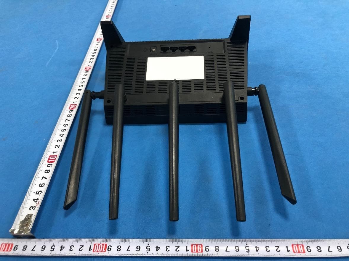
Report No.T150128D05 Page 1 of 6 External Photo (Model:WF2520) Report No.T150128D05 Page 2 of 6 I/OPort Report No.T150128D05 Page 3 of 6 External Photo (Model:WF2520P) Report No.T150128D05 Page 4 of 6 I/OPort Report No.T150128D05 Page 5 of 6 Power Adapter (For WF2520P) Report No.T150128D05 Page 6 of 6 POE (For WF2520P)
ID Label/Location Info
LLabel Loocationn
Internal Photos
Report No.T150128D05 Page 1 of 16 Internal Photo (Model:WF2520) Report No.T150128D05 Page 2 of 16 Report No.T150128D05 Page 3 of 16 Report No.T150128D05 Page 4 of 16 Report No.T150128D05 Page 5 of 16 Report No.T150128D05 Page 6 of 16 Report No.T150128D05 Page 7 of 16 Report No.T150128D05 Page 8 of 16 Internal Photo (Model:WF2520P) Report No.T150128D05 Page 9 of 16 Report No.T150128D05 Page 10 of 16 Report No.T150128D05 Page 11 of 16 Report No.T150128D05 Page 12 of 16 Report No.T150128D05 Page 13 of 16 Report No.T150128D05 Page 14 of 16 Report No.T150128D05 Page 15 of 16 Antenna (WF2520) Report No.T150128D05 Page 16 of 16 Antenna (WF2520P)
Internal Photos
Report No.T150128D05 Page 1 of 16 Internal Photo (Model:WF2520) Report No.T150128D05 Page 2 of 16 Report No.T150128D05 Page 3 of 16 Report No.T150128D05 Page 4 of 16 Report No.T150128D05 Page 5 of 16 Report No.T150128D05 Page 6 of 16 Report No.T150128D05 Page 7 of 16 Report No.T150128D05 Page 8 of 16 Internal Photo (Model:WF2520P) Report No.T150128D05 Page 9 of 16 Report No.T150128D05 Page 10 of 16 Report No.T150128D05 Page 11 of 16 Report No.T150128D05 Page 12 of 16 Report No.T150128D05 Page 13 of 16 Report No.T150128D05 Page 14 of 16 Report No.T150128D05 Page 15 of 16 Antenna (WF2520) Report No.T150128D05 Page 16 of 16 Antenna (WF2520P)
RF Exposure Info
Compliance Certification Services Inc. Report No.: T150128D05-RP1-1 Date of Issue: April 17, 2015 Page 1 Rev.00 This report shall not be reproduced except in full, without the written approval of Compliance Certification Services. RADIO FREQUENCY EXPOSURE LIMIT According to §15.247(i), systems operating under the provisions of this section shall be operated in a manner that ensures that the public is not exposed to radio frequency energy levels in excess of the Commission's guidelines. See § 1.1307(b)(1) of this chapter. EUT Specification EUT 300Mbps Wireless N High Power Ceiling-Mounted Access Point Model WF2520 Data Applies To WF2520P Frequency band (Operating) 802.11b/g/n HT20: 2.412GHz ~ 2.462GHz 802.11n HT40: 2.422GHz ~ 2.452GHz Others Device category Portable (<20cm separation) Mobile (>20cm separation) Others Exposure classification Occupational/Controlled exposure (S = 5mW/cm 2 ) General Population/Uncontrolled exposure (S=1mW/cm 2 ) Antenna Specification 2.4GHz: Antenna A Gain : 4.00 dBi (Numeric gain 2.51) 2.4GHz: Antenna B Gain : 3.80 dBi (Numeric gain 2.40) Maximum Average output power IEEE 802.11b Mode: 17.03 dBm (50.466 mW) IEEE 802.11g Mode: 21.72 dBm (148.594 mW) IEEE 802.11 gn HT 20 Mode: 27.33 dBm (540.754 mW) IEEE 802.11 gn HT 40 Mode: 26.60 dBm (457.088 mW) Evaluation applied MPE Evaluation* SAR Evaluation N/A Compliance Certification Services Inc. Report No.: T150128D05-RP1-1 Date of Issue: April 17, 2015 Page 2 Rev.00 This report shall not be reproduced except in full, without the written approval of Compliance Certification Services. Revision History Rev. Issue Date Revisions Effect Page Revised By 00 04/17/2015 Initial Issue ALL Gloria Chang Compliance Certification Services Inc. Report No.: T150128D05-RP1-1 Date of Issue: April 17, 2015 Page 3 Rev.00 This report shall not be reproduced except in full, without the written approval of Compliance Certification Services. TEST RESULTS No non-compliance noted. Calculation Given d GP E ×× = 30 & 3770 2 E S= Where E = Field strength in Volts / meter P = Power in Watts G = Numeric antenna gain d = Distance in meters S = Power density in milliwatts / square centimeter Combining equations and re-arranging the terms to express the distance as a function of the remaining variables yields: 2 3770 30 d GP S ×× = Changing to units of mW and cm, using: P (mW) = P (W) / 1000 and d (cm) = d(m) / 100 Yields () () 22 0796.0 100/3770 1000/30 d GP d GP S × ×= × ×× = Equation 1 Where d = Distance in cm P = Power in mW G = Numeric antenna gain S = Power density in mW / cm 2 Compliance Certification Services Inc. Report No.: T150128D05-RP1-1 Date of Issue: April 17, 2015 Page 4 Rev.00 This report shall not be reproduced except in full, without the written approval of Compliance Certification Services. Maximum Permissible Exposure Substituting the MPE safe distance using d = 20 cm into Equation 1: GPS××=000199.0 Where P = Power in mW G = Numeric antenna gain S = Power density in mW / cm 2 IEEE 802.11b mode: Frq.(MHz)P (mW) Gain (num.)D (cm) Power densit y in mW / cm 2 Limit (mW/cm 2 ) 2412~2462 50.4662.51200.02521 IEEE 802.11g mode: Frq.(MHz)P (mW) Gain (num.)D (cm) Power densit y in mW / cm 2 Limit (mW/cm 2 ) 2412~2462 148.5942.51200.07421 IEEE 802.11gn HT20 mode: Frq.(MHz)P (mW) Gain (num.)D (cm) Power densit y in mW / cm 2 Limit (mW/cm 2 ) 2412~2462 540.7542.51200.27011 IEEE 802.11gn HT40 mode: Frq.(MHz)P (mW) Gain (num.)D (cm) Power densit y in mW / cm 2 Limit (mW/cm 2 ) 2422~2452 457.0882.51200.22831
RF Exposure Info
Compliance Certification Services Inc. Report No.: T150128D05-RP1-1 Date of Issue: April 17, 2015 Page 1 Rev.00 This report shall not be reproduced except in full, without the written approval of Compliance Certification Services. RADIO FREQUENCY EXPOSURE LIMIT According to §15.247(i), systems operating under the provisions of this section shall be operated in a manner that ensures that the public is not exposed to radio frequency energy levels in excess of the Commission's guidelines. See § 1.1307(b)(1) of this chapter. EUT Specification EUT 300Mbps Wireless N High Power Ceiling-Mounted Access Point Model WF2520 Data Applies To WF2520P Frequency band (Operating) 802.11b/g/n HT20: 2.412GHz ~ 2.462GHz 802.11n HT40: 2.422GHz ~ 2.452GHz Others Device category Portable (<20cm separation) Mobile (>20cm separation) Others Exposure classification Occupational/Controlled exposure (S = 5mW/cm 2 ) General Population/Uncontrolled exposure (S=1mW/cm 2 ) Antenna Specification 2.4GHz: Antenna A Gain : 4.00 dBi (Numeric gain 2.51) 2.4GHz: Antenna B Gain : 3.80 dBi (Numeric gain 2.40) Maximum Average output power IEEE 802.11b Mode: 17.03 dBm (50.466 mW) IEEE 802.11g Mode: 21.72 dBm (148.594 mW) IEEE 802.11 gn HT 20 Mode: 27.33 dBm (540.754 mW) IEEE 802.11 gn HT 40 Mode: 26.60 dBm (457.088 mW) Evaluation applied MPE Evaluation* SAR Evaluation N/A Compliance Certification Services Inc. Report No.: T150128D05-RP1-1 Date of Issue: April 17, 2015 Page 2 Rev.00 This report shall not be reproduced except in full, without the written approval of Compliance Certification Services. Revision History Rev. Issue Date Revisions Effect Page Revised By 00 04/17/2015 Initial Issue ALL Gloria Chang Compliance Certification Services Inc. Report No.: T150128D05-RP1-1 Date of Issue: April 17, 2015 Page 3 Rev.00 This report shall not be reproduced except in full, without the written approval of Compliance Certification Services. TEST RESULTS No non-compliance noted. Calculation Given d GP E ×× = 30 & 3770 2 E S= Where E = Field strength in Volts / meter P = Power in Watts G = Numeric antenna gain d = Distance in meters S = Power density in milliwatts / square centimeter Combining equations and re-arranging the terms to express the distance as a function of the remaining variables yields: 2 3770 30 d GP S ×× = Changing to units of mW and cm, using: P (mW) = P (W) / 1000 and d (cm) = d(m) / 100 Yields () () 22 0796.0 100/3770 1000/30 d GP d GP S × ×= × ×× = Equation 1 Where d = Distance in cm P = Power in mW G = Numeric antenna gain S = Power density in mW / cm 2 Compliance Certification Services Inc. Report No.: T150128D05-RP1-1 Date of Issue: April 17, 2015 Page 4 Rev.00 This report shall not be reproduced except in full, without the written approval of Compliance Certification Services. Maximum Permissible Exposure Substituting the MPE safe distance using d = 20 cm into Equation 1: GPS××=000199.0 Where P = Power in mW G = Numeric antenna gain S = Power density in mW / cm 2 IEEE 802.11b mode: Frq.(MHz)P (mW) Gain (num.)D (cm) Power densit y in mW / cm 2 Limit (mW/cm 2 ) 2412~2462 50.4662.51200.02521 IEEE 802.11g mode: Frq.(MHz)P (mW) Gain (num.)D (cm) Power densit y in mW / cm 2 Limit (mW/cm 2 ) 2412~2462 148.5942.51200.07421 IEEE 802.11gn HT20 mode: Frq.(MHz)P (mW) Gain (num.)D (cm) Power densit y in mW / cm 2 Limit (mW/cm 2 ) 2412~2462 540.7542.51200.27011 IEEE 802.11gn HT40 mode: Frq.(MHz)P (mW) Gain (num.)D (cm) Power densit y in mW / cm 2 Limit (mW/cm 2 ) 2422~2452 457.0882.51200.22831
Test Report
FCC ID : T58WF2520R Report No.T150128D05-RP1 Page 1 / 106 This report shall not be reproduced, except in full, without the written approval of Compliance Certification Services Inc. FCC 47 CFR PART 15 SUBPART C AND ANSI C63.10:2009 TEST REPORT For 300Mbps Wireless N High Power Ceiling-Mounted Access Point Model : WF2520 Data Applies To : WF2520P Trade Name : netis Issued for NETIS SYSTEMS CO., LTD 4F & 5F, R&D Building, Oriental Cyberport, High-Tech Industrial Park, Nanshan, Shenzhen, China Issued by Compliance Certification Services Inc. Hsinchu Lab. No.989-1, Wenshan Rd., Shangshan Village, Qionglin Township, Hsinchu County 30741, Taiwan (R.O.C.) TEL: +886-3-5921698 FAX: +886-3-5921108 http://www.ccsrf.com E-Mail : [email protected] Issued Date: April 17, 2015 Note: This report shall not be reproduced except in full, without the written approval of Compliance Certification Services Inc. This document may be altered or revised by Compliance Certification Services Inc. personnel only, and shall be noted in the revision section of the document. The client should not use it to claim product endorsement by TAF or any government agencies. The test results of this report relate only to the tested sample identified in this report. FCC ID : T58WF2520R Report No.T150128D05-RP1 Page 2 / 106 This report shall not be reproduced, except in full, without the written approval of Compliance Certification Services Inc. Revision History Rev. Issue Date Revisions Effect Page Revised By 00 04/17/2015 Initial Issue All Page 106 Dola Hsieh FCC ID : T58WF2520R Report No.T150128D05-RP1 Page 3 / 106 This report shall not be reproduced, except in full, without the written approval of Compliance Certification Services Inc. TABLE OF CONTENTS TITLE PAGE NO. 1. TEST REPORT CERTIFICATION ................................................................................ 4 2. EUT DESCRIPTION ..................................................................................................... 5 3. DESCRIPTION OF TEST MODES ............................................................................... 7 4. TEST METHODOLOGY ............................................................................................... 9 5. FACILITIES AND ACCREDITATION ........................................................................... 9 5.1 FACILITIES ............................................................................................................ 9 5.2 ACCREDITATIONS................................................................................................ 9 5.3 MEASUREMENT UNCERTAINTY ......................................................................... 10 6. SETUP OF EQUIPMENT UNDER TEST...................................................................... 11 7. FCC PART 15.247 REQUIREMENTS.......................................................................... 12 7.1 6dB BANDWIDTH.................................................................................................. 12 7.2 MAXIMUM PEAK OUTPUT POWER ..................................................................... 26 7.3 AVERAGE POWER ............................................................................................... 29 7.4 POWER SPECTRAL DENSITY ............................................................................. 32 7.5 CONDUCTED SPURIOUS EMISSION .................................................................. 47 7.6 RADIATED EMISSION........................................................................................... 66 7.7 CONDUCTED EMISSION ...................................................................................... 99 APPENDIX SETUP PHOTOS .......................................................................................... 104 FCC ID : T58WF2520R Report No.T150128D05-RP1 Page 4 / 106 This report shall not be reproduced, except in full, without the written approval of Compliance Certification Services Inc. 1. TEST REPORT CERTIFICATION Applicant NETIS SYSTEMS CO., LTD Address 4F & 5F, R&D Building, Oriental Cyberport, High-Tech Industrial Park, Nanshan, Shenzhen, China Equipment Under Test 300Mbps Wireless N High Power Ceiling-Mounted Access Point Model WF2520 Data Applies To WF2520P Trade Name netis Tested Date January 28 ~ April 07, 2015 APPLICABLE STANDARD Standard Test Result FCC Part 15 Subpart C AND ANSI C63.10:2009 PASS WE HEREBY CERTIFY THAT: The above equipment has been tested by Compliance Certification Services Inc., and found compliance with the requirements set forth in the technical standards mentioned above. The results of testing in this report apply only to the product/system, which was tested. Other similar equipment will not necessarily produce the same results due to production tolerance and measurement uncertainties. Approved by: Reviewed by: Rex Liao Jacky Chen Deputy Manager Section Manager FCC ID : T58WF2520R Report …
Text truncated - open the document above for the full version.
Contact Information
Applicant
Kinki Wang(Auditor)
Test Firm
Compliance Certification Services Inc.Rick Yeo
Technical Specifications
| # | Rule Parts | Frequency Range | Power Output |
|---|---|---|---|
| 4 | 15C | 2.42 GHz - 2.45 GHz | 457.10 mW |
Other Applications from NETIS SYSTEMS CO., LTD.
T58NX30R
Apr 20, 2023AX3000 Wireless Dual-Band WiFi6 Router
Equipment Class
DTS - Digital Transmission System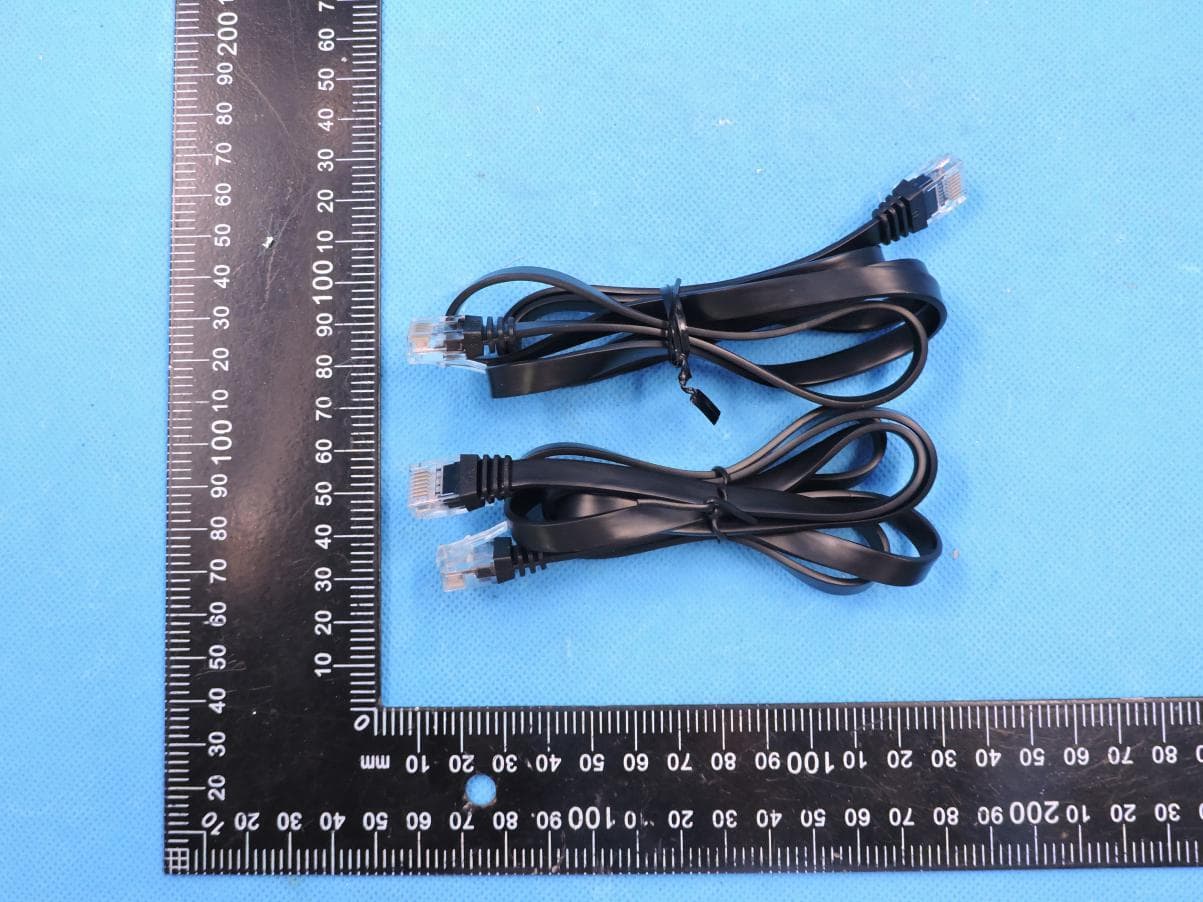
T58M6R
Jul 03, 2022AX1800 Whole Home Mesh WiFi 6 System
Equipment Class
NII - Unlicensed National Information Infrastructure TX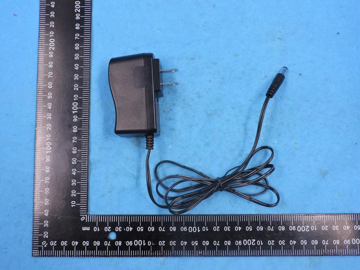
T58N6TR
Jun 05, 2022AX1800 Dual-Band Wireless Router
Equipment Class
DTS - Digital Transmission System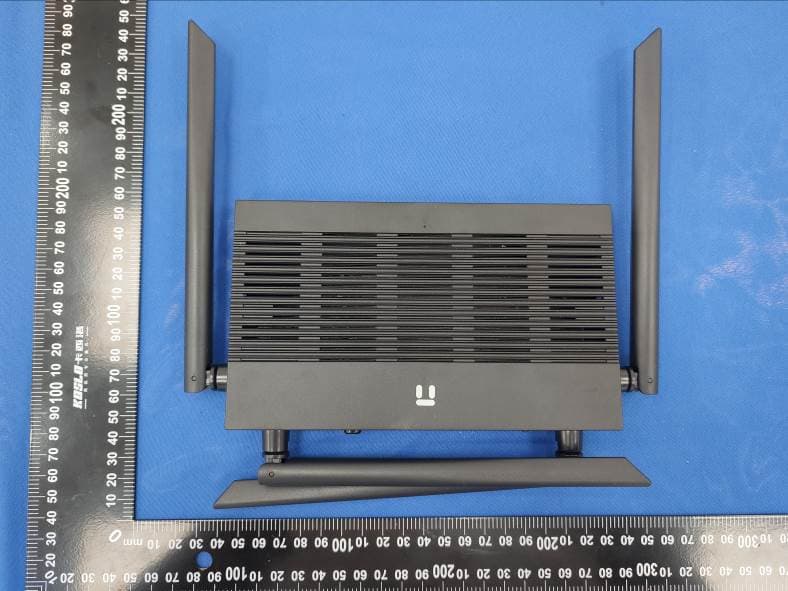
T58N3R
Sep 26, 2021AC1200 Wireless Dual Band Gigabit Router
Equipment Class
NII - Unlicensed National Information Infrastructure TX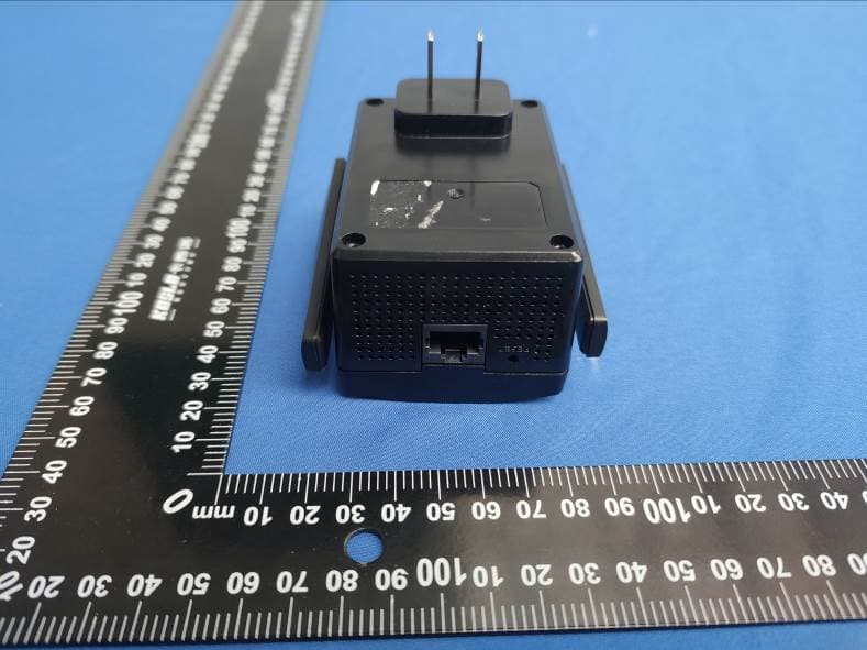
T58E3R
Jul 17, 2021AC1200 Dual Band WiFi Repeater
Equipment Class
DTS - Digital Transmission System