T68-BEACON100WiFi Location Tag
Fluke Electronics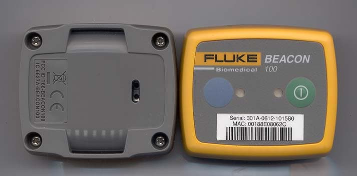
Click to zoom
Application Details
- Equipment Class
- DTS - Digital Transmission System
- Date of Grant
- Mar 04, 2007
- Application Purpose
- Original Equipment
- Date of Application
- Mar 04, 2007
- Equipment Note
- WiFi Location Tag
- Frequency Range
- 2412.00000000 - 2462.00000000
- Company
- Fluke Electronics
- Country
- United States
Documents & Files
Document Text
Text extracted from the exhibit documents filed with the FCC. Open a document above to read the original.
Users Manual
Fluke Biomedical Beacon100 Users Guide PN 2803836 January 2007 © 2007 Fluke Corporation, All rights reserved. Printed in USA All product names are trademarks of their respective companies. Warranty and Product Support Fluke Biomedical warrants this instrument against defects in materials and workmanship for one full year from the date of original purchase. During the warranty period, we will repair or, at our option, replace at no charge a product that proves to be defective, provided you return the product, shipping prepaid, to Fluke Biomedical. This warranty does not apply if the product has been damaged by accident or misuse or as the result of service or modification by other than Fluke Biomedical. IN NO EVENT SHALL FLUKE BIOMEDICAL BE LIABLE FOR CONSEQUENTIAL DAMAGES. Only serialized products and their accessory items (those products and items bearing a distinct serial number tag) are covered under this one–year warranty. PHYSICAL DAMAGE CAUSED BY MISUSE OR PHYSICAL ABUSE IS NOT COVERED UNDER THE WARRANTY. Items such as cables and nonserialized modules are not covered under this warranty. Recalibration of instruments is not covered under the warranty. This warranty gives you specific legal rights, and you may also have other rights which vary from state to state, province to province, or country to country. This warranty is limited to repairing the instrument to Fluke Biomedical’s specifications. Warranty Disclaimer Should you elect to have your instrument serviced and/or calibrated by someone other than Fluke Biomedical, please be advised that the original warranty covering your product becomes void when the tamper-resistant Quality Seal is removed or broken without proper factory authorization. We strongly recommend, therefore, that you send your instrument to Fluke Biomedical for factory service and calibration, especially during the original warranty period. Notices All Rights Reserved © Copyright 2006, Fluke Biomedical. No part of this publication may be reproduced, transmitted, transcribed, stored in a retrieval system, or translated into any language without the written permission of Fluke Biomedical. Copyright Release Fluke Biomedical agrees to a limited copyright release that allows you to reproduce manuals and other printed materials for use in service training programs and other technical publications. If you would like other reproductions or distributions, submit a written request to Fluke Biomedical. Unpacking and Inspection Follow standard receiving practices upon receipt of the instrument. Check the shipping carton for damage. If damage is found, stop unpacking the instrument. Notify the carrier and ask for an agent to be present while the instrument is unpacked. There are no special unpacking instructions, but be careful not to damage the instrument when unpacking it. Inspect the instrument for physical damage such as bent or broken parts, dents, or scratches. Technical Support For application support or answers to technical questions, either email [email protected] or call 1-800- 648-7952 or 1- 425-446-6945. Claims Our routine method of shipment is via common carrier, FOB origin. Upon delivery, if physical damage is found, retain all packing materials in their original condition and contact the carrier immediately to file a claim. If the instrument is delivered in good physical condition but does not operate within specifications, or if there are any other problems not caused by shipping damage, please contact Fluke Biomedical or your local sales representative. Standard Terms and Conditions Refunds and Credits Please note that only serialized products and their accessory items (i.e., products and items bearing a distinct serial number tag) are eligible for partial refund and/or credit. Nonserialized parts and accessory items (e.g., cables, carrying cases, auxiliary modules, etc.) are not eligible for return or refund. Only products returned within 90 days from the date of original purchase are eligible for refund/credit. In order to receive a partial refund/credit of a product purchase price on a serialized product, the product must not have been damaged by the customer or by the carrier chosen by the customer to return the goods, and the product must be returned complete (meaning with all manuals, cables, accessories, etc.) and in “as new” and resalable condition. Products not returned within 90 days of purchase, or products which are not in “as new” and resalable condition, are not eligible for credit return and will be returned to the customer. The Return Procedure (see below) must be followed to assure prompt refund/credit. Restocking Charges Products returned within 30 days of original purchase are subject to a minimum restocking fee of 15 %. Products returned in excess of 30 days after purchase, but prior to 90 days, are subject to a minimum restocking fee of 20 %. Additional charges for damage and/or missing parts and accessories will be applied to all returns. Return Procedure All items being returned (including all warranty-claim shipments) must be sent freight-prepaid to our factory location. When you return an instrument to Fluke Biomedical, we recommend using United Parcel Service, Federal Express, or Air Parcel Post. We also recommend that you insure your shipment for its actual replacement cost. Fluke Biomedical will not be responsible for lost shipments or instruments that are received in damaged condition due to improper packaging or handling. Use the original carton and packaging material for shipment. If they are not available, we recommend the following guide for repackaging: Use a double–walled carton of sufficient strength for the weight being shipped. Use heavy paper or cardboard to protect all instrument surfaces. Use nonabrasive material around all projecting parts. Use at least four inches of tightly packed, industry-approved, shock-absorbent material around the instrument. Returns for partial refund/credit: Every produ…
Text truncated - open the document above for the full version.
ID Label/Location Info
1(1) Marking and location BEACON100
Test Report
Intertek Semko AB Torshamnsgatan 43, Box 1103, SE-164 22 Kista, Sweden Telephone +46 8 750 00 00, Fax +46 8 750 60 30, www.sweden.intertek-etlsemko.com Registered in Sweden: No SE556024059901, Registered office: As address r d f n c Test report no. 605178R-2 Page 2 (37) CONTENTS Page 1 Client information ............................................................................................................... 3 2 Equipment under test (EUT) .............................................................................................. 3 2.1 Identification of the EUT according to the manufacturer/client declaration .... 3 2.2 Additional information about the EUT............................................................. 3 2.3 Test specifications .......................................................................................... 4 2.4 Standards ....................................................................................................... 4 2.5 Additions, deviations and exclusions from standards..................................... 4 2.6 Test set-up...................................................................................................... 4 2.7 Operating environment ................................................................................... 4 3 Test summary..................................................................................................................... 5 4 Peak output power .............................................................................................................6 4.1 Test protocol ................................................................................................... 6 5 6 dB Bandwidth ................................................................................................................ 10 5.1 Test protocol ................................................................................................. 10 6 Band edge compliance, conducted .................................................................................. 14 6.1 Test protocol ................................................................................................. 14 7 Power spectral density ..................................................................................................... 16 7.1 Test protocol ................................................................................................. 16 8 Radiated spurious emissions ........................................................................................... 20 8.1 Measurement uncertainty ............................................................................. 20 8.2 Test equipment ............................................................................................. 20 8.3 Measurement set-up..................................................................................... 21 8.4 Test protocol ................................................................................................. 23 9 Duty Cycle ........................................................................................................................ 36 10 Appendix I – Photos of the EUT....................................................................................... 37 Intertek Semko AB Torshamnsgatan 43, Box 1103, SE-164 22 Kista, Sweden Telephone +46 8 750 00 00, Fax +46 8 750 60 30, www.sweden.intertek-etlsemko.com Registered in Sweden: No SE556024059901, Registered office: As address r d f n c Test report no. 605178R-2 Page 3 (37) 1 CLIENT INFORMATION The EUT has been tested by request of Company: Ekaha Inc. Tallberginkatu 2 00180 Helsinki FINLAND Name of contact: Arttu Huhtiniemi 2 EQUIPMENT UNDER TEST (EUT) 2.1 Identification of the EUT according to the manufacturer/client declaration Equipment: Tag Type / Model: T301-A Brand name: -- Serial number: -- Manufacturer: Ekahau Inc. Rating/Supplying voltage: Battery operated 3,0 V Lithium CR2 Rating RF output power: 2dBm Antenna gain: 1,5 dBi External antenna connector: None Operating temperature range: -20 to +55 °C Frequency range: 2400 - 2483,5 MHz Number of channels: 11 Modulation characteristics: DSSS (QPSK) Stand by mode supported: Yes Low channel = 1 2412 MHz Mid channel = 6 2437 MHz High channel = 11 2462 MHz 2.2 Additional information about the EUT The EUT were temporally equipped with an antenna connector (standard SMA) for the conducted measurements. Intertek Semko AB Torshamnsgatan 43, Box 1103, SE-164 22 Kista, Sweden Telephone +46 8 750 00 00, Fax +46 8 750 60 30, www.sweden.intertek-etlsemko.com Registered in Sweden: No SE556024059901, Registered office: As address r d f n c Test report no. 605178R-2 Page 4 (37) 2.3 Test specifications 2.4 Standards FCC 47 CFR part 15 (2005) Subpart B – Unintentional radiators FCC 47 CFR part 15 (2005) Subpart C – Intentional Radiators; §15.247 Operation within the bands 902-928 MHz, 2400 – 2483.5 MHz and 5725 – 5850 MHz. Measurements methods according to ANSI C63.4-2003 RSS-210, Issue 6 (September 2005): Low Power Licence-Exempt Radiocommunication Devices (All Frequency Bands): Category I Equipment. RSS-Gen, Issue 1 (September 2005): General Requirements and Information for the Certification of Radiocommunication Equipment. 2.5 Additions, deviations and exclusions from standards No additions, deviations or exclusions have been made from standards. 2.6 Test set-up Measurement set-up radiated spurious emissions test is described in corresponding section. During other tests the EUT was connected to the spectrum analyser by cable. 2.7 Operating environment If not additionally specified, the tests were performed under the following environmental conditions: Air temperature: 23 °C Relative humidity: 33 % Intertek Semko AB Torshamnsgatan 43, Box 1103, SE-164 22 Kista, Sweden Telephone +46 8 750 00 00, Fax +46 8 750 60 30, www.sweden.intertek-etlsemko.com Registered in Sweden: No SE556024059901, Registered office: As address r d f n c Test report no. 605178R…
Text truncated - open the document above for the full version.
Test Setup Photos
1(1) TEST SET-UP PHOTOS MODEL: T301-A Radiated spurious emission 30-1000 MHz Radiated spurious emission 1-26 GHz
Contact Information
Applicant
James E Lenker(Test Engineer)
Technical Contact
Ekahau, Inc.Arttu E Huhtiniemi
[email protected]+358 20 743 5910
Tallberginkatu 2 A · Helsinki · Finland
Non-Technical Contact
Ekahau, Inc.Salla Heino
[email protected]+358 20 743 5910
Test Firm
Intertek SEMKO ABNiklas Bostrom
Technical Specifications
| # | Rule Parts | Frequency Range | Power Output |
|---|---|---|---|
| 1 | 15C | 2.41 GHz - 2.46 GHz | 1.00 mW |
Other Applications from Fluke Electronics
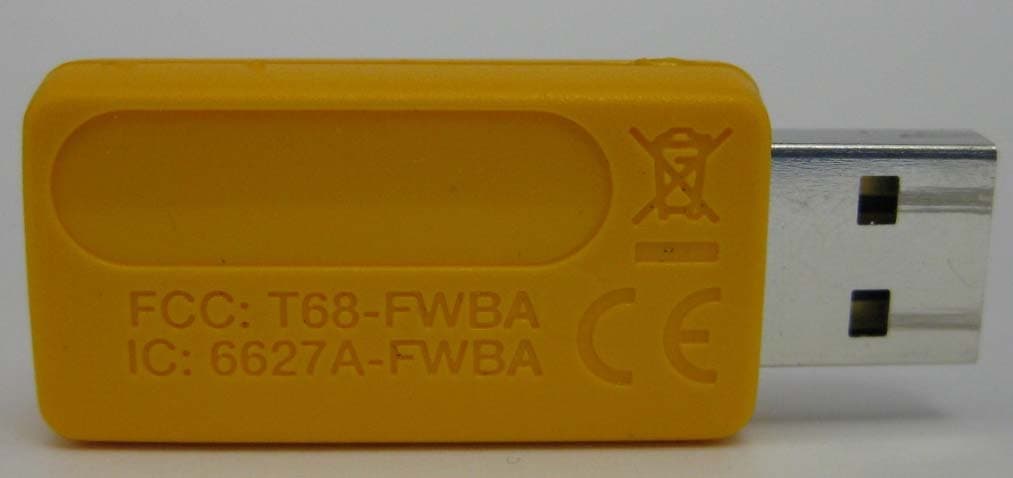
T68-FWBA
Oct 27, 2015USB1 FC WiFi-BLE Adapter
Equipment Class
DTS - Digital Transmission System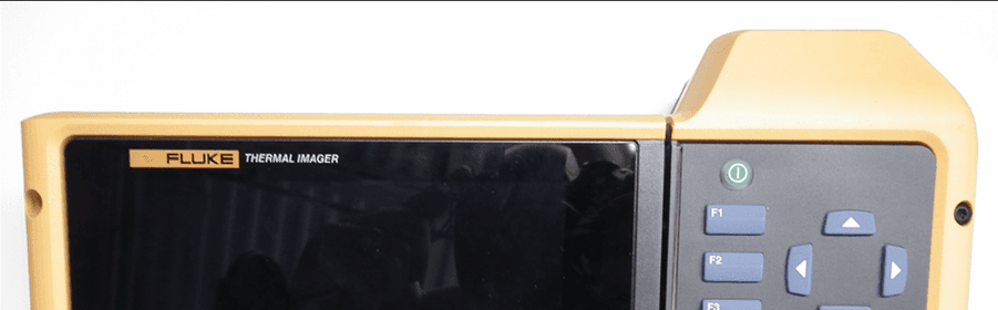
T68-FT560
May 14, 2015TiX560, TiX520
Equipment Class
DSS - Part 15 Spread Spectrum Transmitter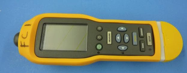
T68-805FC
May 10, 2015Vibration Meter
Equipment Class
DSS - Part 15 Spread Spectrum TransmitterT68-FBLE
Oct 27, 2013Radio Module
Equipment Class
DSS - Part 15 Spread Spectrum Transmitter
T68-FT400
Sep 29, 2013Gemini
Equipment Class
DTS - Digital Transmission System