T68-FWBAUSB1 FC WiFi-BLE Adapter
Fluke Electronics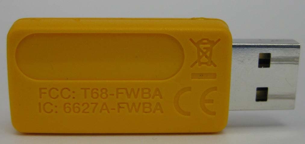
Click to zoom
Application Details
- Equipment Class
- DTS - Digital Transmission System
- Date of Grant
- Oct 27, 2015
- Application Purpose
- Original Equipment
- Date of Application
- Oct 26, 2015
- Equipment Note
- USB1 FC WiFi-BLE Adapter
- Frequency Range
- 2402.00000000 - 2480.00000000
- Company
- Fluke Electronics
- Country
- United States
Documents & Files
Document Text
Text extracted from the exhibit documents filed with the FCC. Open a document above to read the original.
Users Manual
WIFI-BLE Adapter USB1 FC For use with 17xx FC models SymbolDefinition Conforms to European Union directives Conforms to relevant Australian EMC requirements This product complies with the WEEE Directive (2002/96/ EC) marking requirements. The affixed label indicates that you must not discard this electrical/electronic product in domestic household waste. Product Category: With reference to the equipment types in the WEEE Directive Annex I, this product is classed as Category 9 “Monitoring and Control Instrumentation” product. Do not dispose of this product as unsorted municipal waste. Go to Fluke’s website for recycling information. LIMITED WARRANTY AND LIMITATION OF LIABILITY This Fluke product will be free from defects in material and workmanship for three years from the date of purchase. This warranty does not cover fuses, disposable batteries, or damage from accident, neglect, misuse, alteration, contamination, or abnormal conditions of operation or handling. Resellers are not authorized to extend any other warranty on Fluke’s behalf. To obtain service during the warranty period, contact your nearest Fluke authorized service center to obtain return authorization information, then send the product to that Service Center with a description of the problem. THIS WARRANTY IS YOUR ONLY REMEDY. NO OTHER WARRANTIES, SUCH AS FITNESS FOR A PARTICULAR PURPOSE, ARE EXPRESSED OR IMPLIED. FLUKE IS NOT LIABLE FOR ANY SPECIAL, INDIRECT, INCIDENTAL OR CONSEQUENTIAL DAMAGES OR LOSSES, ARISING FROM ANY CAUSE OR THEORY. Since some states or countries do not allow the exclusion or limitation of an implied warranty or of incidental or consequential damages, this limitation of liability may not apply to you. Installation instructions 6/2015 ©2015 Fluke Corporation. Specifications subject to change without notice. Printed in Romania. Made in Taiwan. www.fluke.com Fluke Corporation P.O. Box 9090 Everett, WA 98206-9090 Fluke Europe B.V. P.O. Box 1186 5602 BD Eindhoven, The Netherlands Made in Taiwan. FCC: T68-FWBA IC: 6627A-FWBA See inside of this card for warranty information. Go to www.fluke.com to register your product and find more information. 2 1 3 4 5
Users Manual
PN 4584039 September 2015 © 2015 Fluke Corporation. All rights reserved. All product names are trademarks of their respective companies. USB1 FC WiFi-BLE Adapter Manual 1 Introduction This product is intended for use with Fluke test equipment only. Information about radio frequency data is subject to change without notice. For up-to-date information, go to www.fluke.com. Specifications Dimensions ............................................................ 50 mm x 17 mm x 8 mm Radio Interface ...................................................... 802.11 b/g, 2.4 GHz Software Interface ................................................. Linux device driver Other Interfaces .................................................... USB 2.0 Bluetooth Protocol ................................................ 4.0 LE (Bluetooth Smart Ready) Concurrent Wireless Modes ................................ WiFi and BLE Security .................................................................. WPA, WPA2 Data Transfer ......................................................... 12 Mbit/s Operating Temperature ........................................ 10 °C to 50 °C Storage Temperature ............................................ 20 °C to 60 °C USB1 FC Manual 2 FCC/IC Information • FCC ID: T68-FWBA Class A digital device: This equipment has been tested and found to comply with the limits for a Class A digital device, pursuant to Part 15 of the FCC Rules. Operation is subject to the two conditions that follow: (1) this device can not cause interference and (2) this device must accept any interference, including interference that can cause undesired operation of the device. These limits are designed to provide reasonable protection against harmful interference when the equipment is operated in a commercial environment. This equipment generates, uses, and can radiate radio frequency energy, and if it is not installed and used in accordance with the instruction manual, it may cause harmful interference to radio communications. Operation of this equipment in a residential area is likely to cause harmful interference, in which case the user will be required to correct the interference at his own expense. The term “IC” before the radio certification number only signifies the device meets Industry’s Canada technical specifications. • IC: 6627A-FWBA Note Changes or modifications to the wireless 2.4 GHz radio not expressly approved by Fluke Corporation could void the user’s authority to operate the equipment. WiFi-BLE Adapter Manual 3 This device complies with Industry Canada license-exempt RSS standard(s). Operation is subject to the following two conditions: (1) this device may not cause interference, and (2) this device must accept any interference, including interference that may cause undesired operation of the device. Le présent appareil est conforme aux CNR d'Industrie Canada applicables aux appareils radio exempts de licence. L'exploitation est autorisée aux deux conditions suivantes : (1) l'appareil ne doit pas produire de brouillage, et (2) l'utilisateur de l'appareil doit accepter tout brouillage radioélectrique subi, même si le brouillage est susceptible d'en compromettre le fonctionnement. The radio transmitter has been approved by Industry Canada to operate only with the antenna supplied. Use of any other antenna is strictly prohibited for use with this product. L'émetteur radio a été approuvé par Industrie Canada pour fonctionner uniquement avec l'antenne fournie. L'utilisation de toute autre antenne est strictement interdit d'utiliser ce produit. USB1 FC Manual 4 MPE/SAR/RF Exposure Information MPE / SAR / RF Information sur l'Exposition This device was verified for RF exposure and found to comply with FCC OET-65 RF Exposure and RSS-102 requirements. This Product meets the SAR exemption based on its output power. Ce produit a été vérifiée pour l'exposition de puissance radio et jugé conforme aux normes FCC OET-65 et RSS-102 exigences. Sur la base de la puissance de sortie de la radio, ce produit répond aux taux d'absorption spécifique exemption. Country-Specific Information Brazil Este equipamento opera em caráter secundário, isto é, não tem direito a proteção contra interferência prejudicial, mesmo de estações do mesmo tipo, e não pode causar interferência a sistemas operando em caráter primário.” 0000-00-0000 0789 RRRRRRR PP D WiFi-BLE Adapter Manual 5 Mexico La operación de este equipo está sujeta a las siguientes dos condiciones: (1) es posible que este equipo o dispositivo no cause interferencia perjudicial y (2) este equipo o dispositivo debe aceptar cualquier interferencia, incluyendo la que pueda causar su operación no deseada. • IFETEL: XXXXXXXXX-ZZZZ S. Korea 당해 무선설비는 전파혼신 가능성이 있으므로 인명안전과 관련된 서비스는 할수 없음 • MSIP—CMM-FLK-XXXXXXXXX USB1 FC Manual 6 Taiwan 低功率電波輻性電機管理辦法第十二條經型式認證合格之低功率射頻電機, 非經許可,公司、商號或使用者均不得擅自變更頻率、加大功率或變更原設 計之特性及功能。第十四條低功率射頻電機之使用不得影響飛航安全及干擾 合法通信;經發現有干擾現象時,應立即停用,並改善至無干擾時方得繼續 使用。前項合法通信,指依電信規定作業之無線電信。低功率射頻電機須忍 受合法通信或工業、科學及醫療用電波輻射性電機設備之干擾。 警告使用者:這是甲類的資訊產品,在居住的環境中使用時,可能會造成射 頻干擾,在這種情況下,使用者會被要求採取某些適當的對策。 CCXXxxLPyyyZzW Thailand อุปกรณ์ด้านการโทรคมนาคมนี้เป็นไปตามข้อกําหนดด้านเทคนิค NTC • NTC XXXXXXXXX WiFi-BLE Adapter Manual 7 Argentina CNC: X-XXXX South Africa ICASA: XX-XXXX/XXX
Users Manual
Septemb er 2015 © 2015 Fluke Corporation. All rights reserved. Spec ifications are subject to change without notice. All product names are trademarks of their respective companies. 1736/1738 Power Logger Users Manual LIMITED WARRANTY AND LIMITATION OF LIABILITY Each Fluke product is warranted to be free from defects in mate rial and workmanship under normal use and service. The warranty period is two years and begins on the date of shipment. Parts, product repairs, and servic es are warranted for 90 days. This warranty extends only to t he original buyer or end-user customer of a Fluke authorized reseller, and does not apply to fuse s, disposable batteries, or to any product which, in Fluke's opinion, has been misused, altered, neglected, contaminated, or damaged by accident or abnor mal conditions of operation or han dling. Fluke warrants that s oftware will operate substantially in accordance with its func tional specifications for 90 days and that it has been properly recorded on non-defect ive media. Fluke does not warrant that software will be error free or operate without interruption. Fluke authorized resellers shall extend this warranty on new and unused products to end-user customers only but have no authori ty to extend a greater or different warranty on behalf of Fluke. Warranty support is ava ilable only if product is purchas ed through a Fluke authorized sa les outlet or Buyer has paid the applicable international price. Fluke reserv es the right to invoice Buyer for importa tion costs of repair/replacement parts whe n product purchased in one country is submitted for repair in another country. Fluke's warranty obligation is limited, at Fluke's option, to refund of the purchase pr ice, free of charge repair, or replaceme nt of a defective product which is returned to a Fluke authorized service center within the warranty period. To obtain warranty service, contact your ne arest Fluke authorized service center to ob tain return authorization information, th en send the product to that service center, with a description of the difficulty, postage and insurance prepaid (FOB Destination). Fluke assumes no risk fo r damage in transit. Following warranty repair, the product will be returned to Buyer, transport ation prepaid (FOB Destination). If Fluke determines that fail ure was caused by neglect, misuse, contamination, alteration, accident, or abnormal condi tion of operation or handling, including overvoltage failures cau sed by use outside the product’s specified rating, or normal wear and tear of mechanical com ponents, Fluke will provide an estima te of repair costs and obtain a uthorization before commencing the work. Following repair, the product will be returned to the Buyer transportation prepaid and the Buyer will be b illed for the repair and return transportation charges (FOB Shipping Point). THIS WARRANTY IS BUYER'S SOLE AND EXCLUSIVE REMEDY AND IS IN LIEU OF ALL OTHER WARRANTIES, EXPRESS OR IMPLIED, INCLUDING BUT NOT LIMITED TO ANY IMPLIED WARRANTY OF MERCHANTABILITY OR FITNESS FOR A PARTICULAR PURPOSE. FLUKE SHALL NOT BE LIABLE FOR ANY SPECIAL, INDIRECT, INCIDENT AL OR CONSEQUENTIAL DAMAGES OR LOSSES, INCLUDING LOSS OF DATA, ARISING FROM ANY CAUSE OR THEORY. Since some countries or states do not allow limitation of the term of an implied warranty, or exclusion or limitation of incide ntal or consequential damages, the limitations and exclusions of this warranty may not apply to every buyer. If any provis ion of this Warranty is held invalid or unenforceable by a court or other decision-maker of competent jurisdiction, such holding will not affect the validity or enforceability of any other provision. Fluke Corporation P.O. Box 9090 Everett, WA 98206-9090 U.S.A. Fluke Europe B.V. P.O. Box 1186 5602 BD Eindhoven The Netherlands 11/99 To register your product online, visit register.fluke.com . i Table of Contents Title Page Introduc tion .................................................................................................................. .. 1 How to Contac t Fluke .................................................................................................... 2 Safety Information .......................................................................................................... 2 Before You Start ............................................................................................................ 5 WiFi and WiFi/BLE-to-USB Adapter .......................................................................... 6 Magnet Hanger Kit .................................................................................................... 7 Voltage Test Leads ................................................................................................... 7 Thin-Flexi Curr ent Probe ........................................................................................... 8 Kensington Lock ....................................................................................................... 9 Accessori es ................................................................................................................... 10 Storage ....................................................................................................................... ... 11 Tilt Stand .................................................................................................................... ... 11 Power Su pply ................................................................................................................ 11 How to Charge Battery .................................................................................................. 12 Navigation and User Interfac e ....................................................................................... 13 Applying the Connecto r Panel De cal ........................................................................ 15 Power ON/O FF .......................................................................…
Text truncated - open the document above for the full version.
Cover Letter(s)
Authority to Act as Agent Date: August 13, 2015 American Certification Body, Inc. 6731 Whittier Avenue Suite C110 McLean, VA 22101 To Whom It May Concern: Thomas T. Smith, Ryan Urness and Amanda Hauck of LS Research, LLC is authorized to act on our behalf, until otherwise notified, for applications to American Certification Body, Inc. (ACB). We certify that we are not subject to denial of federal benefits, that includes FCC benefits, pursuant to Section 5301 of the Anti-Drug Abuse Act of 1988, 21 U.S.C. 862. Further, no party, as defined in 47 CFR 1.2002 (b), to the application is subject to denial of federal benefits, that includes FCC benefits. The term of this Agency Agreement shall start on the above date of this Agreement and shall continue in force until one (1) year thereafter. Thank you, By: James E Lenker Title: Staff Engineer On behalf of: ______Fluke Corporation Telephone: _425 446 5929
Cover Letter(s)
Request for Confidentiality Date: August 13, 2015 Confidentiality Request for: FCC ID:T68-FWBA IC ID: 6627A-FWBA To Whom It May Concern, Pursuant to FCC 47 CRF 0.457(d) and 0.459 and IC RSP-100, Section 6.4, the applicant requests that a part of the subject FCC and/or IC application be held confidential. The applicant requests the exhibits listed below be permanently withheld from public review due to materials that contain trade secrets and proprietary information not customarily released to the public. Block Diagram Schematics Applicant has spent substantial effort in developing this product and it is one of the first of its kind in industry. Having the subject information easily available to "competition" would negate the advantage they have achieved by developing this product. Not protecting the details of the design will result in financial hardship. Sincerely, (Signature) Name :James E Lenker Title: Product Compliance Engineer Phone:425 446 5929 Email: [email protected]
Cover Letter(s)
Date: October 28, 2015 American Certification Body, Inc. 6731 Whittier Avenue Suite C110 McLean, VA 22101 To Whom It May Concern: Regarding the USB1 FC Wi-Fi BLE adapter. Fluke is aware that classic Bluetooth is not an allowable mode of operation in all products that host the adapter. The classic Bluetooth mode (BR and EDR) will not be available in all Fluke test instrument host products that use the adapter. The host firmware that resides inside a Fluke test instrument limits the Bluetooth mode of operation to Bluetooth low energy only, the adapter will not operate or transmit without the firmware in the host, so Bluetooth low energy is the only mode of Bluetooth operation. . Thank you, By: James E Lenker Product compliance Engineer Fluke Corporation 6920 Seaway Blvd. Everett Washington 98203 Telephone: _425 446 5929
External Photos
EXTERNAL PHOTOS Company Name Fluke Corporation Model # USB1 FC FCC ID # T68‐FWBA IC # 6627A‐FWBA Page 1 of 1
ID Label/Location Info
Page 1 of 1
Internal Photos
INTERNAL PHOTOS Company Name Fluke Corporation Model # USB1 FC FCC ID # T68‐FWBA IC # 6627A‐FWBA Page 1 of 5 INTERNAL PHOTOS Company Name Fluke Corporation Model # USB1 FC FCC ID # T68‐FWBA IC # 6627A‐FWBA Page 2 of 5 INTERNAL PHOTOS Company Name Fluke Corporation Model # USB1 FC FCC ID # T68‐FWBA IC # 6627A‐FWBA Page 3 of 5 INTERNAL PHOTOS Company Name Fluke Corporation Model # USB1 FC FCC ID # T68‐FWBA IC # 6627A‐FWBA Page 4 of 5 INTERNAL PHOTOS Company Name Fluke Corporation Model # USB1 FC FCC ID # T68‐FWBA IC # 6627A‐FWBA Page 5 of 5
Operational Description
(1/5) 001-01 / 20130901 / rf_ant_ant016008lcd2442ma1_en.fm • All specifications are subject to change without notice. Multilayer Chip Antennas For IEEE802.11a/b/g/n ANT Series ANT016008LCD2442MA1 SHAPES AND DIMENSIONS Conformity to RoHS Directive Halogen-free 1.6 ( 0.1 ) ( 0.1 ) 0.085±0.085 B1A B2 0.4max. 0.8 0.628 0.086±0.086 0.2150.2150.5 0.25 0.25 Dimensions in mm A: Feed point B1: Radiator electrode for 2.4GHz B2: Radiator electrode for 5.5GHz Tolerance: ±0.1 mm •Conformity to RoHS Directive: This means that, in conformity with EU Directive 2002/95/EC, lead, cadmium, mercury, hexavalent chromium, and specific bromine-based flame retardants, PBB and PBDE, have not been used, except for exempted applications. •Halogen-free: Indicates that Cl content is less than 900ppm, Br content is less than 900ppm, and that the total Cl and Br content is less than 1500ppm. (2/5) 001-01 / 20130901 / rf_ant_ant016008lcd2442ma1_en.fm • All specifications are subject to change without notice. RECOMMENDED PC BOARD PATTERNS ELECTRODE Front side Back side SOLDER RESIST Front side RECOMMEND APERTURE SIZE OF METAL MASK FOR SOLDER PRINTING 6.561.160.140.14 3 8 0.650Ω feed lineMt: Matching tuning 0.65 0.4 0.65 0.25 0.21 0.364 5 Ft 2.4GHz : Frequency tuning for 2.4GHz Ft 5.5GHz : Frequency tuning for 5.5GHz GND GND 0.6 0.9 1.8 B1 B2 Dimensions in mm 0.364 5.660.14 0.555 3 8 0.65 0.25 5 GND 1.17 5-ø0.2 1.17×4 ( =4.68 ) Dimensions in mm Center line of chip antenna Chip antenna Matching component GND clearance Via 7.863.07 0.3 1.53 0.8 0.5 1.2 0.5750.65 5.35 9.325 9.7 0.3 0.65 0.728 0603 size 0603 size For 0603 size For chip antenna For 1005 size Chip antenna 1005 size Dimensions in mm 0.4 1.1 1.43 0.3 0.6 Aperture of metal mask Dimensions in mm (3/5) 001-01 / 20130901 / rf_ant_ant016008lcd2442ma1_en.fm • All specifications are subject to change without notice. ELECTRICAL CHARACTERISTICS • This is typical antenna performance with the standard PCB. FREQUENCY CHARACTERISTICS EFFICIENCY AND VSWR IEEE802.11b/g/nIEEE802.11a Center frequency (F11b/g/n, F11a) F 11b/g/n 2442MHz, F 11a 5500MHz Band width(BW) (F11b/g/n, F11a) F11b/g/n ±42MHz, F11a ±350MHz VSWR (at BW) (F11b/g/n, F11a) F11b/g/n 6.5max. F11a 4max. PolarizationLinear Impedance50 PCB size120651.0mm Temperature range Operating–40 to +85°C Storage–40 to +85°C –10 –9 –8 –6 –7 –3 –4 –1 –5 –2 0 Efficiency ( dB ) 1 11 10 9 8 7 6 5 4 3 2 VSWR Frequency ( GHz ) 2.302.352.402.452.502.55 2.60 Matching circuit Ft: 2.4GHz: 2.5pF Ft: 5.5GHz: 0.3pF Mt: 1.5nH Total efficiency VSWR –10 –9 –8 –6 –7 –3 –4 –1 –5 –2 0 Efficiency ( dB ) 1 11 10 9 8 7 6 5 4 3 2 VSWR Frequency ( GHz ) 5.005.205.405.605.80 6.00 Matching circuit Ft: 2.4GHz: 2.5pF Ft: 5.5GHz: 0.3pF Mt: 1.5nH Total efficiency VSWR (4/5) 001-01 / 20130901 / rf_ant_ant016008lcd2442ma1_en.fm • All specifications are subject to change without notice. RADIATION PATTERNS IEEE802.11b/g/n • Tested antenna has been soldered. Evaluation board size is 120×65×1 mm. Directivity angleVertical polarizationHorizontal polarization 270 ̊90 ̊ 0 ̊ X Y Z 180 ̊ 270 ̊ 315 ̊ 135 ̊ 45 ̊ 225 ̊ 90 ̊ 0 –10 10 ( dBi ) –20 –30 –40 0 ̊ Vertical polarization Frequency ( GHz ) Average ( dBi ) Maximum ( dBi ) Minimum ( dBi ) 2.400 –9.62 –2.82 –36.90 2.442 –8.45 –1.44 –34.11 2.485 –10.13 –3.02 –32.46 2.400GHz 2.442GHz 2.485GHz 180 ̊ 270 ̊ 315 ̊ 135 ̊ 45 ̊ 225 ̊ 90 ̊ 0 –10 10 ( dBi ) –20 –30 –40 0 ̊ Horizontal polarization 2.400GHz 2.442GHz 2.485GHz Frequency ( GHz ) Average ( dBi ) Maximum ( dBi ) Minimum ( dBi ) 2.400 –7.06 –2.18 –27.38 2.442 –5.44 –0.48 –44.31 2.485 –6.82 –1.94 –29.46 270 ̊ 90 ̊ 0 ̊ Y X Z 180 ̊ 270 ̊ 315 ̊ 135 ̊ 45 ̊ 225 ̊ 90 ̊ 0 –10 10 ( dBi ) –20 –30 –40 0 ̊ Vertical polarization Frequency ( GHz ) Average ( dBi ) Maximum ( dBi ) Minimum ( dBi ) 2.400 –21.03 –13.19 –48.22 2.442 –19.00 –12.04 –46.88 2.485 –20.43 –12.29 –40.26 2.400GHz 2.442GHz 2.485GHz 180 ̊ 270 ̊ 315 ̊ 135 ̊ 45 ̊ 225 ̊ 90 ̊ 0 –10 10 ( dBi ) –20 –30 –40 0 ̊ Horizontal polarization 2.400GHz 2.442GHz 2.485GHz Frequency ( GHz ) Average ( dBi ) Maximum ( dBi ) Minimum ( dBi ) 2.400 –5.81 0.54 –26.20 2.442 –4.32 2.27 –27.25 2.485 –5.70 1.19 –22.01 270 ̊ 90 ̊ 0 ̊ Y Z X 180 ̊ 270 ̊ 315 ̊ 135 ̊ 45 ̊ 225 ̊ 90 ̊ 0 –10 10 ( dBi ) –20 –30 –40 0 ̊ Vertical polarization Frequency ( GHz ) Average ( dBi ) Maximum ( dBi ) Minimum ( dBi ) 2.400 –3.21 –0.54 –7.87 2.442 –1.68 0.98 –6.33 2.485 –3.18 –0.23 –7.97 2.400GHz 2.442GHz 2.485GHz 180 ̊ 270 ̊ 315 ̊ 135 ̊ 45 ̊ 225 ̊ 90 ̊ 0 –10 10 ( dBi ) –20 –30 –40 0 ̊ Horizontal polarization 2.400GHz 2.442GHz 2.485GHz Frequency ( GHz ) Average ( dBi ) Maximum ( dBi ) Minimum ( dBi ) 2.400 –17.05 –11.24 –48.22 2.442 –15.74 –9.64 –51.80 2.485 –17.47 –11.46 –40.53 (5/5) 001-01 / 20130901 / rf_ant_ant016008lcd2442ma1_en.fm • All specifications are subject to change without notice. RADIATION PATTERNS IEEE802.11a • Tested antenna has been soldered. Evaluation board size is 120×65×1 mm. Directivity angleVertical polarizationHorizontal polarization 270 ̊90 ̊ 0 ̊ X Y Z 180 ̊ 270 ̊ 315 ̊ 135 ̊ 45 ̊ 225 ̊ 90 ̊ 0 –10 10 ( dBi ) –20 –30 –40 0 ̊ Vertical polarization Frequency ( GHz ) Average ( dBi ) Maximum ( dBi ) Minimum ( dBi ) 5.150 –7.05 0.04 –27.83 5.500 –7.06 0.89 –26.31 5.850 –7.32 0.31 –30.64 5.150GHz 5.500GHz 5.850GHz 180 ̊ 270 ̊ 315 ̊ 135 ̊ 45 ̊ 225 ̊ 90 ̊ 0 –10 10 ( dBi ) –20 –30 –40 0 ̊ Horizontal polarization Frequency ( GHz ) Average ( dBi ) Maximum ( dBi ) Minimum ( dBi ) 5.150 –2.39 4.22 –42.06 5.500 –2.73 4.78 –29.06 5.850 –3.25 3.29 –34.55 5.150GHz 5.500GHz 5.850GHz 270 ̊ 90 ̊ 0 ̊ Y X Z 180 ̊ 270 ̊ 315 ̊ 135 ̊ 45 ̊ 225 ̊ 90 ̊ 0 –10 10 ( dBi ) –20 –30 –40 0 ̊ Vertical polarization Frequency ( GHz ) Average ( dBi ) Maximum ( dBi ) Minimum ( dBi ) 5.150 –17.92 –9.40 –42.06 5.500 –15.62 –6.43 –37.80 5.850 –15.19 –7.73 –33.50 5.150GHz 5.500GHz 5.850GHz 180 ̊ 270 ̊ 315 ̊ 135 ̊ 45 ̊ 225 ̊ 90 ̊ 0 –10 10 ( dBi ) –20 –30 –40 0 ̊ Horizontal polarization Frequency ( GHz ) Average ( dBi ) Maximum ( dBi ) Minimum ( dBi ) 5.150 –2.74 5.18 –15.95 5.500 –3.…
Text truncated - open the document above for the full version.
Operational Description
The USB1 FC is a WiFi & BLE wireless to USB adapter to be used in test and measurement equipment such as the 1735 Energy Logger to communicate readings wirelessly. The adapter is placed inside the instrument and the instrument is left to record voltage and current over a period of time. The adapter will host the STM32 microcontroller along with the TI WL1831 radio module. The STM32 will act as a USB to SDIO and USB to UART bridge between the host Fluke product and the WL1831 radio module. The unit is powered via a 5V USB connector and utilizes a TDK chip antenna with Peak Gain in 2.4GHz band = 2.27 dBi The USB1 FC is intended for use only inside a Fluke test instrument and is not a general purpose adapter for use with a PC. It will not operate or transmit without the host firmware so it cannot be operated when connected to a PC The host firmware that resides inside a Fluke test instrument limits the BT mode of operation to BLE only. It will not operate or transmit without the host firmware so BLE is the only mode of BT operation. Microprocessor Number: ST Micro STM32F427IH6 Transceiver Number: TI WL1831MOD
Operational Description
Fluke Corporation Telephone Facsimile Email PO Box 9090 Everett WA 98206.9090 USA 425.347.6100 425.356.5108 http//www.fluke.com Date: August 11, 2015 To Whom It May Concern Regarding: Methods used for limiting WLAN transmit frequency range in the USB1 FC Wireless adapter The purpose of this letter is to describe the methods used to limit the operating frequency of the WLAN transmitter in the Fluke USB1 FC wireless adapter. The operating channels are limited to channels 1 through 11 the 2.4GHz ISM band for 20MHz channel bandwidth, 1 through 7 for 40MHz high channel bandwidth, and 5 through 11 for 40MHz low channel bandwidth. These channel limitation are enforced using the following methods: Restricted access to WLAN configuration tools: As the device is configured from the factory, it is impossible for any third party (users, installers, integrators, service personnel, etc.) to gain access to any parameters through the user interface which can configure the device to operate on WiFi channels 12, 13, or 14. Furthermore, Fluke provides no means for a third party to configure the device through an authorized software modification or by network configuration to allow the device to operate on WiFi channels 12, 13, or 14. The only known means to access to the parameters that configure access to WiFi channels 12, 13, or 14 is restricted through the use of an SSL cryptographic key, which is only provided to authorized personnel. Use of the Linux Central Regulatory Domain Agent (CRDA) to enforce FCC regulatory permissions: The host for the USB1 FC uses the Linux operating system, and implements CRDA to enforce FCC regulatory permissions. The wireless core driver (cfg80211) will only be allowed to initiate transmission on a given channel if the entire channel bandwidth is contained within the frequency range defined by the CRDA. For the USB1 FC, the allowed frequency range is coded in the firmware as a minimum 2402 MHz and a maximum of 2472 MHz. For each operating mode, cfg80211 will only enable channels that fall completely within this range, Tables 1-3 define the enabled and disabled channels for the 20 MHz (HT20), 40 MHz low , (HT40-) and 40 MHz high, (HT40+) operating modes Fluke Corporation Telephone Facsimile Email PO Box 9090 Everett WA 98206.9090 USA 425.347.6100 425.356.5108 http//www.fluke.com Fluke Corporation Telephone Facsimile Email PO Box 9090 Everett WA 98206.9090 USA 425.347.6100 425.356.5108 http//www.fluke.com A detailed description of the processing rules applied by the CRDA is available here: https://wireless.wiki.kernel.org/en/developers/regulatory/processing_rules Sincerely, James E. Lenker Product compliance Engineer Fluke Corporation 6920 Seaway Blvd. 425 446 5929 Everett Wa. 98203 USA
RF Exposure Info
W66 N220 Commerce Court ● Cedarburg, WI 53012 Phone: 262.375.4400 ● Fax: 262.375.4248 www.lsr.com SAR Test Exclusion Exhibit For: Fluke USB1 FC WIFI-BLE ADAPTER Prepared by: Adam Alger, EMC Engineer 8-11-15 W66 N220 Commerce Court ● Cedarburg, WI 53012 ● www.lsr.com Contents Product Description: ..................................................................................................................................... 3 Associated Antenna(s): ................................................................................................................................. 5 Statement of compliance: ............................................................................................................................. 5 Separation Distance: ..................................................................................................................................... 6 APPENDIX A –Bluetooth and WLAN Coexistence ................................................................................. 9 W66 N220 Commerce Court ● Cedarburg, WI 53012 ● www.lsr.com Product Description: The USB1 FC is a Wi Fi and Bluetooth low energy wireless to USB adapter to be used in test and measurement instruments such as the 1735 Energy Logger to communicate readings wirelessly: http://en-us.fluke.com/products/power-and-energy-loggers/fluke-1735-power-quality.html The Adapter is placed inside the instrument as shown in the photo and the instrument is left to record voltage and current over a period of time. Note: Bluetooth and WLAN radios do not transmit at the same time. Please refer to Appendix A for BT and WLAN Coexistence information. W66 N220 Commerce Court ● Cedarburg, WI 53012 ● www.lsr.com Typical application for the EUT W66 N220 Commerce Court ● Cedarburg, WI 53012 ● www.lsr.com Associated Antenna(s): The antenna used by the EUT is a TDK multilayer chip antenna, ANT016008LCD2442MA1 with a peak gain of 2.27 dBi. Statement of compliance: The Fluke USB1 FC WIFI-ADAPTER was evaluated against the SAR test exclusion threshold listed in KDB 447498 D01 General RF Exposure Guidance v05r02 for 10-g extremity at a distance of 5mm as well as RSS-102 Issue 5 for limb-worn at a distance of 15mm. W66 N220 Commerce Court ● Cedarburg, WI 53012 ● www.lsr.com Separation Distance: The EUT was evaluated against the SAR test exclusion threshold listed in KDB 447498 D01 General RF Exposure Guidance v05r02, section 4.3 (1). The EUT was found to be compliant with the SAR exclusion threshold, 10-g extremity, for 100MHz to 6000MHz. Note that the measured output power of the EUT is equivalent to the target output level. Frequency = 2.412GHz ERP (dBm) = 11.5dBm + 2.0 dBm (manufacturing tolerance) = 13.5dBm ERP (mW)= 22.4 milliwatt Minimum separation distance = 5mm [22.4mw/5mm]*[ √2.412GHz] = 4.48*1.55 =6.9 ≤ 7.5 When evaluated against RSS 102 issue 5 section 2.5, table 1: Frequency = 2.412GHz EIRP (dBm) = 11.5dBm + 2.3dBi + 2.0 dBm (manufacturing tolerance) = 15.8dBm ERP (mW)= 38.0 milliwatt Interpolating between 1900 and 2450 MHz for 2412 MHz at separation distance of 15 mm yields exemption limit of 15.2 mW Applying the limb-worn 10 gram value multiply by a factor of 2.5 = 15.2 *2.5 = 38 mW W66 N220 Commerce Court ● Cedarburg, WI 53012 ● www.lsr.com Scree…
Text truncated - open the document above for the full version.
Contact Information
Applicant
James E Lenker(Test Engineer)
Technical Contact
Test Firm
LS Research, LLCRyan Urness
Technical Specifications
| # | Rule Parts | Frequency Range | Power Output |
|---|---|---|---|
| 2 | 15C | 2.40 GHz - 2.48 GHz | 1.30 mW |
Other Applications from Fluke Electronics
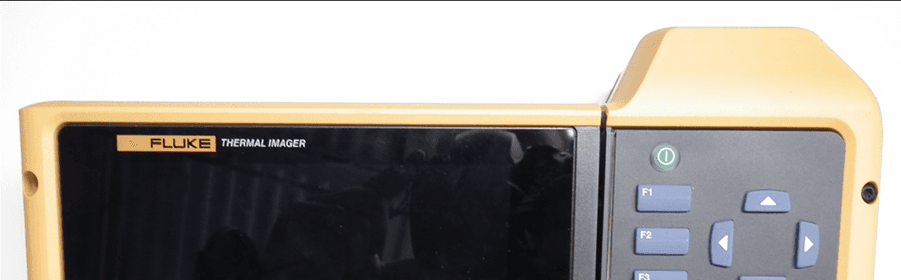
T68-FT560
May 14, 2015TiX560, TiX520
Equipment Class
DSS - Part 15 Spread Spectrum Transmitter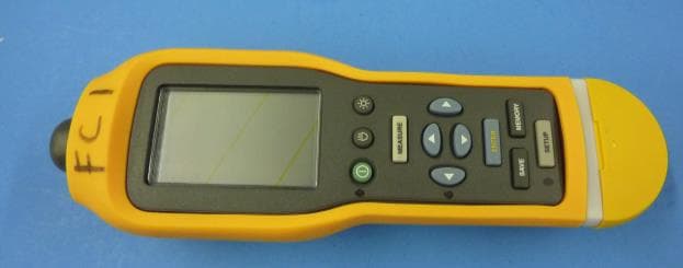
T68-805FC
May 10, 2015Vibration Meter
Equipment Class
DSS - Part 15 Spread Spectrum TransmitterT68-FBLE
Oct 27, 2013Radio Module
Equipment Class
DSS - Part 15 Spread Spectrum Transmitter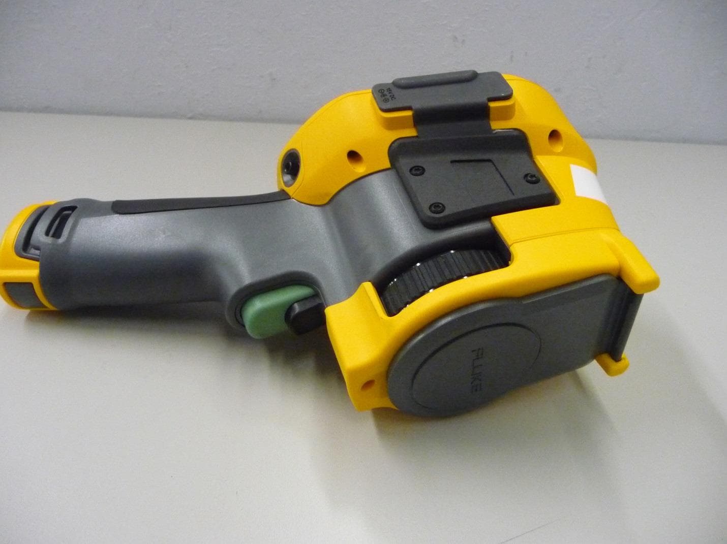
T68-FT400
Sep 29, 2013Gemini
Equipment Class
DTS - Digital Transmission System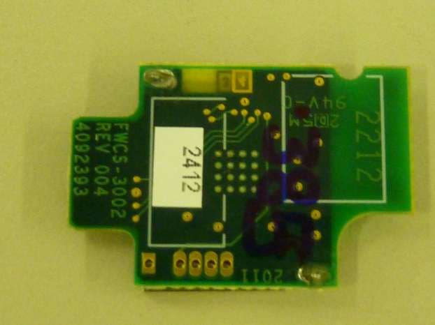
T68-FWCS
Oct 07, 2012Radio Module
Equipment Class
DTS - Digital Transmission System