T68-FT400Gemini
Fluke Electronics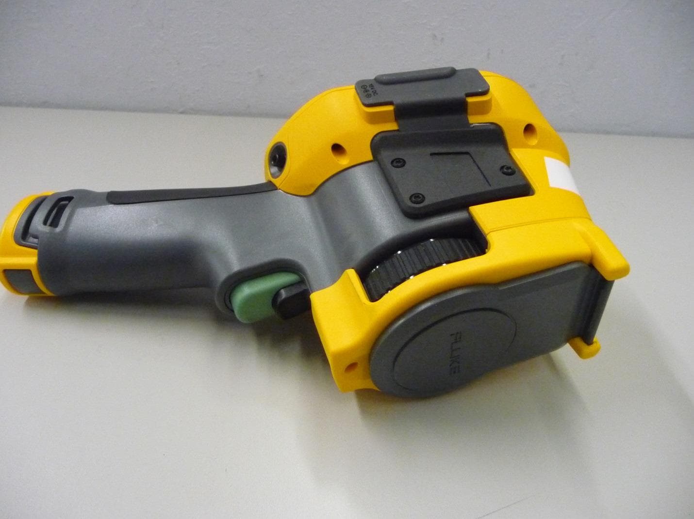
Click to zoom
Application Details
- Equipment Class
- DTS - Digital Transmission System
- Date of Grant
- Sep 29, 2013
- Application Purpose
- Original Equipment
- Date of Application
- Sep 29, 2013
- Equipment Note
- Gemini
- Frequency Range
- 2437.00000000 - 2462.00000000
- Company
- Fluke Electronics
- Country
- United States
Documents & Files
Document Text
Text extracted from the exhibit documents filed with the FCC. Open a document above to read the original.
Users Manual
4333628 August 2013 © 2013 Fluke Corporation. All rights reserved. All product names are trademarks of their respective companies. Radio Frequency Data 1 Introduction Information about radio frequency data is subject to change without notice. For up-to-date information, go to www.fluke.com. FCC/IC Information Note Changes or modifications to the wireless 2.4 GHz radio not expressly approved by Fluke Corporation could void the user’s authority to operate the equipment. This device complies with Part 15 of the FCC Rules. Operation is subject to the two conditions that follow: (1) this device can not cause interference and (2) this device must accept any interference, including interference that can cause undesired operation of the device. Class B digital device: A digital device that is marketed for operation in a residential environment notwithstanding use in commercial, business, and industrial environments. Examples of such devices include, but are not limited to, personal computers, calculators, and equivalent electronic devices that are marketed for operation by the general public. The Radio Frequency Data 2 device was tested and found to comply with the limits for a Class B digital device, pursuant to Part 15 of the FCC Rules. These limits are designed to provide reasonable protection against harmful interference in a residential installation. This equipment generates, uses, and can radiate radio frequency energy and, if not installed and used in accordance with the instructions, can cause harmful interference to radio communications. However, there is no guarantee that interference will not occur in a particular installation. If this equipment does cause harmful interference to radio or television reception, which can be determined by turning the equipment off and on, the user is encouraged to try to correct the interference by one or more of the measures that follow: • Reorient or relocate the receiving antenna. • Increase the separation between the equipment and receiver. • Consult the dealer or an experienced radio/TV technician for help. The term “IC” before the radio certification number only signifies the device meets Industry’s Canada technical specifications. Radio Frequency Data 3 Country-Specific Information Brazil Este equipamento opera em caráter secundário, isto é, não tem direito a proteção contra interferência prejudicial, mesmo de estações do mesmo tipo, e não pode causar interferência a sistemas operando em caráter primário.” Mexico La operación de este equipo está sujeta a las siguientes dos condiciones: (1) es posible que este equipo o dispositivo no cause interferencia perjudicial y (2) este equipo o dispositivo debe aceptar cualquier interferencia, incluyendo la que pueda causar su operación no deseada. S. Korea 당해 무선설비는 전파혼신 가능성이 있으므로 인명안전과 관련된 서비스는 할수 없음 Taiwan 低功率電波輻性電機管理辦法第十二條經型式認證合格之低功率射頻電機, 非經許可,公司、商號或使用者均不得擅自變更頻率、加大功率或變更原設 計之特性及功能。第十四條低功率射頻電機之使用不得影響飛航安全及干擾 合法通信;經發現有干擾現象時,應立即停用,並改善至無干擾時方得繼續 使用。前項合法通信,指依電信規定作業之無線電信。低功率射頻電機須忍 受合法通信或工業、科學及醫療用電波輻射性電機設備之干擾。 Radio Frequency Data 4 Thailand อุปกรณ์ด้านการโทรคมนาคมนี ้ เป็นไปตามข้อก ํ าหนดด้านเทคนิคNTC
Users Manual
PN 4281773 September 2013 © 2013 Fluke Corporation. All rights reserved. Specifications are subject to change without notice. All product names are trademarks of their respective companies. Ti200, Ti300, Ti400 Thermal Imagers Users Manual LIMITED WARRANTY AND LIMITATION OF LIABILITY Each Fluke product is warranted to be free from defects in material and workmanship under normal use and service. The warranty period is two years and begins on the date of shipment. Parts, product repairs, and services are warranted for 90 days. This warranty extends only to the original buyer or end-user customer of a Fluke authorized reseller, and does not apply to fuses, disposable batteries, or to any product which, in Fluke's opinion, has been misused, altered, neglected, contaminated, or damaged by accident or abnormal conditions of operation or handling. Fluke warrants that software will operate substantially in accordance with its functional specifications for 90 days and that it has been properly recorded on non-defective media. Fluke does not warrant that software will be error free or operate without interruption. Fluke authorized resellers shall extend this warranty on new and unused products to end-user customers only but have no authority to extend a greater or different warranty on behalf of Fluke. Warranty support is available only if product is purchased through a Fluke authorized sales outlet or Buyer has paid the applicable international price. Fluke reserves the right to invoice Buyer for importation costs of repair/replacement parts when product purchased in one country is submitted for repair in another country. Fluke's warranty obligation is limited, at Fluke's option, to refund of the purchase price, free of charge repair, or replacement of a defective product which is returned to a Fluke authorized service center within the warranty period. To obtain warranty service, contact your nearest Fluke authorized service center to obtain return authorization information, then send the product to that service center, with a description of the difficulty, postage and insurance prepaid (FOB Destination). Fluke assumes no risk for damage in transit. Following warranty repair, the product will be returned to Buyer, transportation prepaid (FOB Destination). If Fluke determines that failure was caused by neglect, misuse, contamination, alteration, accident, or abnormal condition of operation or handling, including overvoltage failures caused by use outside the product’s specified rating, or normal wear and tear of mechanical components, Fluke will provide an estimate of repair costs and obtain authorization before commencing the work. Following repair, the product will be returned to the Buyer transportation prepaid and the Buyer will be billed for the repair and return transportation charges (FOB Shipping Point). THIS WARRANTY IS BUYER'S SOLE AND EXCLUSIVE REMEDY AND IS IN LIEU OF ALL OTHER WARRANTIES, EXPRESS OR IMPLIED, INCLUDING BUT NOT LIMITED TO ANY IMPLIED WARRANTY OF MERCHANTABILITY OR FITNESS FOR A PARTICULAR PURPOSE. FLUKE SHALL NOT BE LIABLE FOR ANY SPECIAL, INDIRECT, INCIDENTAL, OR CONSEQUENTIAL DAMAGES OR LOSSES, INCLUDING LOSS OF DATA, ARISING FROM ANY CAUSE OR THEORY. Since some countries or states do not allow limitation of the term of an implied warranty, or exclusion or limitation of incidental or consequential damages, the limitations and exclusions of this warranty may not apply to every buyer. If any provision of this Warranty is held invalid or unenforceable by a court or other decision-maker of competent jurisdiction, such holding will not affect the validity or enforceability of any other provision. Fluke Corporation P.O. Box 9090 Everett, WA 98206-9090 U.S.A. Fluke Europe B.V. P.O. Box 1186 5602 BD Eindhoven The Netherlands 11/99 To register your product online, visit http://register.fluke.com . i Table of Contents Title Page Introduction ................................................................................ 1 How to Contact Fluke ................................................................. 2 Safety Information ...................................................................... 2 Radio Frequency Data ............................................................... 5 Accessories ................................................................................ 5 Before You Start ......................................................................... 7 Battery .................................................................................... 8 Two-Bay Battery Charger Base........................................... 8 On-Imager AC Power Socket .............................................. 9 Optional 12 V Vehicle Charger ............................................ 10 Power On and Off ................................................................... 10 Operation in Extreme Conditions ............................................... 10 Features and Controls ................................................................ 11 Primary and Secondary Triggers ................................................ 13 Focus ......................................................................................... 13 Control Buttons .......................................................................... 14 Touch Screen ............................................................................. 14 How to Use the Menus ............................................................... 15 Image Capture ........................................................................... 15 IR-PhotoNotes™..................................................................... 16 Voice Annotation (Recording) ................................................. 17 Listen to a Voice Annotation (Recording) ............................... 17 Edit Captured Infrared Image ................................................. 18 Save Captured Infrared Image ..............................................…
Text truncated - open the document above for the full version.
Block Diagram
Fluke Corporation Telephone Facsimile Email PO Box 9090 Everett WA 98206.9090 USA 425.347.6100 425.356.5108 http//www.fluke.com Date: 11 September 2013 Subject: Confidentiality Request for FCC ID: T68-FT400 Pursuant to FCC 47 CRF 0.457(d) and 0.459 and IC RSP-100, Section 10, the applicant requests that a part of the subject FCC/IC application be held confidential. Type of Confidentiality Requested Exhibit Short Term Permanent Block Diagrams Short Term Permanent Internal Photos Short Term Permanent Operation Description/Theory of Operation Short Term Permanent Tune-Up Procedure Short Term Permanent Schematics Short Term Permanent User’s Manual Fluke Corporation has spent substantial effort in developing this product and it is one of the first of its kind in industry. Having the subject information easily available to "competition" would negate the advantage they have achieved by developing this product. Not protecting the details of the design will result in financial hardship. Permanent Confidentiality: The applicant requests the exhibits listed above as permanently confidential be permanently withheld from public review due to materials that contain trade secrets and proprietary information not customarily released to the public. Short-Term Confidentiality: The applicant requests the exhibits selected above as short term confidential be withheld from public view for a period of 180 days from the date of the Grant of Equipment Authorization and prior to marketing. This is to avoid premature release of sensitive information prior to marketing or release of the product to the public. Applicant is also aware that they are responsible to notify TUV Rheinland in the event information regarding the product or the product is made available to the public. TUV Rheinland will then release the documents listed above for public disclosure pursuant to FCC Public Notice DA 04-1705. Sincerely, By: ________________________ Joseph E. Swanzy/ Prod Eval Mgr (Signature) (Print name/Title)
Cover Letter(s)
Fluke Corporation Telephone Facsimile Email PO Box 9090 Everett WA 98206.9090 USA 425.347.6100 425.356.5108 http//www.fluke.com Date: 10 September 2013 TUV Rheinland Group 762 Park Avenue Youngsville, NC 27596 To Whom It May Concern: I appoint TUV Rheinland Group to act as our agent in the preparation of this application for equipment certification. I certify that submitted documents properly describe the device or system for which equipment certification is sought. I also certify that each unit manufactured, imported or marketed, as defined in the FCC or Industry Canada’s regulations will have affixed to it a label identical to that submitted for approval with this application. For instances where our authorized agent signs the application for certification on our behalf, I acknowledge that all responsibility for complying with the terms and conditions for Certification, as specified by TUV Rheinland Group, still resides with Fluke Corporation, 6920 Seaway Blvd., Everett, WA, 98062 USA. For TCB applications, We certify that we are not subject to denial of federal benefits, that includes FCC benefits, pursuant to Section 5301 of the Anti-Drug Abuse Act of 1988, 21 U.S.C. 862. Further, no party, as defined in 47 CFR 1.2002 (b), to the application is subject to denial of federal benefits, that includes FCC benefits. Thank you, Agency Agreement Expiration Date: _____9 months beginning 10 September 2013_____ By: __________________________ Joseph E. Swanzy (Signature) (Print name) Title: Product Evaluation Manager Telephone: 425-446-5626 On behalf of: Fluke Corporation (Company Name)
Cover Letter(s)
Cover letter Fluke Thermal image device Gemini FCCID: T68-FT400; IC: 6627A-FT400 Gemini is Thermal Imager with Wi-Fi, Blue tooth and Zigbee radios and is used as Portable measuring device. The Thermal Imagers have three Models: Ti200, Ti300, and Ti400. The model differences are with Infrared Resolution, Temperature Measurements Ranges, and Thermal Sensitivity. The models use the same hardware. Software settings are used to configure the models. Ti400 with highest camera resolution was used for testing. Gemini has Zigbee radio which not evaluated before. The main focus is testing and qualifying Zigbee radio. Test report # 31362328.001 dated Sep 13, 2013 covers Zibee testing. The device has passed required regulations. Gemini also uses LS Research approved module PN: 450-0064R with Single modular approval with FCC ID: TFB-TIWI1-01 and IC: 5969-TIWI101. Fluke Corporation uses the above module with following changes 1) Using lower gain antenna ceramic chip max gain of 1.5dBi instead of 2) Added switch uPG2214TB GaAs, Integrated Circuit for L, S-Band SPDT Switch manufactured by California Eastern Labs. This switch accommodates use of the same antenna by Zigbee radio as well as Wi-Fi and Bluetooth radio module. Blue tooth and WIFI radios can operate simultaneously. Zigbee never operates simultaneously with Blue tooth and WIFI 1) Zigbee radio was evaluated for all tests required for FCC 15.247. 2) No changes were made Blue tooth radio. Preliminary tests indicated no reduction power was required. Spurious emissions were lower than module approval. Test results of module approval are applicable 3) For Wi-Fi radio power was reduced. Power levels are recorded in the test report. Limited evaluation of Wi-Fi radio was performed. Band edges, power levels and Radiated spurious emissions shall be re-evaluated. All the conducted measurements of Wi-Fi are still applicable. EUT shall be evaluated for simultaneous operation of Wi-Fi and Blue tooth radios. All conducted tests results of module are applicable. Test results are presented in Test report # 31362328.001 dated Sep 13, 2013 (Suresh Kondapalli) Test Engineer
Cover Letter(s)
Fluke Corporation Telephone Facsimile Email PO Box 9090 Everett WA 98206.9090 USA 425.347.6100 425.356.5108 http//www.fluke.com Date: 11 September 2013 Subject: Confidentiality Request for FCC ID: T68-FT400 Pursuant to FCC 47 CRF 0.457(d) and 0.459 and IC RSP-100, Section 10, the applicant requests that a part of the subject FCC/IC application be held confidential. Type of Confidentiality Requested Exhibit Short Term Permanent Block Diagrams Short Term Permanent Internal Photos Short Term Permanent Operation Description/Theory of Operation Short Term Permanent Tune-Up Procedure Short Term Permanent Schematics Short Term Permanent User’s Manual Fluke Corporation has spent substantial effort in developing this product and it is one of the first of its kind in industry. Having the subject information easily available to "competition" would negate the advantage they have achieved by developing this product. Not protecting the details of the design will result in financial hardship. Permanent Confidentiality: The applicant requests the exhibits listed above as permanently confidential be permanently withheld from public review due to materials that contain trade secrets and proprietary information not customarily released to the public. Short-Term Confidentiality: The applicant requests the exhibits selected above as short term confidential be withheld from public view for a period of 180 days from the date of the Grant of Equipment Authorization and prior to marketing. This is to avoid premature release of sensitive information prior to marketing or release of the product to the public. Applicant is also aware that they are responsible to notify TUV Rheinland in the event information regarding the product or the product is made available to the public. TUV Rheinland will then release the documents listed above for public disclosure pursuant to FCC Public Notice DA 04-1705. Sincerely, By: ________________________ Joseph E. Swanzy/ Prod Eval Mgr (Signature) (Print name/Title)
Cover Letter(s)
Fluke Corporation Telephone Facsimile Email PO Box 9090 Everett WA 98206.9090 USA 425.347.6100 425.356.5108 http//www.fluke.com To whom it may concern Authority to Act as Agent On my behalf, I appoint Joe Swanzy with Fluke Corporation, to act as my authorized agent in the preparation of all radio application approval forms for Fluke Corporation for the following models: Fluke Ti200, Ti300, and Ti400 For instances where my authorized agent signs the documentation on my behalf, I acknowledge that all responsibility for complying with the terms and conditions for equipment type approval still resides with Fluke Corporation 6920 Seaway Blvd. Everett, WA, 98062 USA Dated this 13 Day of September 20 13 By: Thomas M Smith, PE Signature Printed Title: Product Evaluation, MS 143F On behalf of : Fluke Corporation Telephone: 1(425)446-5027
External Photos
External Photos FCC ID: T68-FT400 IC: 6627A-FT400 Front View Back side View Top View Right side access points Left side access points Battery
ID Label/Location Info
DECAL, DUST COVER 89536dustcover_back_gemini.ai JEFF ELROD FLUKE-TI200-8010 22 4330472 NOTES: 1. ARTWORK MUST BE REGISTERED TO WITHIN 0.01 IN 2. NOTE: DECAL TO BE GREY #8 Munsell 0.8PB 2.81/0.2 UNLESS OTHERWISE NOTED ARTWORK TO BE: ARTWORKREFERENCE FLUKE CORPORATION EVERETT, WA USA www. uke.com FCC ID: T68-FT400 IC: 6627A-FT400 CONTAINS FCC ID: TFB-TIWI1-01 IC: 5969A-TIWI101 FLUKE CORPORATION EVERETT, WA USA www. uke.com FCC ID: T68-FT400 IC: 6627A-FT400 CONTAINS FCC ID: TFB-TIWI1-01 IC: 5969A-TIWI101
ID Label/Location Info
Label Location FCC ID: T68-FT400 IC: 6627A-FT400
Internal Photos
Internal Photos FCC ID: T68-FT400 IC: 6627A-FT400 Front cover Removed PCB with radio Components Marked Backside of PCB PCB with radio portion expanded
Operational Description
Fluke Corporation Telephone Facsimile Email PO Box 9090 Everett WA 98206.9090 USA 425.347.6100 425.356.5108 http//www.fluke.com Product Overview The Ti400 Series of Thermal Imagers are handheld imaging products that can detect infrared radiation (IR). The primary use is for preventive maintenance and diagnosing problems in industrial environments. These products are not intended for sale to consumers. The series has three versions labeled Ti400, Ti300, and Ti200. The versions use the same common IR camera body assembly (Fluke part number 4340874). This IR camera body is shown in Figure 1. Other than the model numbers, the electronics, mechanical components, layout, bill of materials, assembly procedures, and test processes are the exactly same for the three versions. The versions are configured through software flags in the flash RAM at the end of the production line to match the customer’s order. The differences between the versions are the following: IR Resolution: Ti400 provides 320 x 240 IR pixel resolution, Ti300 provides 240 x 180 IR pixel resolution, and Ti200 provides 200 x 150 IR pixel resolution. The same 320x240 IR Sensor is used in all three versions. Embedded software within the IR Camera decimates the 320x240 IR image to achieve 200x150 and 240x180 resolutions. Thermal Sensitivity: The thermal sensitivity is the minimal temperature difference that the thermal camera can detect. Ti400 and Ti300 can detect down to 0.05 °C temperature difference. Ti200 can detect down to 0.075 °C temperature difference. The native thermal sensitivity of the IR Camera is 0.050 °C. Embedded software within the IR Camera reduces the thermal sensitivity for the Ti200 version. Fluke Corporation Telephone Facsimile Email PO Box 9090 Everett WA 98206.9090 USA 425.347.6100 425.356.5108 http//www.fluke.com The IR Camera body of the thermal imager contains the following radios: • 802.11b/g (WLAN) • Bluetooth • 802.15.4 (Communicates with other Fluke-made devices having a Fluke proprietary 802.15.4 type radio) The radios are contained on the main processing circuit board (Fluke PN 4106556) . Radio Theory of Operation The Fluke Ti200/300/400 Thermal imagers support three radio standards: 802.15.4, 802.11 b/g and Bluetooth, all operating on the 2540MHz ISM band. The three transceivers share an antenna and matching network. The system processor controlled RF switch selects which radios are connected to the antenna. The radios operate in one of two modes: 1. 802.15.4 enabled, WiFi and Bluetooth both disabled. 2. WiFi and Bluetooth both enabled, 802.15.4 disabled. The antenna used is a 2.45GHz Ceramic Chip Antenna with a peak gain of 1.5dBi. The thermal imager, including the radios, will automatically cease operation and thus communication once battery capacity reaches a specified minimum threshold. 802.15.4: A Texas Instruments CC2530F256 IC, wireless transceiver radio is used to communicate with other compatible wireless products. The transceiver is short range and low power, with a physical layer compliant to IEEE 802.15.4 . The packet structure incorporates a point to point proprietary method. The radio IC has an RF core that controls the internal transceiver (RF transmit and receive) segments. In addition, it provides an interface between an internal 8051 MCU and the radio circuits. This makes it possible to issue commands, read status, and automate and sequence radio events. The radio IC transceivers include a low noise amplifier, software controlled power amplifier, onboard RF transmit/receive, phase lock loop with internal voltage controlled oscillator, in-IC power supply regulation, and full spread-spectrum encoding and decoding. The radio IC is programmable in 1-MHz steps with 5.0 MHz channel spacing per the 802.15.4 standard. The radio IC also includes a packet-filtering and address-recognition capability. All radio settings and protocols are programmed at manufacturing and cannot be modified by a user. A SPI port is provided to communicate to an external CPU for receive (RX) and transmit (TX) data transfer and control. The radio must first be initialized by the internal MCU before the transceivers are able to communicate with other products. The range of these transceivers is specified at 30ft but under ideal conditions my reach 100 ft. There are no additional peripheral devices supported or required at this time. WLAN and Bluetooth: An LS Research TiWI-BLE integrated radio module is used to provide both WLAN 802.11b/g and Bluetooth 2.1+BLE support. The TiWi module is based on the Texas Instruments WL1271L transceiver, and also includes power regulators, control circuitry, RF switch, and output power amplifiers for both WLAN and Bluetooth operation. Fluke Corporation Telephone Facsimile Email PO Box 9090 Everett WA 98206.9090 USA 425.347.6100 425.356.5108 http//www.fluke.com For WLAN operation an SDIO port is provided to communicate to the system CPU for receive (RX) and transmit (TX) data transfer and control. For Bluetooth operation an I2S port is provided for data transfer and control. An additional serial UART, interrupt (IRQ), and module enable signals are provided for module control. These are also connected to the system processor. All WLAN and Bluetooth radio settings and protocols are programmed at manufacturing and cannot be modified by a user, with the exception of WLAN channel selection. Block Diagram Fluke Ti200/300/400 Family of radio Instruments Matching Network System Microprocessor TI CC2530F 802.15.4 Transceiver SPI LS Research TiWi-BLE WiFi/Bluetooth Module SDIO I2S Switch Control RF Switch CEL UPG2214TB Antenna Johanson Technology 2540AT18D0100 32MHz 32.768 KHz
RF Exposure Info
Report Number: 31362328.001 Appendix A Page 1 of 7 EUT: Gemini Models: Ti400, Ti300 and Ti200 EMC / Rev 9/13/2013 FCCID: T68-FT400; IC: 6627A-FT400 RF Exposure Exhibit EUT Name: Gemini Model Nos.: Ti400, Ti300 and Ti200 CFR Part 1.1310 and RSS 102 Prepared for: Fluke Corporation. 6920 Seaway Blvd Everett, WA 98203 USA Tel: (425) 446-5626 Prepared by: TUV Rheinland of North America, Inc. 1279 Quarry Lane Pleasanton, CA 94566 Tel: (925) 249-9123 Fax: (925) 249-9124 http://www.tuv.com/ Report/Issue Date: September 13, 2013 Report Number: 31362328.001 Appendix A TUV Rheinland RF Exposure Limit 1279 Quarry Lane, Ste. A, Pleasanton, CA 95466 Tel: (925) 249-9123, Fax: (925) 249-9124 Report Number: 31362328.001 Appendix A Page 2 of 7 EUT: Gemini Models: Ti400, Ti300 and Ti200 EMC / Rev 9/13/2013 FCCID: T68-FT400; IC: 6627A-FT400 Contents RF Exposure Exhibit ................................................................................................................. 1 1 Test Methodology .................................................................................................................... 3 1.1 RF Exposure Limit ..................................................................................................................... 3 1.2 EUT Operating Condition .......................................................................................................... 4 1.3 SAR requirements and justification .......................................................................................... 4 1.3.1 Antenna Gain ........................................................................................................................................... 4 1.3.2 Portable configuration and hand position ................................................................................................ 4 1.4 MPE calculation .......................................................................................................................... 6 1.4.1 Portable Configuration ............................................................................................................................. 6 1.4.2 Sample Calculation .................................................................................................................................. 7 TUV Rheinland RF Exposure Limit 1279 Quarry Lane, Ste. A, Pleasanton, CA 95466 Tel: (925) 249-9123, Fax: (925) 249-9124 Report Number: 31362328.001 Appendix A Page 3 of 7 EUT: Gemini Models: Ti400, Ti300 and Ti200 EMC / Rev 9/13/2013 FCCID: T68-FT400; IC: 6627A-FT400 1 Test Methodology In this document, we evaluate the RF Exposure to human body due the intentional transmission from the transmitter (EUT). The limit for Maximum Permissible Exposure (MPE) specified in FCC 1.1310 is followed. Through the Friis transmission formula and the maximum gain of the antenna, we can calculate the distance, away from the product, where the limit of MPE is reached. Although the Friis transmission formula is a far field assumption, the calculated result of that is an over- prediction for near field power density. We will take that as the worst case to specify the safety range. 1.1 RF Exposure Limit According to FCC 1.1310 table 1: The criteria listed in the following table shall be used to evaluate the environmental impact of human exposure to radio-frequency (RF) radiation as specified in 1.1307(b) LIMITS FOR MAXIMUM PERMISSIBLE EXPOSURE (MPE) Frequency Range (MHz) Electric Field Strength (V/m) Magnetic Field Strength (A/m) Power Density (mW/cm 2) Average Time (minutes) (A)Limits For Occupational / Control Exposures 0.3-1.34 614 1.63 *(100) 6 1.34-30 1842/f 4.89/f *(900/f²) 6 30-300 61.4 0.163 1.0 6 30-1500 ... ... F/300 6 1500-100000 ... ... 1.0 6 (B)Limits For General Population / Uncontrolled Exposure 0.3-1.34 614 1.63 *(100) 30 1.34-30 824/f 2.19/f *(180/f²) 30 30-300 27.5 0.073 0.2 30 30-1500 ... ... F(MHz)/1500MHz 30 1500-100000 ... ... 1.0 30 F = Frequency in MHz *=Plane wave equivalent density TUV Rheinland EUT Operating Condition 1279 Quarry Lane, Ste. A, Pleasanton, CA 95466 Tel: (925) 249-9123, Fax: (925) 249-9124 Report Number: 31362328.001 Appendix A Page 4 of 7 EUT: Gemini Models: Ti400, Ti300 and Ti200 EMC / Rev 9/13/2013 FCCID: T68-FT400; IC: 6627A-FT400 1.2 EUT Operating Condition The Ti400 Series of Thermal Imagers are handheld imaging products that can detect infrared radiation (IR). The primary use is for preventive maintenance and diagnosing problems in industrial environments. These products are not intended for sale to consumers. The series has three versions labeled Ti400, Ti300, and Ti200. The versions use the same common IR camera body assembly (Fluke part number 4340874). This IR camera body IR Camera body of the thermal imager contains the following radios: • 802.11b/g (WLAN) • Bluetooth • 802.15.4 (Communicates with other Fluke-made devices having a Fluke proprietary 802.15.4 type radio) The three transceivers share an antenna and matching network. The system processor controlled RF switch selects which radios are connected to the antenna. The radios operate in one of two modes: 1. 802.15.4 enabled, WiFi and Bluetooth both disabled. 2. WiFi and Bluetooth both enabled, 802.15.4 disabled The antenna used is a 2.45GHz Ceramic Chip Antenna with a peak gain of 1.5dBi. The thermal imager, including the radios, will automatically cease operation and thus communication once battery capacity reaches a specified minimum threshold. RF exposure for co-location and simultaneous transmission is evaluated in this report. 1.3 SAR requirements and justification 1.3.1 Antenna Gain The antenna used is a 2.45GHz Ceramic Chip Antenna with a peak gain of 1.5dBi. 1.3.2 Portable configuration and hand position Tr…
Text truncated - open the document above for the full version.
Contact Information
Applicant
James E Lenker(Test Engineer)
Test Firm
TUV Rheinland of North America Inc.David Spencer
Technical Specifications
| # | Rule Parts | Frequency Range | Power Output |
|---|---|---|---|
| 4 | 15C | 2.44 GHz - 2.46 GHz | 35.50 mW |
Other Applications from Fluke Electronics
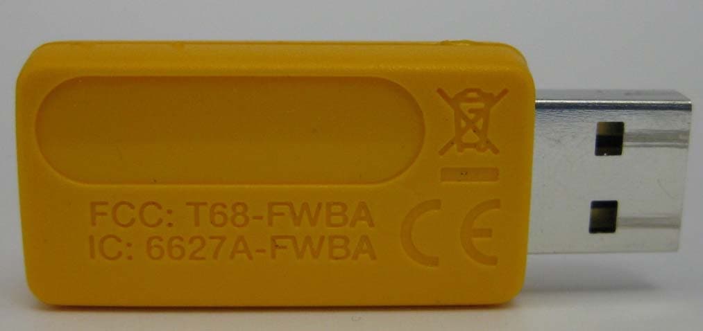
T68-FWBA
Oct 27, 2015USB1 FC WiFi-BLE Adapter
Equipment Class
DTS - Digital Transmission System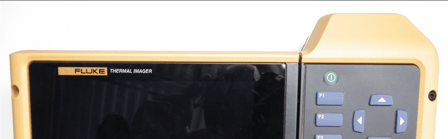
T68-FT560
May 14, 2015TiX560, TiX520
Equipment Class
DSS - Part 15 Spread Spectrum Transmitter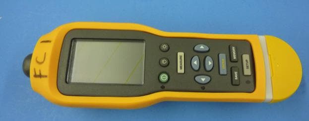
T68-805FC
May 10, 2015Vibration Meter
Equipment Class
DSS - Part 15 Spread Spectrum TransmitterT68-FBLE
Oct 27, 2013Radio Module
Equipment Class
DSS - Part 15 Spread Spectrum Transmitter
T68-FWCS
Oct 07, 2012Radio Module
Equipment Class
DTS - Digital Transmission System