T68-FT560TiX560, TiX520
Fluke Electronics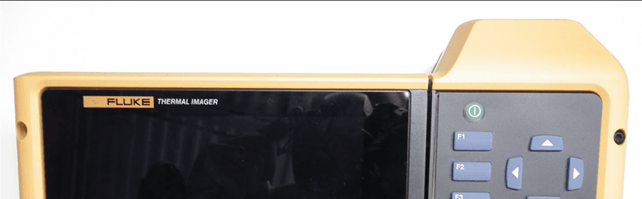
Click to zoom
Application Details
- Equipment Class
- DSS - Part 15 Spread Spectrum Transmitter
- Date of Grant
- May 14, 2015
- Application Purpose
- Original Equipment
- Date of Application
- May 14, 2015
- Equipment Note
- TiX560, TiX520
- Frequency Range
- 2402.00000000 - 2480.00000000
- Company
- Fluke Electronics
- Country
- United States
Documents & Files
Document Text
Text extracted from the exhibit documents filed with the FCC. Open a document above to read the original.
Users Manual
February 2015 © 2015 Fluke Corporation. All rights reserved. Specifications are subject to change without notice. All product names are trademarks of their respective companies. TiX520, TiX560 Expert Series Thermal Imager Users Manual LIMITED WARRANTY AND LIMITATION OF LIABILITY Each Fluke product is warranted to be free from defects in ma terial and workmanship under normal use and service. The warranty period is two years and begins on the date of shipment. Parts, product repairs, and services are warranted for 90 days. This warranty extends only to the original buyer or e nd-user customer of a Fluke authorized reseller, and does not apply to fuses, disposable batteries, or to any product which, in Fluke's opinion, has been misused, altered, neglecte d, contaminated, or damaged by accident or abnormal conditions of operation or handling. Fluke warrants that software will operate substantially in accordance with its functional specifications for 90 days and that it has been properly recorded on non-defective media. Fluke does not warrant that software will be error free or operate without interruption. Fluke authorized resellers shall extend this warranty on new and unused products to end-user customers only but have no authori ty to extend a greater or different warranty on behalf of Fluke. Warranty support is available only if product is purchased through a Fluke authorized sales outlet or Buyer ha s paid the applicable international price. Fluke reserves the right to invoice Buyer for importation costs of r epair/replacement parts when product purchased in one country is submitted for repair in another country. Fluke's warranty obligation is limited, at Fluke's option, to ref und of the purchase price, free of charge repair, or replaceme nt of a defective product which is returned to a Fluke authorized service center within the warranty period. To obtain warranty service, contact your nearest Fluke authorized service center to obtain return authorization information, th en send the product to that service center, with a description of the difficulty, postage and insurance prepaid (FOB Destination). Fluke assumes no risk for damage in transit. Fo llowing warranty repair, the product will be returned to Buyer, transportation prepaid (FOB Destination). If Fluke determines that failure was caused by neglect, misuse, contamination, alteration, accident, or abnormal condition of operation or handling, including overvoltage failures caused by use outside the product’s specified rating, or normal wear and tear of mechanical components, Fluke will provide an estimate of repair costs and obtain authorization before comm encing the work. Following repair, the product will be returned to the Buyer transportation prepaid and the Buyer will be billed for the repair and return transportation charges (FOB Shipping Point). THIS WARRANTY IS BUYER'S SOLE AND EXCLUSIVE REMEDY AND IS IN LIEU OF ALL OTHER WARRANTIES, EXPRESS OR IMPLIED, INCLUDING BUT NO T LIMITED TO ANY IMPLIED WARRANTY OF MERCHANTABILITY OR FITNESS FOR A PARTICULAR PURPOSE. FLUKE SHALL NOT BE LIABLE FOR ANY SPECIAL, INDIREC T, INCIDENTAL, OR CONSEQUENTIAL DAMAGES OR LOSSES, INCLUDING LOSS OF DATA, ARISING FROM ANY CAUSE OR THEORY. Since some countries or states do not allow limitation of the term of an implied warranty, or exclusion or limitation of incide ntal or consequential damages, the limitations and exclusions of this warranty may not apply to every buyer. If any provision of this Warranty is held invalid or unenforceable by a court or other decision-maker of competent jurisdiction, such holding will not affect the va lidity or enforceability of any other provision. Fluke Corporation P.O. Box 9090 Everett, WA 98206-9090 U.S.A. Fluke Europe B.V. P.O. Box 1186 5602 BD Eindhoven The Netherlands 11/99 To register your product online, visit http://register.fluke.com . i Table of Contents Title Page Introduc tion .................................................................................................................. .. 1 How to Contact Fluke .................................................................................................... 2 Safety Information .......................................................................................................... 2 Operation in Extreme Conditions .............................................................................. 3 Radio Frequency Data .............................................................................................. 3 Accessories ................................................................................................................... 5 Before You Start ............................................................................................................ 6 Battery ...................................................................................................................... 7 Two-Bay Battery Charger Base ............................................................................ 7 On-Imager AC Powe r Socket ............................................................................... 7 Optional 12 V Vehicl e Charger ............................................................................. 8 Features and Controls .............................................................................................. 10 Power On and Off ..................................................................................................... 11 Focus ........................................................................................................................ 11 Image Capture Button ............................................................................................... 12 Control Buttons ......................................................................................................... 12 Touch Screen............................................................................................................ 15 How …
Text truncated - open the document above for the full version.
Users Manual
PN 4333628 September 2013, Rev.3, 4/15 © 2013-2015 Fluke Corporation. All rights reserved. All product names are trademarks of their respective companies. Radio Frequency Data for Class A 1 Introduction Information about radio frequency data is subject to change without notice. For up-to-date information, go to www.fluke.com. FCC/IC Information Class A digital device: This equipment has been tested and found to comply with the limits for a Class A digital device, pursuant to Part 15 of the FCC Rules. Operation is subject to the two conditions that follow: (1) this device can not cause interference and (2) this device must accept any interference, including interference that can cause undesired operation of the device. These limits are designed to provide reasonable protection against harmful interference when the equipment is operated in a commercial environment. This equipment generates, uses, and can radiate radio frequency energy, and if it is not installed and used in accordance with the instruction manual, it may cause harmful interference to radio communications. Operation of this equipment in a residential area is likely to cause harmful interference, in which case the user will be required to correct the interference at his own expense. Radio Frequency Data Class A 2 The term “IC” before the radio certification number only signifies the device meets Industry’s Canada technical specifications. Note Changes or modifications to the wireless 2.4 GHz radio not expressly approved by Fluke Corporation could void the user’s authority to operate the equipment. This device complies with Industry Canada license-exempt RSS standard(s). Operation is subject to the following two conditions: (1) this device may not cause interference, and (2) this device must accept any interference, including interference that may cause undesired operation of the device. Le présent appareil est conforme aux CNR d'Industrie Canada applicables aux appareils radio exempts de licence. L'exploitation est autorisée aux deux conditions suivantes : (1) l'appareil ne doit pas produire de brouillage, et (2) l'utilisateur de l'appareil doit accepter tout brouillage radioélectrique subi, même si le brouillage est susceptible d'en compromettre le fonctionnement. The radio transmitter has been approved by Industry Canada to operate only with the antenna supplied. Use of any other antenna is strictly prohibited for use with this product. L'émetteur radio a été approuvé par Industrie Canada pour fonctionner uniquement avec l'antenne fournie. L'utilisation de toute autre antenne est strictement interdit d'utiliser ce produit. Radio Frequency Data Class A 3 MPE/SAR/RF Exposure Information MPE / SAR / RF Information sur l'Exposition This device was verified for RF exposure and found to comply with FCC OET-65 RF Exposure and RSS-102 requirements. This Product meets the SAR exemption based on its output power. Ce produit a été vérifiée pour l'exposition de puissance radio et jugé conforme aux normes FCC OET-65 et RSS-102 exigences. Sur la base de la puissance de sortie de la radio, ce produit répond aux taux d'absorption spécifique exemption. Country-Specific Information Brazil Este equipamento opera em caráter secundário, isto é, não tem direito a proteção contra interferência prejudicial, mesmo de estações do mesmo tipo, e não pode causar interferência a sistemas operando em caráter primário.” Mexico La operación de este equipo está sujeta a las siguientes dos condiciones: (1) es posible que este equipo o dispositivo no cause interferencia perjudicial y (2) este equipo o dispositivo debe aceptar cualquier interferencia, incluyendo la que pueda causar su operación no deseada. Radio Frequency Data Class A 4 S. Korea 당해 무선설비는 전파혼신 가능성이 있으므로 인명안전과 관련된 서비스는 할수 없음 Taiwan 低功率電波輻性電機管理辦法第十二條經型式認證合格之低功率射頻電機, 非經許可,公司、商號或使用者均不得擅自變更頻率、加大功率或變更原設 計之特性及功能。第十四條低功率射頻電機之使用不得影響飛航安全及干擾 合法通信;經發現有干擾現象時,應立即停用,並改善至無干擾時方得繼續 使用。前項合法通信,指依電信規定作業之無線電信。低功率射頻電機須忍 受合法通信或工業、科學及醫療用電波輻射性電機設備之干擾。 警告使用者:這是甲類的資訊產品,在居住的環境中使用時,可能會造成射 頻干擾,在這種情況下,使用者會被要求採取某些適當的對策。 Thailand อุปกรณ์ด้านการโทรคมนาคมนี ้ เป็นไปตามข้อก ํ าหนดด้านเทคนิค NTC
Cover Letter(s)
Request for Confidentiality Date: April 9, 2015 Confidentiality Request for: Fluke TiX560 and TiX520 Thermal Imagers FCC ID: T68-FT560 IC ID: 6627A-FT560 To Whom It May Concern, Pursuant to FCC 47 CRF 0.457(d) and 0.459 and IC RSP-100, Section 6.4, the applicant requests that a part of the subject FCC and/or IC application be held confidential. The applicant requests the exhibits listed below be permanently withheld from public review due to materials that contain trade secrets and proprietary information not customarily released to the public. TiX560 TiX520 Technical Description Block Diagram Schematics Applicant has spent substantial effort in developing this product and it is one of the first of its kind in industry. Having the subject information easily available to "competition" would negate the advantage they have achieved by developing this product. Not protecting the details of the design will result in financial hardship. Sincerely, (Signature) Name: James Lenker Title: Product Compliance Engineer Phone: 425 446 5929 Email: [email protected]
External Photos
Fluke Corporation Telephone Facsimile Email PO Box 9090 Everett WA 98206.9090 USA 425.347.6100 425.356.5108 http//www.fluke.com Figure 1 TIX560 Series Camera (Front) Fluke Corporation Telephone Facsimile Email PO Box 9090 Everett WA 98206.9090 USA 425.347.6100 425.356.5108 http//www.fluke.com Figure 2 TIX560 Series Camera (Back) Fluke Corporation Telephone Facsimile Email PO Box 9090 Everett WA 98206.9090 USA 425.347.6100 425.356.5108 http//www.fluke.com Figure 3 TIX560 Series Camera Fluke Corporation Telephone Facsimile Email PO Box 9090 Everett WA 98206.9090 USA 425.347.6100 425.356.5108 http//www.fluke.com Figure 4 TIX560 Series Camera Figure 5 Model Label Figure 6 Radio Certification Label Fluke Corporation Telephone Facsimile Email PO Box 9090 Everett WA 98206.9090 USA 425.347.6100 425.356.5108 http//www.fluke.com Figure 7 Compliance Label Figure 8 SN Label Figure 9 Manufacturer Label Figure 10 Laser Warning Label
ID Label/Location Info
Fluke Corporation Telephone Facsimile Email PO Box 9090 Everett WA 98206.9090 USA 425.347.6100 425.356.5108 http//www.fluke.com Figure 1 TIX560 Series Camera Figure 2 Model Label Fluke Corporation Telephone Facsimile Email PO Box 9090 Everett WA 98206.9090 USA 425.347.6100 425.356.5108 http//www.fluke.com Figure 3 Radio Certification Label
Internal Photos
INTERNAL PHOTOS Company Name Fluke Electronics Corporation Model # TiX560 and TiX520 FCC ID # T68‐FT560 IC # 6627A‐FT560 Page 1 of 4 Figure 1 TIX560 Series Main Processing Circuit Board (Top Side) INTERNAL PHOTOS Company Name Fluke Electronics Corporation Model # TiX560 and TiX520 FCC ID # T68‐FT560 IC # 6627A‐FT560 Page 2 of 4 Figure 2 TIX560 Series Main Processing Circuit Board (Bottom Side) INTERNAL PHOTOS Company Name Fluke Electronics Corporation Model # TiX560 and TiX520 FCC ID # T68‐FT560 IC # 6627A‐FT560 Page 3 of 4 Figure 3 TIX560 Series Main Processing Circuit Board (Bottom Side with EMC Enclosure) INTERNAL PHOTOS Company Name Fluke Electronics Corporation Model # TiX560 and TiX520 FCC ID # T68‐FT560 IC # 6627A‐FT560 Page 4 of 4 Figure 4 TIX560 Series Main Processing Circuit Board (Top Side with EMC Shield)
RF Exposure Info
W66 N220 Commerce Court ● Cedarburg, WI 53012 Phone: 262.375.4400 ● Fax: 262.375.4248 www.lsr.com SAR Test Exclusion Exhibit For: Fluke TiX560/TiX520 Thermal Imager Prepared by: Khairul Aidi Zainal, Senior EMC Engineer 3/4/2015 W66 N220 Commerce Court ● Cedarburg, WI 53012 Phone: 262.375.4400 ● Fax: 262.375.4248 www.lsr.com Contents Product Description: ..................................................................................................................................... 3 Associated Antenna(s): ................................................................................................................................. 4 Statement of compliance: ............................................................................................................................. 4 Separation Distance: ..................................................................................................................................... 5 SAR Test Exclusion Threshold: ...................................................................................................................... 6 Data and calculation: .................................................................................................................................... 7 W66 N220 Commerce Court ● Cedarburg, WI 53012 Phone: 262.375.4400 ● Fax: 262.375.4248 www.lsr.com Product Description: The thermal Imager is a WLAN and Bluetooth enabled handheld imaging product that can detect infrared radiation (IR). The primary use is for preventive maintenance and diagnosing problems in industrial environments. These products are not intended for sale to consumers. The series has two versions labeled TiX520 and TiX560. The versions use the same common IR camera body assembly (Fluke part number 4596742). Other than the model numbers, the electronics, mechanical components, layout, bill of materials, assembly procedures, and test processes are the exactly same for the three versions. The versions are configured through software flags in the flash memory at the end of the production line to match the customer’s order. The differences between the versions are the following: Thermal Sensitivity: The thermal sensitivity is the minimal temperature difference that the thermal camera can detect. TiX520 can detect down to 0.05 °C temperature difference. TiX560 can detect down to 0.045 °C temperature difference. The native thermal sensitivity of the IR Camera is 0.045 °C. Embedded software within the IR Camera reduces the thermal sensitivity for the Ti200 version. Temperature Measurement rage: The TiX520 and TiX560 are Calibrated to -10°C. The TiX520’s measurement range is - 20 to 850°C and the TiX560’s measurement range is -20 to 1200°C W66 N220 Commerce Court ● Cedarburg, WI 53012 Phone: 262.375.4400 ● Fax: 262.375.4248 www.lsr.com Associated Antenna(s): The antenna associated with the EUT is a Johanson Technology high frequency ceramic chip antenna, part number 2450AT18D0100. The chip antenna has a peak gain of 1.5dBi. Statement of compliance: The Fluke TiX560/TiX520 was evaluated against the SAR test exclusion threshold listed in KDB 447498 D01 General RF Exposure Guidance v05r02, section 4.3 (1). The EUT was found to be compliant with the SAR exclusion threshold for 100MHz to 6000MHz. Evaluation was performed using a distance that is 0.375 inches or 9.525 mm. W66 N220 Commerce Court ● Cedarburg, WI 53012 Phone: 262.375.4400 ● Fax: 262.375.4248 www.lsr.com Separation Distance: The TiX560/TiX520 thermal imager is a portable imager that will be handheld and may be used with a neck strap. The radiating element is on the front of the unit as shown below: W66 N220 Commerce Court ● Cedarburg, WI 53012 Phone: 262.375.4400 ● Fax: 262.375.4248 www.lsr.com The distance used for calculation is 0.375 inches (9.525mm) as it is shown to be the closest distance to the body when using a neck strap (Refer to assembly drawing above). SAR Test Exclusion Threshold: Extremities SAR test exclusion threshold for 100MHz to 6GHz at minimum separation distance of ≤ 50mm. 1-g SAR test exclusion threshold equation: [(maximum power of channel including tune-up tolerance) / (minimum separation distance)] * [√f (GHz) ] ≤ 3.0 W66 N220 Commerce Court ● Cedarburg, WI 53012 Phone: 262.375.4400 ● Fax: 262.375.4248 www.lsr.com Data and calculation: Maximum Conducted Output Power: A. DTS 111.00.011.030.019.0 610.70.010.730.019.3 1110.70.010.730.019.3 111.90.112.030.018.0 611.30.111.430.018.6 1111.60.111.730.018.3 111.80.111.930.018.1 611.30.111.430.018.6 1111.50.111.630.018.4 111.50.111.630.018.4 610.90.111.030.019.0 1111.10.111.230.018.8 111.90.712.630.017.4 611.90.712.630.017.4 1112.10.712.830.017.2 18.70.79.430.020.6 68.70.79.430.020.6 118.90.79.630.020.4 Data Rate (MBPS) Channel Maxi mum Conducted (average) Power (dBm) Power Limit (dBm) Power margin (dB) Duty Cycl e correcti on for average meas urement (dB) Corrected Maxi mum Conducted Power (dBm) 1 (DBPSK) 6 (BPSK) MCS0 (BPSK) 11 (8QPSK) 54 (64QAM) MCS7 (64QAM) b g n b g n 802.11 Standard W66 N220 Commerce Court ● Cedarburg, WI 53012 Phone: 262.375.4400 ● Fax: 262.375.4248 www.lsr.com B. FHSS Frequency (MHz) Conducted Output Power (dBm) Conducted Power Limit (dBm) Conducted Power Margin (dB) 24021.430.028.6 24400.930.029.1 2480-0.330.030.3 124021.321.019.7 3924400.621.020.4 7924800.621.020.4 124024.021.017.0 3924403.721.017.3 7924803.621.017.4 124024.621.016.4 3924404.421.016.6 7924804.421.016.6 Output power limit (dBm) Margin (dB) GFSK EDR2 EDR3 Packet TypeChannel Frequency (MHz) Output Power (dBm) W66 N220 Commerce Court ● Cedarburg, WI 53012 Phone: 262.375.4400 ● Fax: 262.375.4248 www.lsr.com Screen Capture of maximum output power Note: A duty cycle correction (0.7dB) was added to the output power shown in the plot above to account for the signal having less than 97% duty cycle. W66 N220 Commerce Court ● Cedarburg, WI 53012 Phone: 262.375.4400 ● Fax: 262.375.4248 www.lsr.com Comparison to SAR threshold: The outpu…
Text truncated - open the document above for the full version.
Test Report
W66 N220 Commerce Court ● Cedarburg, WI 53012 Phone: 262.375.4400 ● Fax: 262.375.4248 www.lsr.com TEST REPORT # 314218 C LSR Job #: C-2142 Compliance Testing of: Tix560/Tix520 Test Date(s): January 9 th to 22 nd 2015 Prepared For: Attention: Reed Nelson Fluke Thermology 3550 Annapolis Lane N#70 Minneapolis, MN 55447 This Test Report is issued under the Authority of: Khairul Aidi Zainal, Senior EMC Engineer. Signature: Date: 2/2/15 Test Report Reviewed by: Tom Smith, VP of EMC Test Services Signature: Date: 2/2/15 Project Engineer: Khairul Aidi Zainal, Senior EMC Engineer. Signature: Date: 1/24/15 This Test Report may not be reproduced, except in full, without written approval of LS Research, LLC. Prepared For: Fluke Thermology EUT: Tix50 Thermal Imagers LS Research, LLC Report # 314218 C Model #: TiX560 Template: 15.247 FHSS template LSR Job #: C-2142 Serial #: TiX56014120035 TiX56014120042 Page 2 of 53 TABLE OF CONTENTS EXHIBIT 1. INTRODUCTION ........................................................................................................... 4 1.1 - Scope ............................................................................................................................... 4 1.2 – Normative References ..................................................................................................... 4 1.3 - LS Research, LLC Test Facility ........................................................................................ 5 1.4 – Location of Testing .......................................................................................................... 5 1.5 – Test Equipment Utilized ................................................................................................... 5 EXHIBIT 2. PERFORMANCE ASSESSMENT ................................................................................. 6 2.1 – Client Information ............................................................................................................ 6 2.2 - Equipment Under Test (EUT) Information ........................................................................ 6 2.3 - Associated Antenna Description ....................................................................................... 6 2.4 - EUT’S Technical Specifications ........................................................................................ 7 2.5 - Product Description .......................................................................................................... 9 EXHIBIT 3. EUT OPERATING CONDITIONS & CONFIGURATIONS DURING TESTS ................ 10 3.1 - Climate Test Conditions ................................................................................................. 10 3.2 - Applicability & Summary Of EMC Emission Test Results ............................................... 10 3.3 - Modifications Incorporated In The EUT For Compliance Purposes ................................. 10 3.4 - Deviations & Exclusions From Test Specifications ......................................................... 10 EXHIBIT 4. DECLARATION OF CONFORMITY ............................................................................ 11 EXHIBIT 5. RADIATED EMISSIONS TEST ................................................................................... 12 5.1 - Test Setup ...................................................................................................................... 12 5.2 - Test Procedure ............................................................................................................... 12 5.3 - Test Equipment Utilized ................................................................................................. 13 5.4 - Test Results ................................................................................................................... 13 5.5 - Calculation of Radiated Emissions Limits and reported data .......................................... 14 5.6 - Radiated Emissions Test Data Chart .............................................................................. 15 5.7 – Screen Captures. .......................................................................................................... 16 EXHIBIT 6. CONDUCTED EMISSIONS TEST, AC POWER LINE ................................................. 21 6.1 Test Setup .................................................................................................................... 21 6.2 Test Procedure ............................................................................................................. 21 6.3 Test Equipment Utilized ................................................................................................. 21 6.4 Test Results ................................................................................................................. 21 EXHIBIT 7. OCCUPIED BANDWIDTH ........................................................................................... 26 7.1 - Limits.............................................................................................................................. 26 Prepared For: Fluke Thermology EUT: Tix50 Thermal Imagers LS Research, LLC Report # 314218 C Model #: TiX560 Template: 15.247 FHSS template LSR Job #: C-2142 Serial #: TiX56014120035 TiX56014120042 Page 3 of 53 7.2 - Method of Measurements ............................................................................................... 26 7.3 - Test Data ....................................................................................................................... 27 7.4 – Screen Captures ........................................................................................................... 28 EXHIBIT 8. BAND EDGE MEASUREMENTS ................................................................................ 31 8.1 - Method of Measurements ............................................................................................... 31 8.2. Band-Edge captures. ..................…
Text truncated - open the document above for the full version.
Test Setup Photos
TEST SETUP PHOTOS Company Name Fluke Electronics Corporation Model # Tix560 and TiX520 FCC ID # T68‐FT560 IC # 6627A‐FT560 Page 1 of 5 AC Line Conducted Emissions TEST SETUP PHOTOS Company Name Fluke Electronics Corporation Model # Tix560 and TiX520 FCC ID # T68‐FT560 IC # 6627A‐FT560 Page 2 of 5 TEST SETUP PHOTOS Company Name Fluke Electronics Corporation Model # Tix560 and TiX520 FCC ID # T68‐FT560 IC # 6627A‐FT560 Page 3 of 5 TEST SETUP PHOTOS Company Name Fluke Electronics Corporation Model # Tix560 and TiX520 FCC ID # T68‐FT560 IC # 6627A‐FT560 Page 4 of 5 Radiated Emissions
Contact Information
Applicant
James E Lenker(Test Engineer)
Technical Contact
Fluke ThermographyReed Nelson
[email protected]7633986487
2550 Annapolis Lane N. · Plymouth · United States
Non-Technical Contact
Fluke Electronics CorporationJames Lenker
[email protected]4254465929
Test Firm
LS Research, LLCRyan Urness
Technical Specifications
| # | Rule Parts | Frequency Range | Power Output |
|---|---|---|---|
| 1 | 15C | 2.40 GHz - 2.48 GHz | 2.90 mW |
Other Applications from Fluke Electronics
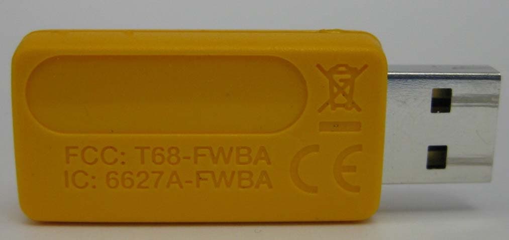
T68-FWBA
Oct 27, 2015USB1 FC WiFi-BLE Adapter
Equipment Class
DTS - Digital Transmission System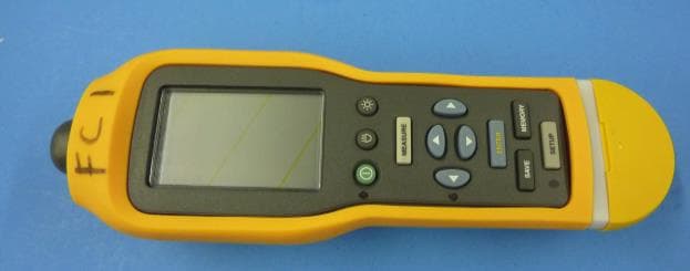
T68-805FC
May 10, 2015Vibration Meter
Equipment Class
DSS - Part 15 Spread Spectrum TransmitterT68-FBLE
Oct 27, 2013Radio Module
Equipment Class
DSS - Part 15 Spread Spectrum Transmitter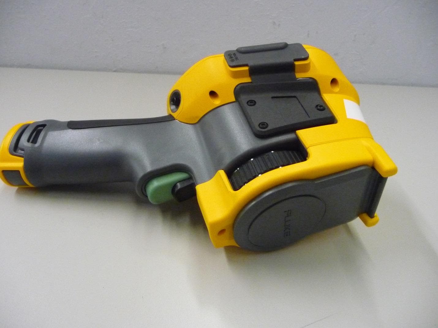
T68-FT400
Sep 29, 2013Gemini
Equipment Class
DTS - Digital Transmission System
T68-FWCS
Oct 07, 2012Radio Module
Equipment Class
DTS - Digital Transmission System