T68-F233Wireless Multimeter RDX Project
Fluke Electronics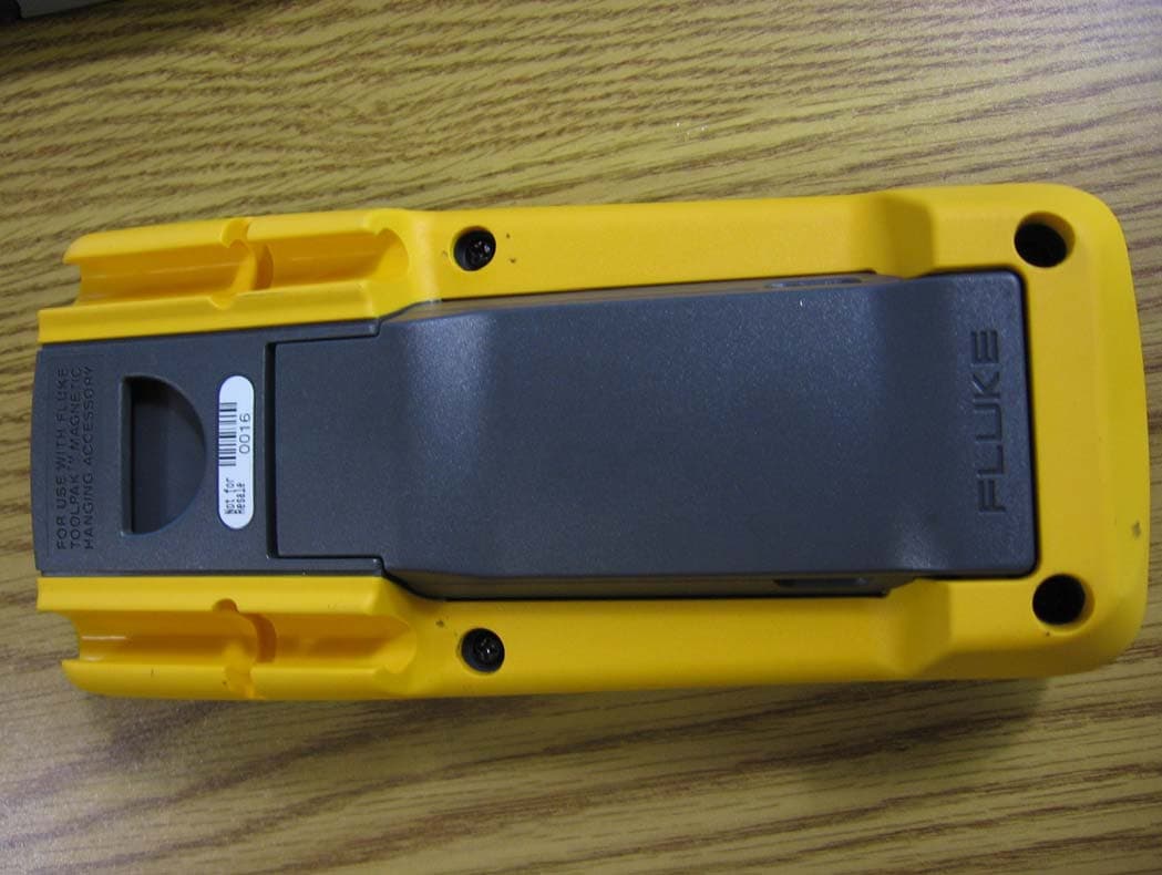
Click to zoom
Application Details
- Equipment Class
- DTS - Digital Transmission System
- Date of Grant
- Feb 03, 2010
- Application Purpose
- Original Equipment
- Date of Application
- Jan 27, 2010
- Equipment Note
- Wireless Multimeter RDX Project
- Frequency Range
- 2405.00000000 - 2480.00000000
- Company
- Fluke Electronics
- Country
- United States
Documents & Files
Document Text
Text extracted from the exhibit documents filed with the FCC. Open a document above to read the original.
Users Manual
September 2009 © 2009 Fluke Corporation. All rights reserved. Specifications are subject to change without notice. All product names are trademarks of their respective companies. 233 True-rms Remote Display Digital Multimeter Users Manual LIMITED WARRANTY AND LIMITATION OF LIABILITY This Fluke product will be free from defects in material and workmanship for three years from the date of purchase. This warranty does not cover fuses, disposable batteries, or damage from accident, neglect, misuse, alteration, contamination, or abnormal conditions of operation or handling. Resellers are not authorized to extend any other warranty on Fluke’s behalf. To obtain service during the warranty period, contact your nearest Fluke authorized service center to obtain return authorization information, then send the product to that Service Center with a description of the problem. THIS WARRANTY IS YOUR ONLY REMEDY. NO OTHER WARRANTIES, SUCH AS FITNESS FOR A PARTICULAR PURPOSE, ARE EXPRESSED OR IMPLIED. FLUKE IS NOT LIABLE FOR ANY SPECIAL, INDIRECT, INCIDENTAL OR CONSEQUENTIAL DAMAGES OR LOSSES, ARISING FROM ANY CAUSE OR THEORY. Since some states or countries do not allow the exclusion or limitation of an implied warranty or of incidental or consequential damages, this limitation of liability may not apply to you. Fluke Corporation P.O. Box 9090 Everett, WA 98206-9090 U.S.A. Fluke Europe B.V. P.O. Box 1186 5602 BD Eindhoven The Netherlands 11/99 i Table of Contents Title Page Introduction .................................................................................................................... 1 How to Contact Fluke ..................................................................................................... 1 Safety Information.......................................................................................................... 2 Warnings and Cautions ............................................................................................. 2 Radio Frequency Data............................................................................................... 5 Hazardous Voltage......................................................................................................... 6 Test Lead Alert ............................................................................................................... 6 Features ......................................................................................................................... 8 Error Messages .............................................................................................................. 12 Battery Saver™(Sleep Mode) ........................................................................................ 13 MIN MAX AVG Record Mode......................................................................................... 13 Display Hold ................................................................................................................... 14 Manual and Autoranging................................................................................................ 14 Backlight......................................................................................................................... 15 Power-Up Options .......................................................................................................... 15 233 Users Manual ii How to Make Measurements ......................................................................................... 16 AC and DC Voltage Measurements .......................................................................... 16 Resistance Measurements....................................................................................... 17 Temperature Measurements..................................................................................... 19 Continuity Tests ........................................................................................................ 19 Diode Tests............................................................................................................... 21 Capacitance Measurements..................................................................................... 23 AC and DC Current Measurements .......................................................................... 24 Frequency Measurements........................................................................................ 26 Remote Operation......................................................................................................... 26 Remove the Display Module ..................................................................................... 27 Dock the Display Module with the Meter base .......................................................... 28 Maintenance .................................................................................................................. 29 General Maintenance................................................................................................ 29 Battery Replacement................................................................................................ 29 Fuse Test .................................................................................................................. 33 Fuse Replacement.................................................................................................... 34 Service and Parts .......................................................................................................... 35 General Specifications................................................................................................... 38 Detailed Specifications.................................................................................................. 39 AC Voltage................................................................................................................ 39 DC Voltage, Conductance, and Resistance.............................................................. 40…
Text truncated - open the document above for the full version.
Block Diagram
DMM measurement block IR Interface 2.4GHz IEEE 802.15.4 RF transceiver See pg 2. antenna Impedance matching network MEASUREMENT BASE PORTION IR Interface antenna Impedance matching network DISPLAY PORTION REMOVEABLE DISPLAY LOGIC AND LCD WHEN DOCKED 16MHz 2.4GHz IEEE 802.15.4 RF transceiver See pg 2. 16MHz 1 of 2 2 of 2
Cover Letter(s)
DATE: Nov 18, 2009 Federal Communications Commission 7435 Oakland Mills Road Columbia, MD 21046 To whom it may concern: This letter is to comply with Section 0.457(d)(2)(i) and Section 0.459 pertaining to confidential material. Fluke Corporation would like the following documents regarding this submission for FCC ID: T68-F233 to be kept confidential. 1. Schematics The above material contains trade secrets or technical data, which would customarily be guarded from competitors. We do not want these documents to be accessible to the general public. Sincerely, Thomas M. Smith Senior Test Engineer Fluke Industrial Group Fluke Corporation
Cover Letter(s)
Non-Conformities FCC ID : T68-F233 (CKC CS Ref # E09-000147-FCC-01) The items listed below represent requests for information following review of this application for certification under United S tates (FCC) regulations. Further question may arise pending review of responses to these items. OK ID # Non-Conformity or Comment Submitted Response Respondent / Date of Response X C 1 The person signing the confidentiality le tter is James Cavoretto, however the contact person listed on the FCC website is Thomas Smith. In accordance with FCC Policy (KDB 852134), please provid e all cover letters signed by the authorized individual named in the applicant's grantee code information or by an authorized designee. In the latter case, please also provide letters of authorization signed by the authorized individual designating the alternate(s). In all cases, a paper trail must be demonstrated leading back to the person named under the grantee code. Provided Updated Confidentiality Letters. Thomas Smith 11/18/09 X C 2 The provided block diagram does not meet the 2.1033(b)(5) requirement, please provide a revised block diagram showing the frequency of all oscillators in the device? The tuning range(s) and intermediate frequency(ies) shall be indicated at each block. (The Schematic is not a substitute for the Block Diagram.) Provided Updated Block Diagram. Thomas Smith 11/18/09 X C 3 The schematic diagram for the display section rdx-3001_rev003_schem. pdf is labeled as "Base" . Please provide a schematic diagram for the display. The attached schematic shows both the Base and the remote. Thomas Smith 11/18/09 X TL 4 The provided internal photographs do not show the bottom side of the PCB. Please provide internal photographs showing both side of the PCB. Pictures retaken from the original EUT. On 11/18/09 Armando del angel / 11/18/09 X TL 5 Please provide legible external photograph showing all six sides of the display and all six sides of the base unit. Pictures retaken from the original EUT. On 11/18/09 Armando del angel / 11/18/09 X TL 6 In the test condition, it is not clear whether the RF Output power, Peak Power Spectral Density, bandedge compliance and radiated emission were maximized in three orthogonal orientation of the EUT. Please clarify. Being a handheld device, three orthogonal orientations were investigated. Only the values from the worst orientation were submitted. Armando del angel / 11/18/09 X TL 7 The frequency range of meas urement is listed as 30 MHz- 24.8GHz on Page 15 of test report FC09-147 and page 14 of test report FC09-149.However the schematic diagrams Test performed on the Armando del angel / shows the lowest clock crystal of 16MHz. Please provided revised test report complying with frequency range of measurement as specified in FCC15.33 original device on 11/17/09 from 9kHz to 30MHz to cover the whole spectrum. Report Addendum: Please add the corresponding attached data sheets to the FCC 15.247(d) Radiated Spurious emissions sections of both reports (FC09-147 and FC09-149). Report Addendums for FC09-147 & FC09-148 have been Provided. 11/18/09 Armando del angel / 11/19/09 CKC Labs Report Department. 11/23/09 X C 8 Page 2 of the user manual states that the device complies with FCC15.249, however the certification sought and test me thod performed is 15.247. In addition, rule part 15.207 is not applicable to battery operated devices. Please provide a revised user manual with applicable FCC rule part. . Updated Users Manual Provided. Thomas Smith 11/18/09 X C 9 The provided MPE calculation demonstrates the device meets exposure safety limit per 1.1310 at 20 cm away from the device. However the user manual does not include any RF safety precaution. Please provide a revised user manual with sufficient instructions and information for satisfying RF safety Updated Users Manual Provided. Thomas Smith 11/18/09 X C 10 Page 5 of the user manual states "... Changes or modifications to the wireless 2.4 GHz radio not expressly approved by Fluke Corporation could void the user’s authority to operate the equipment....". However 15.21 states "The users manual or instruction manual for an intentional or unintentional radiator shall caution the user that changes or modifications not expressly approved ......." Updated Users Manual Provided. Thomas Smith 11/18/09 Please provide a revised used manual meeting 15.21 requirements for the entire device. X C 11 The label exhibit shows imprinted on the base and the display unit, FCC logo meeting the label description of 15.19(b)(1)(i). In accordance with FCC 2.1074 “ Devices subject only to a Declaration of Conformity shall be uniquely identified by the responsible party. This identification shall not be of a format which could be confused with the FCC Identifier required on certified, notified, type accepted or type approved equipment.” The presented FCC logo is NOT applicable to stand along equipment subjected to verification and/or certification ( see 15.101(a) ). Please remove the FCC logo from the device. * No response from th e customer needed. Reference: http://fjallfoss.fcc.gov/oetcf/kdb/forms/FT SSearchResultPage.cfm? id=27980&switch=P Removal of the FCC marks would require two expensive tooling changes at this point. It is not possible to cover up or scratch out the logo. New inserts would need to be fabricated for two different injection molds. If at all possible we would like to leave the markings as they are. There has been a KDB inquiry opened and I believe that the FCC has okayed the Label except that we will need to put a permanent FCC identifier on the inside of the battery compartment. Thomas Smith 11/18/09 x C 12 The FCC has confirmed that a FCCID labe l need s to be permanently attached to the device, please provide a new FCCID location photograph showing placement of the label inside the battery compartment. FCC OET Tracking Number 693694 :” The Commission requires the label be in a fixed location and in most cases on the outside and…
Text truncated - open the document above for the full version.
ID Label/Location Info
Base Marking
ID Label/Location Info
Remote Head Marking
Operational Description
Fluke 233 Operational Description This Remote Display Multimeter uses two identical wireless transceivers (Freescale Semiconductor MC13201) to enable removal of the display portion of the DMM (Digital Multimeter) to remote monitor the measurements from the base unit. The transceivers are short range, low power, 2.4‐2.48 GHz Industrial, Scientific, and Medical (ISM) band transceivers and have a physical layer compliant to IEEE 802.15.4 . The packet structure is a point to point proprietary method. The transceivers includes a low noise amplifier, 1.0 mW power amplifiers (PA), onboard RF transmit/receive (T/R) switch for single port use, PLL with internal voltage controlled oscillator (VCO), on‐board power supply regulation, and full spread‐spectrum encoding and decoding. The device supports 250 kbps Offset‐Quadrature Phase Shift Keying (O‐QPSK) data in 2.0 MHz channels with 5.0 MHz channel spacing per the 802.15.4 Standard. The SPI port and interrupt request output are used for receive (RX) and transmit (TX) data transfer and control. The antennas used are 2.45GHz Ceramic Chip Antennas with a peak gain of 3.0dBi The remote display and base halves must first be initialized by the infrared communication port before the transceivers are able to communicate with each other. The products are enabled by docking the display with the base unit. Once docked and initialized, the two halves are linked to each other by address (Point to Point) Once the halves are separated, the wireless transceivers are enabled and only the two halves will communicate with each other. Two or more displays cannot be used to simultaneously communicate with a single base. The range of these transceivers is specified at 30ft but under ideal conditions my reach 100 ft. There are no additional peripheral devices supported or required.
Operational Description
Component SpecificationSpecification for P/N: 2129778 Fluke CorporationDocument Revision: 001 Part Type:Page 1 of 1 Title/Function: 1.GENERAL DESCRIPTION This document describes a 2.45GHz Ceramic Chip Antenna. Its electrical and mechanical requirements are per the attached manufacturer’s specification. 2.GENERAL REQUIREMENTS 2.1PackagingSurface Mount Tape and Reel, per EIA-481. Tape shall be made of anti-static plastic. RF Components Antenna, Ceramic Chip, Bluetooth, 2.45GHz, 3W, 50Ω LW T ab c Inches0.374 ± .0080.079 ± .0080.047 + .004/ -.0080.053 ± .008 0.043 ± .0040.010 ± .004 mm9.5 ± 0.2 2.0 ± 0.21.2 + 0.1/- 0.21.35 ± 0.21.1 ± 0.10.25 ± 0.1 Terminal Configuration 1INPUT 2NC Mechanical Dimensions “High Frequency Ceramic Solutions” 931 Via Alondra • Camarillo, CA 93012 • TEL 805.389.1166 FAX 805.389.1821 www.johanson technology.com 931 Via Alondra • Camarillo, CA 93012 • TEL 805.389.1166 FAX 805.389.1821 Input PowerImpedanceOperating Temperature RangeReel Qty 3 Watts max50 Ω-40 to +85°C1000 Part FrequencyPeak GainAve. GainReturn Number(MHz)(XZ-V)(XZ-V)Loss 2450AT45A100_2400 - 25003.0 dBi typ.1.0 dBi typ. 9.5 dB min. 2.45 GHz Chip AntennaP/N 2450AT45A100 Detail Specification Page 1 of 3 Johanson Technology, Inc. reserves the right to make design changes without notice. All sales are subject to Johanson Technology, Inc. terms and conditions. Mounting Considerations Mount these devices with brown colored side facing up. Line width should be designed to provide 50Ωimpedance matching characteristics. a) Without Matching Circuit (moderate bandwidth)b) With Matching Circuit* (wide bandwidth) *Matching circuit and component values will depend on PCB layout. “High Frequency Ceramic Solutions” www.johanson technology.com 931 Via Alondra • Camarillo, CA 93012 • TEL 805.389.1166 FAX 805.389.1821 2.45 GHz Chip AntennaP/N 2450AT45A100 Detail Specification Page 2 of 3 Test Board for Electrical Characteristic Measurements Typical Return Loss for P/N 2450AT45A100 a) Without Matching Circuitb) With Matching Circuit “High Frequency Ceramic Solutions” www.johanson technology.com 931 Via Alondra • Camarillo, CA 93012 • TEL 805.389.1166 FAX 805.389.1821 2.45 GHz Chip AntennaP/N 2450AT45A100 Detail Specification Page 3 of 3 Typical Radiation Patterns for P/N 2450AT45A100
Operational Description
© Freescale Semiconductor, Inc., 2005, 2006, 2007, 2008. All rights reserved. Freescale Semiconductor Technical Data Freescale reserves the right to change the detail specifications as may be required to permit improvements in the design of its products. Document Number: MC13201 Rev. 1.3, 04/2008 MC13201 Package Information Plastic Package Case 1311-03 QFN -32 Ordering Information DeviceDevice MarkingPackage MC13201FC13201QFN-32 MC13201FCR2 (Tape and Reel) 13201QFN-32 1Introduction The MC13201 is a short range, low power, 2.4 GHz Industrial, Scientific, and Medical (ISM) band transceivers. The MC13201 contains a complete packet data modem which is compliant with the IEEE ® 802.15.4 Standard PHY (Physical) layer. This allows the development of proprietary point-to-point and star networks based on the 802.15.4 packet structure and modulation format. For full 802.15.4 Standard compliance, the MC13202 and Freescale's 802.15.4 MAC software are required. When combined with an appropriate microcontroller (MCU), the MC13201 provides a cost-effective solution for short-range data links and networks. Interface with the MCU is accomplished using a four wire serial peripheral interface (SPI) connection and an interrupt request output which allows for the use of a variety of processors. The software and processor can be scaled to fit applications ranging from simple point-to-point systems to star networks. MC13201 2.4 GHz Low Power Transceiver for the IEEE ® 802.15.4 Standard Contents 1 Introduction . . . . . . . . . . . . . . . . . . . . . . . . . . 1 2 Features . . . . . . . . . . . . . . . . . . . . . . . . . . . . . 2 3 Block Diagrams . . . . . . . . . . . . . . . . . . . . . . . 4 4 Data Transfer Mode . . . . . . . . . . . . . . . . . . . . 5 5 Electrical Characteristics . . . . . . . . . . . . . . . 7 6 Functional Description . . . . . . . . . . . . . . . . 10 7 Pin Connections . . . . . . . . . . . . . . . . . . . . . . 14 8 Crystal Oscillator Reference Frequency . . 18 9 Packaging Information . . . . . . . . . . . . . . . . . 27 MC13201 Technical Data, Rev. 1.3, 2Freescale Semiconductor For more detailed information about MC13201 operation, refer to the MC13201 Reference Manual, (MC13201RM). Applications include, but are not limited to, the following: •Residential and commercial automation — Lighting control — Security — Access control — Heating, ventilation, air-conditioning (HVAC) — Automated meter reading (AMR) •Industrial Control — Asset tracking and monitoring — Homeland security — Process management — Environmental monitoring and control —HVAC — Automated meter reading •Health Care — Patient monitoring — Fitness monitoring •Consumer — Human interface devices (keyboard, mice, etc.) — Remote control — Wireless toys The transceiver includes a low noise amplifier, 1.0 mW power amplifiers (PA), onboard RF transmit/receive (T/R) switch for single port use, PLL with internal voltage controlled oscillator (VCO), on-board power supply regulation, and full spread-spectrum encoding and decoding. The device supports 250 kbps Offset-Quadrature Phase Shift Keying (O-QPSK) data in 2.0 MHz channels with 5.0 MHz channel spacing per the 802.15.4 Standard. The SPI port and interrupt request output are used for receive (RX) and transmit (TX) data transfer and control. 2Features •Recommended power supply range: 2.0 to 3.4 V •Fully compliant 802.15.4 Standard transceiver supports 250 kbps O-QPSK data in 5.0 MHz channels and full spread-spectrum encode and decode •Operates on one of 16 selectable channels in the 2.4 GHz band •-1 to 0 dBm nominal output power, programmable from -27 dBm to +3 dBm typical •Receive sensitivity of <-91 dBm (typical) at 1% PER, 20-byte packet, much better than the 802.15.4 Standard of -85 dBm MC13201 Technical Data, Rev. 1.3, Freescale Semiconductor3 •Integrated transmit/receive switch •Dual PA output pairs which can be programmed for full differential single port or dual port operation that supports an external LNA and/or PA •Three power down modes for increased battery life — < 1 μA Off current — 1.0 μA Typical Hibernate current — 35 μA Typical Doze current (no CLKO) •Programmable frequency clock output (CLKO) for use by MCU •Onboard trim capability for 16 MHz crystal reference oscillator eliminates need for external variable capacitors and allows for automated production frequency calibration •Four internal timer comparators available to supplement MCU timer resources •Buffered transmit and receive data packets for simplified use with low cost MCUs •Seven GPIO to supplement MCU GPIO •Operating temperature range: -40 °C to 85 °C •Small form factor QFN-32 Package — Meets moisture sensitivity level (MSL) 3 — 260 °C peak reflow temperature — Meets lead-free requirements 2.1Software Support Freescale provides a software suite to complement the MC13201 hardware which is called the Freescale Simple MAC (SMAC): •Simple proprietary wireless connectivity. •Small memory footprint (about 3 Kbytes typical) •Supports point-to-point and star network configurations •Proprietary networks •Source code and application examples provided MC13201 Technical Data, Rev. 1.3, 4Freescale Semiconductor 3Block Diagrams Figure 1 shows a simplified block diagram of the MC13201 which is an 802.15.4 Standard compatible transceiver that provides the functions required in the physical layer (PHY) specification. Figure 1. 802.15.4 modem Simplified Block Diagram Figure 2 shows the basic system block diagram for the MC13201 in an application. Interface with the transceiver is accomplished through a 4-wire SPI port and interrupt request line. The media access control (MAC), drivers, and network and application software (as required) reside on the host processor. The host can vary from a simple 8-bit device up to a sophisticated 32-bit processor depending on application requirements. Figure 2. System Level Block Diagram Phase Shift M odulator RST GPIO1 GPIO2 GPIO3 GPIO4 XTAL2 XTAL1 RFIN_M (PAO_M ) PAO_P PAO_M MOSI MIS…
Text truncated - open the document above for the full version.
RF Exposure Info
Page 1 of 5 Report No: MAXIMUM PERMISSIBLE EXPOSURE REPORT FOR THE FCC ID: T68-F233 IC: 6627A-F233 WIRELESS MULTIMETER RDX PROJECT - BASE MODEL NUMBER: 233 DATE OF ISSUE: 11/13/09 PREPARED FOR: Fluke Corporation 6920 Seaway Blvd. Everett WA 98203 PREPARED BY: CKC Laboratories, Inc. 5046 Sierra Pines Drive Mariposa, CA 95338 W.O. No.: 89609 Report No.: FC09-149-R Page 2 of 5 Report No: Purpose of Test: To demonstrate compliance with United States and Canada RF Exposure requirements for Mobile Equipment (devices used >20cm from the body), where Maximum Permissible Exposure (MPE) Calculations apply. United States MPE Limits in accordance with 1.1310: Occupational / Controlled Exposure Frequency Range (MHz) Electric Field Strength (V/m) Magnetic Field Strength (A/m) Power Density (mW/cm 2 ) Averaging Time (minutes) 0.3-3.0 614 1.63 *(100) 6 3.0-30 1842/f 4.89/f *(900/f2) 6 30-300 61.4 0.163 1 6 300-1500 --- --- f/300 6 1500-100,000 --- --- 5 6 General Population / Uncontrolled Exposure Frequency Range (MHz) Electric Field Strength (V/m) Magnetic Field Strength (A/m) Power Density (mW/cm 2 ) Averaging Time (minutes) 0.3-1.34 614 1.63 *(100) 30 1.34-30 824/f 2.19/f *(180/f2) 30 30-300 27.5 0.073 0.2 30 300-1500 --- --- f/1500 30 1500-100,000 --- --- 1 30 Note: Limit is calculated based on the mid-band frequency used in the operating frequency range. Page 3 of 5 Report No: Canadian MPE Limits in accordance with RSS-102: Occupational / Controlled Exposure: General Population / Uncontrolled Exposure Page 4 of 5 Report No: Equipment operational details: Operating Frequency (MHz) Measured Output Power (dBm) Maximum Mobile Antenna Gain (dBi) Maximum EIRP (dBm) 2405-2480 -4.7 3 -1.7 Measurements based from EMC Test Report: CKC Laboratories, Inc., test report #: FC09-149 Device and Antenna Operating Configuration: Device operating at maximum output power with continuous transmission of modulated data. Tranceiver. Base part of wireless multimeter. Two internal, no user- removable, 3dBi antennas installed. Test Procedure: This equipment is evaluated in accordance with the guidelines set forth in OET Guide 65 & ANSI C95.1 for the US and Health Canada Safety Code 6 & RSS 102 for Canada. Other Considerations: None Device stops transmitting and receiving as soon as the display is docked to it. . . MPE Calculations: Limit used: Occupational / Controlled Exposure X General Population / Uncontrolled Exposure MPE Limit = 1 (mW/cm 2 ) 2 2 4 )/( d EIRP cmmWDensityPower Given: EIRP in mW and d in cm EIRP (mW) Distance (cm) Power Density (mW/cm 2 ) Limit (mW/cm 2 ) Power Density (W/m 2 ) Limit (W/m 2 ) 0.67 20 0.000133 1 0.00133 10 Page 5 of 5 Report No: Statement of Compliance: This device demonstrates compliance under the operating conditions specified in this document. Under normal operating conditions, the antenna is designed to be installed in accordance with the manufacturer’s instructions in such a manor to maintain the minimum separation distance. The MPE calculations shown above demonstrate compliance to the provisions of US and Canadian requirements. As can be seen from the MPE results, this device passes the specified limits at a distance of 20cm at the maximum output power under normal operating conditions.
RF Exposure Info
Page 1 of 5 Report No:FC09-147- R MAXIMUM PERMISSIBLE EXPOSURE REPORT FLUKE CORPORATION FOR THE WIRELESS MULTIMETER RDX PROJECT – DISPLAY, 233 FCC ID: T68-F233 IC: 6627A-F233 MODEL NUMBER: 233 DATE OF ISSUE: NOVEMBER 13, 2009 PREPARED FOR: Fluke Corporation 6920 Seaway Blvd. Everett WA 98203 PREPARED BY: CKC Laboratories, Inc. 5046 Sierra Pines Drive Mariposa, CA 95338 W.O. No.: 89608 Report No.: FC09-147-R Page 2 of 5 Report No:FC09-147- R Purpose of Test: To demonstrate compliance with United States and Canada RF Exposure requirements for Mobile Equipment (devices used >20cm from the body), where Maximum Permissible Exposure (MPE) Calculations apply. United States MPE Limits in accordance with 1.1310: Occupational / Controlled Exposure Frequency Range (MHz) Electric Field Strength (V/m) Magnetic Field Strength (A/m) Power Density (mW/cm 2 ) Averaging Time (minutes) 0.3-3.0 614 1.63 *(100) 6 3.0-30 1842/f 4.89/f *(900/f2) 6 30-300 61.4 0.163 1 6 300-1500 --- --- f/300 6 1500-100,000 --- --- 5 6 General Population / Uncontrolled Exposure Frequency Range (MHz) Electric Field Strength (V/m) Magnetic Field Strength (A/m) Power Density (mW/cm 2 ) Averaging Time (minutes) 0.3-1.34 614 1.63 *(100) 30 1.34-30 824/f 2.19/f *(180/f2) 30 30-300 27.5 0.073 0.2 30 300-1500 --- --- f/1500 30 1500-100,000 --- --- 1 30 Note: Limit is calculated based on the mid-band frequency used in the operating frequency range. Page 3 of 5 Report No:FC09-147- R Canadian MPE Limits in accordance with RSS-102: Occupational / Controlled Exposure: General Population / Uncontrolled Exposure Page 4 of 5 Report No:FC09-147- R Equipment operational details: Operating Frequency (MHz) Measured Output Power (dBm) Maximum Mobile Antenna Gain (dBi) Maximum EIRP (dBm) 2405-2480 6.661 3 9.661 Measurements based from EMC Test Report: CKC Laboratories, Inc., test report #: FC09-147 Device and Antenna Operating Configuration: Device operating at maximum output power with continuous transmission of modulated data. Antenna is integral with an antenna gain of 3dBi peak (1.99 linear). Test Procedure: This equipment is evaluated in accordance with the guidelines set forth in OET Guide 65 & ANSI C95.1 for the US and Health Canada Safety Code 6 & RSS 102 for Canada. Other Considerations: None . . MPE Calculations: Limit used: Occupational / Controlled Exposure X General Population / Uncontrolled Exposure MPE Limit = 1 (mW/cm 2 ) 2 2 4 )/( d EIRP cmmWDensityPower Given: EIRP in mW and d in cm EIRP (mW) Distance (cm) Power Density (mW/cm 2 ) Limit (mW/cm 2 ) Power Density (W/m 2 ) Limit (W/m 2 ) 9.25 20 0.00184 1.0 0.0184 10 Page 5 of 5 Report No:FC09-147- R Statement of Compliance: This device demonstrates compliance under the operating conditions specified in this document. Under normal operating conditions, the antenna is designed to be installed in accordance with the manufacturer’s instructions in such a manor to maintain the minimum separation distance. The MPE calculations shown above demonstrate compliance to the provisions of US and Canadian requirements. As can be seen from the MPE results, this device passes the specified limits at a distance of 20cm at the maximum output power under normal operating conditions.
Test Report
Page 1 of 34 Report No: FC09-149A TESTING CERT #803.01, 803.02, 803.05, 803.06 ADDENDUM TO FLUKE CORPORATION TEST REPORT FC09-149 FOR THE WIRELESS MULTIMETER (BASE), FLUKE 233 FCC PART 15 SUBPART C SECTION 15.247 AND RSS-210 ISSUE 7 TESTING DATE OF ISSUE: NOVEMBER 23, 2009 PREPARED FOR: Fluke Corporation 6920 Seaway Blvd. Everett, WA 98203 PREPARED BY: Mary Ellen Clayton CKC Laboratories, Inc. 5046 Sier…
Text truncated - open the document above for the full version.
Contact Information
Applicant
James E Lenker(Test Engineer)
Technical Contact
CKC Certification Services, LLCJessina Hunter
[email protected]209-966-5240
5046 Sierra Pines Dr. · Mariposa · United States
Test Firm
CKC Laboratories, Inc.Steve Behm
Technical Specifications
| # | Rule Parts | Frequency Range | Power Output |
|---|---|---|---|
| 2 | 15C | 2.40 GHz - 2.48 GHz | 4.60 mW |
Other Applications from Fluke Electronics
T68-FWBA
Oct 27, 2015USB1 FC WiFi-BLE Adapter
Equipment Class
DTS - Digital Transmission System
T68-FT560
May 14, 2015TiX560, TiX520
Equipment Class
DSS - Part 15 Spread Spectrum Transmitter
T68-805FC
May 10, 2015Vibration Meter
Equipment Class
DSS - Part 15 Spread Spectrum TransmitterT68-FBLE
Oct 27, 2013Radio Module
Equipment Class
DSS - Part 15 Spread Spectrum Transmitter
T68-FT400
Sep 29, 2013Gemini
Equipment Class
DTS - Digital Transmission System