T68-FWCSRadio Module
Fluke Electronics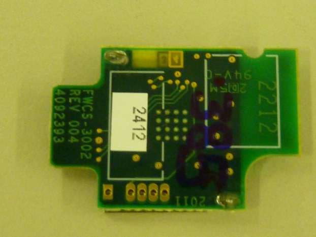
Click to zoom
Application Details
- Equipment Class
- DTS - Digital Transmission System
- Date of Grant
- Oct 07, 2012
- Application Purpose
- Original Equipment
- Date of Application
- Oct 01, 2012
- Equipment Note
- Radio Module
- Frequency Range
- 2405.00000000 - 2480.00000000
- Company
- Fluke Electronics
- Country
- United States
Documents & Files
Document Text
Text extracted from the exhibit documents filed with the FCC. Open a document above to read the original.
Users Manual
Fluke FWCS Radio Transceiver Module Integration Manual J. Swanzy August 18, 2012 The Fluke wireless communication system (FWCS) radio module is a proprietary IEEE 802.15.4 type low power (< 1mW) radio that is approved for exclusive use in Fluke products. The range of the radio module is specified at 30ft but under ideal conditions my reach 100 ft. The RF packet structure incorporates a point to point proprietary method allowing communication with other Fluke instruments using the same packet structure technique. The radio module is marked with the Fluke internal model number (FWCS). All Fluke products using the radio module must display the FCC and Industry Canada certification number on the outside of an enclosure where it is visible by a user. All radio module settings and protocols are programmed at the time of manufacturing assembly and cannot be modified by a user. The radio module allows Fluke products to work together to collect analog measurement data and pass the data to a central controller (another test and measurement product) for storage and display. The radio module is not intended to be sold commercially or used in products without the Fluke brand. All radio components are mounted on a single 25mm x 10mm PCB. The module contains the transceiver IC (RF transmit and receive), a voltage regulator, and an antenna. The transceiver and regulator circuits are covered by a metal shield soldered to the PCB. The transceiver IC (Texas Instruments CC2530F256) has an RF core that controls the internal radio segments. In addition, it provides an interface between a core 8051 MCU and the other radio circuits. This makes it possible to issue commands, read status, and automate and sequence radio events. The transceiver includes a low noise amplifier, software controlled power amplifier, onboard RF transmit/receive, phase lock loop with internal voltage controlled oscillator, an internal IC power supply regulation, and full spread-spectrum encoding and decoding. The transceiver IC is programmable in 1-MHz steps with 5.0 MHz channel spacing per the 802.15.4 standard. The transceiver IC also includes a packet-filtering and address-recognition capability. The antenna is a 2.45GHz ceramic chip antenna with a peak gain of 3.0dBi. The antenna is the only component that is not mounted under the metal shield. The antenna is a single ceramic chip type and also soldered to the PCB. The radio module is intended to be plugged into a host where the host CPU must communicate to the radio module through a serial peripheral interface (SPI). The SPI provides communication path for receive (RX) and transmit (TX) data transfer and control. The radio module must first be initialized by the host CPU before the transceiver is able to communicate with other Fluke products. The radio will automatically cease operation and thus communication once battery capacity reaches a specified minimum threshold. The module is used in a family of products made by Fluke Corporation and branded Fluke. All radio protocols and module-host communication protocols are Fluke proprietary and not available to the public. Regulatory statements that must be in every User Manual of a Fluke product using the radio module are as follows: FCC Changes or modifications to the wireless 2.4 GHz radio not expressly approved by Fluke Corporation could void the user's authority to operate the equipment. This device complies with Part 15 of the FCC Rules. Operation is subject to the two conditions that follow: 1. This device can not cause interference. 2. This device must accept any interference, including interference that can cause undesired operation of the device. Class B digital device: A digital device that is marketed for operation in a residential environment notwithstanding use in commercial, business and industrial environments. Examples of such devices include, but are not limited to, personal computers, calculators, and equivalent electronic devices that are marketed for operation by the general public. The Meter was tested and found to comply with the limits for a Class B digital device, pursuant to Part 15 of the FCC Rules. These limits are designed to provide reasonable protection against harmful interference in a residential installation. This equipment generates, uses, and can radiate radio frequency energy and, if not installed and used in accordance with the instructions, can cause harmful interference to radio communications. However, there is no guarantee that interference will not occur in a particular installation. If this equipment does cause harmful interference to radio or television reception, which can be determined by turning the equipment off and on, the user is encouraged to try to correct the interference by one or more of the measures that follow: Reorient or relocate the receiving antenna. Increase the separation between the equipment and receiver. Consult the dealer or an experienced radio/TV technician for help. Exposure to RF Energy THIS MODEL DEVICE MEETS U.S. AND INTERNATIONAL REQUIREMENTS FOR EXPOSURE TO RADIO FREQUENCY RADIATION. The FWCS is a radio transmitter and receiver. It is designed and manufactured not to exceed the emission limits for exposure to radio frequency (RF) energy set by the Federal Communications Commission of the U.S. Government and by the International Commission on Non-Ionizing Radiation Protection (ICNIRP). The device also meets the European Radio and Telecommunications Terminal Equipment (R&TTE) directive, for protecting the health and safety of the user and other persons. These limits are part of comprehensive guidelines that establish permitted levels of RF energy for the general population. The guidelines are based on standards that were developed by independent scientific organizations through periodic and thorough evaluation of scientific studies. The standards include a substantial safety margin designed to assure the safety of all persons, regardless of age and health. Before …
Text truncated - open the document above for the full version.
Attestation Statements
Fluke Corporation Telephone Facsimile Email PO Box 9090 Everett WA 98206.9090 USA 425.347.6100 425.356.5108 http//www.fluke.com Date: July 30, 2012 Federal Communications Commission 7435 Oakland Mills Road Columbia, MD 21046 and Industry Canada | Industrie Canada 3701 Carling Avenue, Ottawa ON K2H 8S2 | 3701, avenue Carling PO Box 11490, Station H, Ottawa ON K2H 8S2 To Whom It May Concern: I appoint Suresh Kondapalli of TUV Rheinland of North America to act as our agent in the preparation of this application for equipment certification. I certify that submitted documents properly describe the device or system for which equipment certification is sought. I also certify that each unit manufactured, imported or marketed, as defined in the FCC or Industry Canada’s regulations will have affixed to it a label identical to that submitted for approval with this application. For instances where our authorized agent signs the application for certification on our behalf, I acknowledge that all responsibility for complying with the terms and conditions for Certification, as specified by TUV Rheinland. For TCB applications, We certify that we are not subject to denial of federal benefits, that includes FCC benefits, pursuant to Section 5301 of the Anti-Drug Abuse Act of 1988, 21 U.S.C. 862. Further, no party, as defined in 47 CFR 1.2002 (b), to the application is subject to denial of federal benefits, that includes FCC benefits. Thank you, Agency Agreement Expiration Date: August 1, 2013 By: __________________________ Joe Swanzy (Signature) (Print name) Title: Product Evaluation Manager Telephone: 4254465626 On behalf of: Fluke Corporation 6920 Seaway Blvd. (425)446-5626 Everett, WA 98203 USA
Cover Letter(s)
Fluke Corporation Telephone Facsimile Email PO Box 9090 Everett WA 98206.9090 USA 425.347.6100 425.356.5108 http//www.fluke.com Date: August 30, 2012 Federal Communications Commission 7435 Oakland Mills Road Columbia, MD 21046 and Industry Canada | Industrie Canada 3701 Carling Avenue, Ottawa ON K2H 8S2 | 3701, avenue Carling PO Box 11490, Station H, Ottawa ON K2H 8S2 To Whom It May Concern: Subject: Confidentiality Request for FCC ID: T68-FWCS IC: 6627A-FWCS Pursuant to FCC 47 CRF 0.457(d) and 0.459 and IC RSP-100, Section 10, the applicant requests that a part of the subject FCC/IC application be held confidential. Type of Confidentiality Requested Exhibit Short Term Permanent Block Diagrams Short Term Permanent Internal Photos Short Term Permanent Operation Description/Theory of Operation Short Term Permanent Tune-Up Procedure Short Term Permanent Schematics Short Term Permanent User’s Manual Fluke Corporation has spent substantial effort in developing this product and it is one of the first of its kind in industry. Having the subject information easily available to "competition" would negate the advantage they have achieved by developing this product. Not protecting the details of the design will result in financial hardship. Permanent Confidentiality: The applicant requests the exhibits listed above as permanently confidential be permanently withheld from public review due to materials that contain trade secrets and proprietary information not customarily released to the public. Short-Term Confidentiality: The applicant requests the exhibits selected above as short term confidential be withheld from public view for a period of ___(specify number of days not to exceed 180) ___ days from the date of the Grant of Equipment Authorization and prior to marketing. This is to avoid premature release of sensitive information prior to marketing or release of the product to the public. Applicant is also aware that they are responsible to notify TUV Rheinland in the event information regarding the product or the product is made available to the public. TUV Rheinland will then release the documents listed above for public disclosure pursuant to FCC Public Notice DA 04-1705. Fluke Corporation Telephone Facsimile Email PO Box 9090 Everett WA 98206.9090 USA 425.347.6100 425.356.5108 http//www.fluke.com By: __________________________ Joe Swanzy (Signature) (Print name) Title: Product Evaluation Manager Telephone: 4254465626 On behalf of: Fluke Corporation 6920 Seaway Blvd. (425)446-5626 Everett, WA 98203 USA
Cover Letter(s)
Fluke Corporation Telephone Facsimile Email PO Box 9090 Everett WA 98206.9090 USA 425.347.6100 425.356.5108 http//www.fluke.com Date: August 2, 2012 To: Federal Communications Commission 7435 Oakland Mills Road Columbia, MD 21046 Re: Modular Approval Letter for Fluke FWCS Radio Module To Whom It May Concern: In accordance with Section 15.212 (b), Fluke Corpoartion believes it has met all of the requirements set out in that document for the granting of single modular approval. Specifically, the criteria set out in that document are addressed below in bold: 1. The modular transmitter must have its own RF shielding. This is intended to ensure that the module does not have to rely upon the shielding provided by the device into which it is installed in order for all modular transmitter emissions to comply with Part 15 limits. It is also intended to prevent coupling between the RF circuitry of the module and any wires or circuits in the device into which the module is installed. Such coupling may result in non-compliant operation. The Fluke FWCS radio module has its own shielding covering all critical RF components. This can be seen in the photographs included in the accompanying test report. 2. The modular transmitter must have buffered modulation/data inputs (if such inputs are provided) to ensure that the module will comply with Part 15 requirements under conditions of excessive data rates or over-modulation. The Fluke FWCS radio module has buffered modulation/data inputs provided by the Ti CC2530F128 transceiver IC component. 3. The modular transmitter must have its own power supply regulation. This is intended to ensure that the module will comply with Part 15 requirements regardless of the design of the power supplying circuitry in the device into which the module is installed. The Fluke FWCS radio module incorporates its own supply regulation and the Ti TPS 77028 IC component provides this. 4. The modular transmitter must comply with the antenna requirements of Section 15.203 and 15.204(c). The antenna must either be permanently attached or employ a “unique” antenna coupler (at all connections between the module and the antenna, including the cable). Any Fluke Corporation Telephone Facsimile Email PO Box 9090 Everett WA 98206.9090 USA 425.347.6100 425.356.5108 http//www.fluke.com antenna used with the module must be approved with the module, either at the time of initial authorization or through Class II permissive change. The “professional installation” provision of Section 15.203 may not be applied to modules. The Fluke FWCS radio module employs a “unique” antenna coupler (at all connections between the module and the antenna, including the cable). All antennas have been verified at the time of initial authorization. 5. The modular transmitter must be tested in a stand-alone configuration, i.e., the module must not be inside another device during the testing. This is intended to demonstrate that the module is capable of complying with Part 15 emission limits regardless of the device into which it is eventually installed. Unless the transmitter module will be battery powered, it must comply with the AC line conducted requirements found in Section 15.207. AC or DC power lines and data input/output lines connected to the module must not contain ferrites, unless they will be marketed with the module (see Section 15.27(a)). The length of these lines shall be length typical of actual use or, if that length is unknown, at least 10 centimeters to insure that there is no coupling between the case of the module and supporting equipment. Any accessories, peripherals, or support equipment connected to the module during testing shall be unmodified or commercially available (see Section 15.31(i)). Fluke FWCS radio module was tested with a test jig and Fluke FWCS radio module does not employ any ferrites. 6. The modular transmitter must be labeled with its own FCC ID number, and, if the FCC ID is not visible when the module is installed inside another device, then the outside of the device into which the module is installed must also display a label referring to the enclosed module. This exterior label can use wording such as the following: “Contains Transmitter Module FCC ID: “XYZMODEL1” or “Contains FCC ID: XYZMODEL1.” Any similar wording that expresses the same meaning may be used. The Grantee may either provide such a label, an example of which must be included in the application for equipment authorization, or, must provide adequate instructions along with the module which explain this requirement. In the latter case, a copy of these instructions must be included in the application for equipment authorization. The Fluke FWCS radio module is fitted with its own Fluke label and the FCC ID number is enclosure on products that contain the module. 7. The modular transmitter must comply with any specific rule or operating requirements applicable to the transmitter and the manufacturer must provide adequate instructions along with the module to explain any such requirements. A copy of these instructions must be included in the application for equipment authorization. For example, there are very strict operational and timing requirements that must be met before a transmitter is authorized for operation under Section 15.231. For instance, data transmission is prohibited, except for operation Section 15.231(e), in which case there are separate field strength level and timing requirements. Compliance with these requirements must be assured. The modules have been tested to comply with all rules under Part 15.247 The compliance is assured by the design of the device and the user is unable to intervene to cause the device to operate incorrectly. Fluke Corporation Telephone Facsimile Email PO Box 9090 Everett WA 98206.9090 USA 425.347.6100 425.356.5108 http//www.fluke.com 8. The modular transmitter must comply with any applicable RF exposure requirements. For example, FCC Rules Sections 2.1091, 2.1093 and spe…
Text truncated - open the document above for the full version.
External Photos
External Photos FCC ID: T68-FWCS IC: 6627A-FWCS
ID Label/Location Info
Radio Module Label and Location FCC ID: T68-FWCS IC: 6627A-FWCS Label Location
Internal Photos
INTERNAL PHOTOs EXHIBIT FCC ID: T68-FWCS IC: 6627A-FWCS Shields Removed
Parts List/Tune Up Info
Component SpecificationSpecification for P/N: 2129778 Fluke CorporationDocument Revision: 001 Part Type:Page 1 of 1 Title/Function: 1.GENERAL DESCRIPTION This document describes a 2.45GHz Ceramic Chip Antenna. Its electrical and mechanical requirements are per the attached manufacturer’s specification. 2.GENERAL REQUIREMENTS 2.1PackagingSurface Mount Tape and Reel, per EIA-481. Tape shall be made of anti-static plastic. RF Components Antenna, Ceramic Chip, Bluetooth, 2.45GHz, 3W, 50Ω LW T ab c Inches0.374 ± .0080.079 ± .0080.047 + .004/ -.0080.053 ± .008 0.043 ± .0040.010 ± .004 mm9.5 ± 0.2 2.0 ± 0.21.2 + 0.1/- 0.21.35 ± 0.21.1 ± 0.10.25 ± 0.1 Terminal Configuration 1INPUT 2NC Mechanical Dimensions “High Frequency Ceramic Solutions” 931 Via Alondra • Camarillo, CA 93012 • TEL 805.389.1166 FAX 805.389.1821 www.johanson technology.com 931 Via Alondra • Camarillo, CA 93012 • TEL 805.389.1166 FAX 805.389.1821 Input PowerImpedanceOperating Temperature RangeReel Qty 3 Watts max50 Ω-40 to +85°C1000 Part FrequencyPeak GainAve. GainReturn Number(MHz)(XZ-V)(XZ-V)Loss 2450AT45A100_2400 - 25003.0 dBi typ.1.0 dBi typ. 9.5 dB min. 2.45 GHz Chip AntennaP/N 2450AT45A100 Detail Specification Page 1 of 3 Johanson Technology, Inc. reserves the right to make design changes without notice. All sales are subject to Johanson Technology, Inc. terms and conditions. Mounting Considerations Mount these devices with brown colored side facing up. Line width should be designed to provide 50Ωimpedance matching characteristics. a) Without Matching Circuit (moderate bandwidth)b) With Matching Circuit* (wide bandwidth) *Matching circuit and component values will depend on PCB layout. “High Frequency Ceramic Solutions” www.johanson technology.com 931 Via Alondra • Camarillo, CA 93012 • TEL 805.389.1166 FAX 805.389.1821 2.45 GHz Chip AntennaP/N 2450AT45A100 Detail Specification Page 2 of 3 Test Board for Electrical Characteristic Measurements Typical Return Loss for P/N 2450AT45A100 a) Without Matching Circuitb) With Matching Circuit “High Frequency Ceramic Solutions” www.johanson technology.com 931 Via Alondra • Camarillo, CA 93012 • TEL 805.389.1166 FAX 805.389.1821 2.45 GHz Chip AntennaP/N 2450AT45A100 Detail Specification Page 3 of 3 Typical Radiation Patterns for P/N 2450AT45A100
Parts List/Tune Up Info
CC2530F32, CC2530F64 CC2530F128, CC2530F256 www.ti.comSWRS081B–APRIL2009–REVISEDFEBRUARY2011 A TrueSystem-on-ChipSolutionfor2.4-GHzIEEE802.15.4andZigBeeApplications CheckforSamples:CC2530F32, CC2530F64, CC2530F128, CC2530F256 1 FEATURES –IEEE802.15.4MACTimer,General-Purpose Timers(One16-Bit,Two8-Bit) 2345 •RF/Layout –IRGenerationCircuitry –2.4-GHzIEEE802.15.4CompliantRF Transceiver–32-kHzSleepTimerWithCapture –ExcellentReceiverSensitivityand–CSMA/CAHardwareSupport RobustnesstoInterference –AccurateDigitalRSSI/LQISupport –ProgrammableOutputPowerUpto4.5dBm –BatteryMonitorandTemperatureSensor –VeryFewExternalComponents –12-BitADCWithEightChannelsand –Onlya SingleCrystalNeededforConfigurableResolution AsynchronousNetworks –AESSecurityCoprocessor –6-mm×6-mmQFN40Package –TwoPowerfulUSARTsWithSupportfor –SuitableforSystemsTargetingComplianceSeveralSerialProtocols WithWorldwideRadio-Frequency –21General-PurposeI/OPins Regulations:ETSIEN300328andEN300 (19×4 mA,2×20mA) 440(Europe),FCCCFR47Part15(US)and –WatchdogTimer ARIBSTD-T-66(Japan) •DevelopmentTools •LowPower –CC2530DevelopmentKit –Active-ModeRX(CPUIdle):24mA –CC2530ZigBee ® DevelopmentKit –ActiveModeTXat1 dBm(CPUIdle):29mA –CC2530RemoTI™DevelopmentKitfor –PowerMode1 (4μs Wake-Up):0.2mA RF4CE –PowerMode2 (SleepTimerRunning):1μA –SmartRF™Software –PowerMode3 (ExternalInterrupts):0.4μA –PacketSniffer –WideSupply-VoltageRange(2V–3.6V) –IAREmbeddedWorkbench™Available •Microcontroller –High-PerformanceandLow-Power8051APPLICATIONS MicrocontrollerCoreWithCodePrefetch •2.4-GHzIEEE802.15.4Systems –32-,64-,128-,or256-KB •RF4CERemoteControlSystems(64-KBFlash andHigher) In-System-ProgrammableFlash •ZigBeeSystems(256-KBFlash) –8-KBRAMWithRetentioninAllPower •Home/BuildingAutomation Modes •LightingSystems –HardwareDebugSupport •IndustrialControlandMonitoring •Low-PowerWirelessSensorNetworks •Peripherals •ConsumerElectronics –PowerfulFive-ChannelDMA •HealthCare –IntegratedHigh-PerformanceOp-Ampand Ultralow-PowerComparator 1 Pleasebeawarethatanimportantnoticeconcerningavailability,standardwarranty,andusein criticalapplicationsofTexas Instrumentssemiconductorproductsanddisclaimerstheretoappearsattheendofthisdatasheet. 2RemoTI,SmartRF,Z-StackaretrademarksofTexasInstruments. 3IAREmbeddedWorkbenchis a trademarkofIARSystemsAB. 4ZigBeeis a registeredtrademarkoftheZigBeeAlliance. 5Allothertrademarksarethepropertyoftheirrespectiveowners. PRODUCTIONDATAinformationis currentasofpublicationdate. ©2009–2011,TexasInstrumentsIncorporated ProductsconformtospecificationsperthetermsoftheTexas Instrumentsstandardwarranty.Productionprocessingdoesnot necessarilyincludetestingofallparameters. CC2530F32, CC2530F64 CC2530F128, CC2530F256 SWRS081B–APRIL2009–REVISEDFEBRUARY2011www.ti.com DESCRIPTION TheCC2530isa truesystem-on-chip(SoC)solutionforIEEE802.15.4,ZigbeeandRF4CEapplications.It enablesrobustnetworknodestobebuiltwithverylowtotalbill-of-materialcosts.TheCC2530combinesthe excellentperformanceofa leadingRFtransceiverwithanindustry-standardenhanced8051MCU,in-system programmableflashmemory,8-KBRAM,andmanyotherpowerfulfeatures.TheCC2530comesin fourdifferent flashversions:CC2530F32/64/128/256,with32/64/128/256KBofflashmemory,respectively.TheCC2530has variousoperatingmodes,makingit highlysuitedforsystemswhereultralowpowerconsumptionisrequired. Shorttransitiontimesbetweenoperatingmodesfurtherensurelowenergyconsumption. Combinedwiththeindustry-leadingandgolden-unit-statusZigBeeprotocolstack( Z-Stack™) fromTexas Instruments,theCC2530F256providesa robustandcompleteZigBeesolution. Combinedwiththegolden-unit-statusRemoTIstackfromTexasInstruments,theCC2530F64andhigherprovide a robustandcompleteZigBeeRF4CEremote-controlsolution. 2SubmitDocumentationFeedback©2009–2011,TexasInstrumentsIncorporated ProductFolderLink(s):CC2530F32CC2530F64CC2530F128CC2530F256 RESET WATCHDOG TIMER IRQ CTRL FLASH CTRL DEBUG INTERFACE CLOCK MUX and CALIBRATION DMA 8051 CPU CORE 32-MHz CRYSTAL OSC 32.768-kHz CRYSTAL OSC HIGH- SPEED RC-OSC POWER MANAGEMENT CONTROLLER USART 0 USART 1 TIMER 1 (16-Bit) TIMER 3 (8-Bit) TIMER 4 (8-Bit) TIMER 2 (IEEE 802.15.4 MAC TIMER) 32/64/128/256-KB FLASH 8-KB SRAM ON-CHIP VOLTAGE REGULATOR POWER-ON RESET BROWN OUT VDD (2 V–3.6 V) DCOUPL RESET_N XOSC_Q2 XOSC_Q1 P2_4 P1_7 P0_7 P2_3 P1_6 P0_6 P2_2 P1_5 P0_5 P1_2 P0_2 P2_1 P1_4 P0_4 P1_1 P0_1 P2_0 P1_3 P0_3 P1_0 P0_0 B0301-02 RADIO DATA INTERFACE CSMA/CA STROBE PROCESSOR RADIO REGISTERS MODULATOR DEMODULATOR AND AGC RECEIVE CHAIN TRANSMIT CHAIN FREQUENCY SYNTHESIZER SYNTH RF_PRF_N FIFO and FRAME CONTROL 12-BIT ADC DS AES ENCRYPTION AND DECRYPTION MEMORY ARBITER SLEEP TIMER 32-kHz RC-OSC I/O CONTROLLER DIGITAL ANALOG MIXED ANALOG COMPARATOR OP-AMP CC2530F32, CC2530F64 CC2530F128, CC2530F256 www.ti.comSWRS081B–APRIL2009–REVISEDFEBRUARY2011 ThisintegratedcircuitcanbedamagedbyESD.TexasInstrumentsrecommendsthatallintegratedcircuitsbehandledwith appropriateprecautions.Failuretoobserveproperhandlingandinstallationprocedurescancausedamage. ESDdamagecanrangefromsubtleperformancedegradationtocompletedevicefailure.Precisionintegratedcircuitsmaybemore susceptibletodamagebecauseverysmallparametricchangescouldcausethedevicenottomeetitspublishedspecifications. ©2009–2011,TexasInstrumentsIncorporatedSubmitDocumentationFeedback3 ProductFolderLink(s):CC2530F32CC2530F64CC2530F128CC2530F256 CC2530F32, CC2530F64 CC2530F128, CC2530F256 SWRS081B–APRIL2009–REVISEDFEBRUARY2011www.ti.com ABSOLUTEMAXIMUMRATINGS (1) MINMAXUNIT SupplyvoltageAllsupplypinsmusthavethesamevoltage–0.33.9V –0.3VDD+ 0.3, VoltageonanydigitalpinV ≤3.9 InputRFlevel10dBm Storagetemperaturerange–40125°C Allpads,accordingtohuman-bodymodel,JEDECSTD22,methodA1142kV ESD (2) Accordingtocharged-devicemodel,JEDECSTD22,methodC101500V (1)StressesbeyondthoselistedunderAbsoluteMaximumRatingsmaycausepermanentdamagetothedevice.Thesearestressratings only,andfunctionaloperationofthedeviceattheseoranyotherconditionsbeyondthoseindicatedunderRecommendedOperating Conditionsis notimplied.Exposuretoabsolute-maximum…
Text truncated - open the document above for the full version.
RF Exposure Info
Report Number: 31261836.003 Appendix A Page 1 of 5 EUT: Radio Module Model: FWCS EMC / Rev 9/26/2012 FCCID: T68-FWCS; IC: 6627A-FWCS RF Exposure Exhibit EUT Name: Radio Module Model No.: FWCS CFR 47 Part 1.1310 and RSS 102 Prepared for: Joseph E. Swanzy Fluke Corporation 6920 Seaway Blvd Everett, WA 98206 USA Tel: (425)-446-5626 Prepared by: TUV Rheinland of North America, Inc. 1279 Quarry Lane Pleasanton, CA 94566 Tel: (925) 249-9123 Fax: (925) 249-9124 http://www.tuv.com/ Report/Issue Date: August 24, 2012 Report Number: 31261836.003 Appendix A TUV Rheinland RF Exposure Limit 1279 Quarry Lane, Ste. A, Pleasanton, CA 95466 Tel: (925) 249-9123, Fax: (925) 249-9124 Report Number: 31261836.003 Appendix A Page 2 of 5 EUT: Radio Module Model: FWCS EMC / Rev 9/26/2012 FCCID: T68-FWCS; IC: 6627A-FWCS Contents RF Exposure Exhibit ................................................................................................................. 1 1 Test Methodology .................................................................................................................... 3 1.1 RF Exposure Limit ..................................................................................................................... 3 1.2 EUT Operating Condition .......................................................................................................... 3 1.2.1 Classification ........................................................................................................................................... 4 1.3 Test Results ............................................................................................................................... 4 1.3.2 Sample Calculation .................................................................................................................................. 5 TUV Rheinland RF Exposure Limit 1279 Quarry Lane, Ste. A, Pleasanton, CA 95466 Tel: (925) 249-9123, Fax: (925) 249-9124 Report Number: 31261836.003 Appendix A Page 3 of 5 EUT: Radio Module Model: FWCS EMC / Rev 9/26/2012 FCCID: T68-FWCS; IC: 6627A-FWCS 1 Test Methodology In this document, we try to prove the safety of radiation harmfulness to the human body for our product. The limit for Maximum Permissible Exposure (MPE) specified in FCC 1.1310 is followed. The Gain of the antenna used in this product is measured in a Semi-Anechoic Chamber, and also the maximum total power input to the antenna is measured. Through the Friis transmission formula and the maximum gain of the antenna, we can calculate the distance, away from the product, where the limit of MPE is reached. Although the Friis transmission formula is a far field assumption, the calculated result of that is an over- prediction for near field power density. We will take that as the worst case to specify the safety range. 1.1 RF Exposure Limit According to FCC 1.1310 table 1: The criteria listed in the following table shall be used to evaluate the environmental impact of human exposure to radio-frequency (RF) radiation as specified in 1.1307(b) LIMITS FOR MAXIMUM PERMISSIBLE EXPOSURE (MPE) Frequency Range (MHz) Electric Field Strength (V/m) Magnetic Field Strength (A/m) Power Density (mW/cm2) Average Time (minutes) (A)Limits For Occupational / Control Exposures 300 - 1500 ... ... F/300 6 1500 - 100,000 ... ... 5 6 (B)Limits For General Population / Uncontrolled Exposure 300 - 1500 ... ... F/1500 6 1500 - 100,000 ... ... 1.0 30 F = Frequency in MHz 1.2 EUT Operating Condition The software provided by Manufacturer enabled the EUT to transmit data at lowest, middle and highest channel individually. Software provided enables to transmit on multi channels simultaneously. TUV Rheinland Test Results 1279 Quarry Lane, Ste. A, Pleasanton, CA 95466 Tel: (925) 249-9123, Fax: (925) 249-9124 Report Number: 31261836.003 Appendix A Page 4 of 5 EUT: Radio Module Model: FWCS EMC / Rev 9/26/2012 FCCID: T68-FWCS; IC: 6627A-FWCS 1.2.1 Classification The antenna of the product, under normal use condition, is at least 20cm away from the body of the user. Warning statement to the user for keeping at least 20cm or more separation distance with the antenna should be included in user’s manual. So, this device is classified as a portable device. 1.3 Test Results 1.3.1.1 Antenna Gain The transmitting antenna was integrated. The antenna gain was +3.0 dBi Output Power into Antenna & RF Exposure value at distance 20cm: Calculations for this report are based on highest power measurement. Limit for MPE (from FCC part 1.1310 table1) is 1.0 mW/cm 2 Band Mode Output Power Antenna gain (Max) EIRP Channels Available Channels Used Total EIRP dBm dBm W W dBm 2400 - 2483.5 CCK 1.79 3.0 4.79 3.01 11 1 3.01 4.79 Totals: 3.01 4.79 The highest measured power is +1.79 dBm. Using the Friss transmission formula, the EIRP is Pout*G, and R is 20cm. Pd= EIRP/(1600π) Pd = (3.01) / (1600π) = 0.00056mW/cm2, which is below to the limit. As originally tested, the EUT was found to be compliant to the requirements of the test standard(s). TUV Rheinland Test Results 1279 Quarry Lane, Ste. A, Pleasanton, CA 95466 Tel: (925) 249-9123, Fax: (925) 249-9124 Report Number: 31261836.003 Appendix A Page 5 of 5 EUT: Radio Module Model: FWCS EMC / Rev 9/26/2012 FCCID: T68-FWCS;…
Text truncated - open the document above for the full version.
Contact Information
Applicant
James E Lenker(Test Engineer)
Technical Contact
TUV Rheinland of North AmericaSuresh Kondapalli
[email protected]925-249-9123
1279 Quarry Lane Suite A · Pleasanton, California · United States
Test Firm
TUV Rheinland of North America Inc.David Spencer
Technical Specifications
| # | Rule Parts | Frequency Range | Power Output | Emission |
|---|---|---|---|---|
| 1 | 15C | 2.40 GHz - 2.48 GHz | 1.51 mW | G1D |
Other Applications from Fluke Electronics
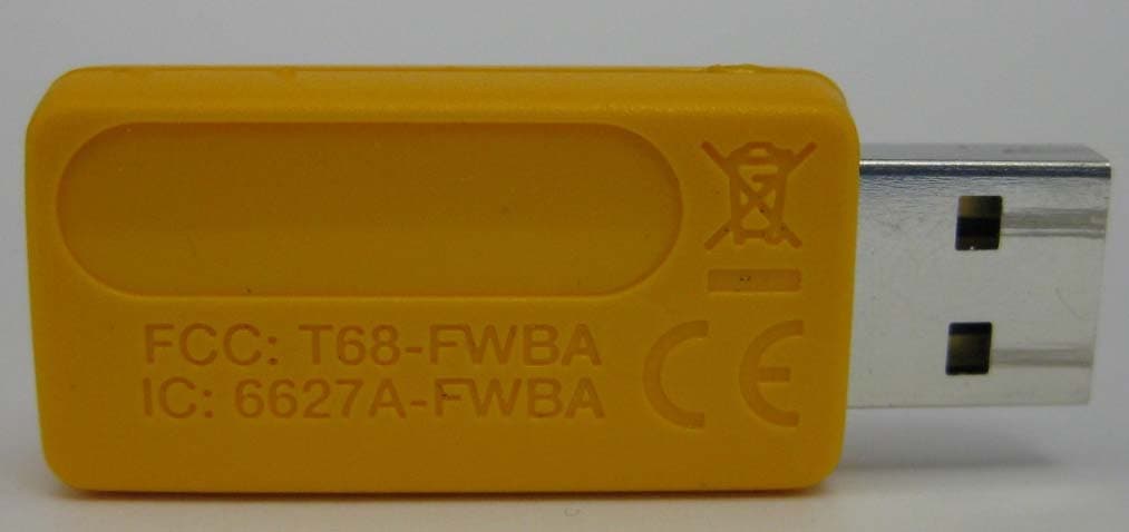
T68-FWBA
Oct 27, 2015USB1 FC WiFi-BLE Adapter
Equipment Class
DTS - Digital Transmission System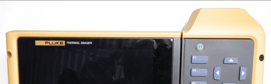
T68-FT560
May 14, 2015TiX560, TiX520
Equipment Class
DSS - Part 15 Spread Spectrum Transmitter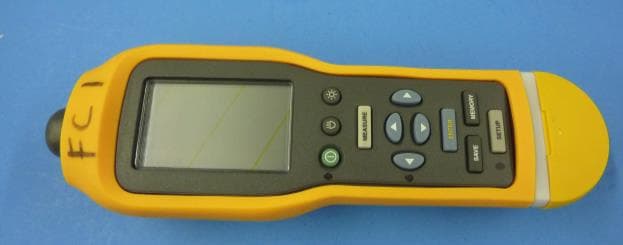
T68-805FC
May 10, 2015Vibration Meter
Equipment Class
DSS - Part 15 Spread Spectrum TransmitterT68-FBLE
Oct 27, 2013Radio Module
Equipment Class
DSS - Part 15 Spread Spectrum Transmitter
T68-FT400
Sep 29, 2013Gemini
Equipment Class
DTS - Digital Transmission System