T7V1781BLE 5 LE LR Module
Panasonic Industrial Devices Europe GmbH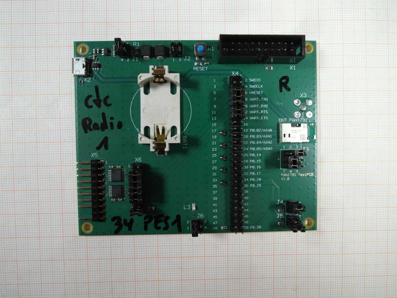
Click to zoom
Application Details
- Equipment Class
- DSS - Part 15 Spread Spectrum Transmitter
- Date of Grant
- Apr 22, 2021
- Application Purpose
- Original Equipment
- Date of Application
- Apr 22, 2021
- Equipment Note
- BLE 5 LE LR Module
- Frequency Range
- 2402.00000000 - 2480.00000000
- Country
- Germany
Documents & Files
Document Text
Text extracted from the exhibit documents filed with the FCC. Open a document above to read the original.
Users Manual
Wireless Connectivity PAN1781 Bluetooth ® Low Energy Module Module Integration Guide Rev. 0.2 PAN1781 Bluetooth Module Module Integration Guide Rev. 0.2 Page 2 of 24 Overview The PAN1781 is a Bluetooth 5 Low Energy (LE) module based on the Nordic nRF52820 single chip controller. Features • Surface mount type dimensions: 15.6 mm × 8.7 mm × 2 mm • Drop-in replacement for PAN1026A and PAN1762 • Nordic nRF52820 featuring ARM Cortex-M4 with 64 MHz • Bluetooth 5 LE including LE 2M and LE Coded PHY • Embedded 256 kB flash memory and 32 kB internal RAM • 128-bit AES/ECB/CCM/AAR co-processor • Up to 16 General Purpose I/O’s (GPIO), which are shared with up to 2× SPI, 2× I²C, UART, COMP, QDEC, nRESET • USB 2.0 full-speed device interface • Built-in temperature sensor Bluetooth • LE 2 Mbps high speed PHY, LE long range coded PHY • LE advertising extensions (advertising on 40 channels total) • Channel selection algorithm #2 • LE secure connections • Angle of arrival (AoA) and angle of departure (AoD) direction finding Characteristics • Typical sensitivity: -95 dBm at 1 Mb/s and -103 dBm at 125 kb/s • Typical max. output power: 8 dBm, configurable from -20 dBm in 4 dB steps and -40 dBm in whisper mode • Typical current consumption: 4.9 mA in Tx (at 0 dBm) and 4.7 mA in Rx mode • Typical current consumption: 0.3 μA in System OFF mode, 1.2 μA with RTC wake up • On-module DC/DC and LDO regulators with automated low current modes • Voltage range: 1.7 V to 5.5 V • Temperature range: -40 °C to 85 °C Block Diagram PAN1781 Bluetooth Module Module Integration Guide Rev. 0.2 Page 3 of 24 By purchase of any of the products described in this document the customer accepts the document's validity and declares their agreement and understanding of its contents and recommendations. Panasonic Industrial Devices Europe GmbH (Panasonic) reserves the right to make changes as required at any time without notification. Please consult the most recently issued Module Integration Guide before initiating or completing a design. © Panasonic Industrial Devices Europe GmbH 2021. This specification sheet is copyrighted. Reproduction of this document is permissible only if reproduction is without alteration and is accompanied by all associated warranties, conditions, limitations, and notices. Do not disclose it to a third party. All rights reserved. This Module Integration Guide does not lodge the claim to be complete and free of mistakes. Engineering Samples (ES) If Engineering Samples are delivered to the customer, these samples have the status “Engineering Samples”. This means that the design of this product is not yet concluded. Engineering Samples may be partially or fully functional, and they may differ from the published Product Specification. Engineering Samples are not qualified and they are not to be used for reliability testing or series production. Disclaimer The customer acknowledges that samples may deviate from the Module Integration Guide and may bear defects due to their status of development and the lack of qualification mentioned above. Panasonic rejects any liability or product warranty for Engineering Samples. In particular, Panasonic disclaims liability for damages caused by: • The use of the Engineering Sample other than for evaluation purposes, particularly the installation or integration in another product to be sold by the customer, • Deviation or lapse in function of the Engineering Sample, • Improper use of the Engineering Sample. Panasonic Industrial Devices Europe GmbH disclaims any liability for consequential and incidental damages. In case of any queries regarding the Engineering Samples, please contact your local sales partner or the related product manager. The information contained herein is presented only as guidance for Product use. No responsibility is assumed by Panasonic for any infringement of patents or any other intellectual property rights of third parties that may result from the use of Product. No license to any intellectual property right is granted by this document, whether express or implied, by estoppel or otherwise. Description of hardware, software, and other information in this document is only intended to illustrate the functionality of the referred Panasonic product. It should not be construed as guaranteeing specific functionality of the product as described or suitable for a particular application. Any provided (source) code shall not be used or incorporated into any products or systems whose manufacture, use or sale is prohibited under any applicable laws or regulations. Any outlined or referenced (source) code within this document is provided on an “as is” basis without any right to technical support or updates and without warranty of any kind on a free of charge basis according to § 516 German Civil Law (BGB) including without limitation, any warranties or conditions of title, non infringement, merchantability, or fitness for a particular purpose. Customer acknowledges that (source) code may bear defects and errors. PAN1781 Bluetooth Module Module Integration Guide Rev. 0.2 Page 4 of 24 The third-party tools mentioned in this document are offered by independent third-party providers who are solely responsible for these products. Panasonic has no responsibility whatsoever for the performance, product descriptions, specifications, referenced content, or any and all claims or representations of these third-party providers. Panasonic makes no warranty whatsoever, neither express nor implied, with respect to the goods, the referenced contents, or any and all claims or representations of the third-party providers. To the maximum extent allowable by Law Panasonic assumes no liability whatsoever including without limitation, indirect, consequential, special, or incidental damages or loss, including without limitation loss of profits, loss of opportunities, business interruption, and loss of data. PAN1781 Bluetooth Module Module Integration Guide Rev. 0.2 Page 5 of 24 Table…
Text truncated - open the document above for the full version.
Cover Letter(s)
CONFIDENTIALITY REQUEST for Certification Service in USA Federal Communication Commission Equipment Authorization Division, Application Processing Branch 7435 Oakland Mills Road Columbia, MD 21048 2021-04-19 TO WHOM IT MAY CONCERN Pursuant to Paragraphs §0.457 and 0.459 of the Commission’s Rules (47 C.F.R.) and Section §552(b)(4) of the Freedom of Information Act, we request confidentiality for the following products: FCC ID Number Product Title/Model T7V1781 PAN1781 For the product stated above, we request permanent confidentiality for exhibits which contain Operational Description, Block Diagram, Schematics, Parts Lists or Tune Up Information. The above exhibits contain our trade secrets and proprietary information that could be of benefit to our competitors. If you have any questions, please feel free to contact me at the address shown below. Sincerely, (signed) Name: Olaf Knoth Company: Panasonic Industrial Devices Europe GmbH Address: Zeppelinstraße 19, 21337 Lüneburg Phone: +49 4131 899 257 Email: [email protected]
Cover Letter(s)
SHORT-TERM CONFIDENTIALITY REQUEST Federal Communication Commission Equipment Authorization Division, Application Processing Branch 7435 Oakland Mills Road Columbia, MD 21048 2021-04-19 TO WHOM IT MAY CONCERN Pursuant to Paragraphs §0.457 and 0.459 of the Commission’s Rules (47 C.F.R.) and Section §552(b)(4) of the Freedom of Information Act, we requests short term confidentiality for the following product: FCC ID Number Product Title/Model T7V1781 PAN1781 For the product stated above, we request that the following information be held confidential: 1. External and Internal Photographs 2. Test Setup Photos 3. User Manual We request this confidentiality on the basis of ensuring that business sensitive information remains confidential until the actual marketing of our new device, which is planned for 2021-05-28. If you have any questions, please feel free to contact me at the address shown below. Sincerely, (signed) Name: Olaf Knoth Company: Panasonic Industrial Devices Europe GmbH Address: Zeppelinstraße 19, 21337 Lüneburg Phone: +49 4131 899 257 Email: [email protected]
Cover Letter(s)
Federal Communication Commission Equipment Authorization Division, Application Processing Branch 7435 Oakland Mills Road Columbia, MD 21048 Certification and Engineering Bureau Innovation, Science and Economic Development Canada Spectrum Engineering Branch 3701 Carling Avenue, Building 94 Ottawa, Ontario K2H 8S2 Subject: FCC / ISED Modular Approval Statement FCC ID: CN: (Company Number) UPN: (Unique Product Number) HVIN: (Hardware Version Id. Number) PMN: (Product Marketing Name) HMN: (Host Marketing Name) FVIN: ( Firmware Version Id . Number) TO WHOM IT MAY CONCERN Pursuant to Paragraphs RSP-100, Issue 12 and CFR § 15.212, we herewith declare for our module. Modular approval requirement Yes No * (a) The radio elements shall have the radio frequency circuitry shielded. Physical/discrete and tuning capacitors may be located external to the shield, but shall be on the module assembly. * Please provide a detailed explanation if the answer is “No.”: (b) If the module has modulation/data input(s), they shall be buffered in order to ensure that the module will comply with the requirements set out in the applicable Radio Standards Specification (RSS) and Part 15 under conditions of excessive data rates or over-modulation. * Please provide a detailed explanation if the answer is “No.”: (c) The module shall have its own power supply regulation on the module itself. This is to ensure that the module will comply with the requirements set out in the applicable standard regardless of the design of the power supplying circuitry in the host product that houses the module. * Please provide a detailed explanation if the answer is “No.”: (d) The module shall comply with the provisions for external power amplifiers and antennas detailed in the applicable RSS and rule part. The equipment certification application shall contain: i.a detailed description of the configuration of highest antenna gain for each type of transmitting antenna for licence-exempt modules; ii.the maximum transmitting antenna gain for licence modules; and iii. a detailed description of the configuration of lowest antenna gain for each type of receiving antenna for Dynamic Frequency Selection (DFS) modules with removable antenna(s). * Please provide a detailed explanation if the answer is “No.”: Modular Approval Attestation RSP-100, Issue 12, August 2019 Check your CN here. Check your GC here. Click Grantee Search. Grantee Code Equipment Product Cod e If you have any questions, please feel free to contact us at t he address shown below Best regards, INFO for applicant: Limited Modolar Approval (LMA) may be granted when one or more of the requirements in the table above cannot be demonstrated. LMA will also be issued in those instances where applicants can demonstrate that they will retain control over the final installation of the device, such that compliance of the end product is assured. In such cases, an operating condition on the L MA for the module must state that the module is only approved for use when installed in devices produced by a specificmanufacturer. When L MA is sought, the application for equipment certification must specifically state how control of the end product, into which the module will be in stalled, will be maintained, such that full compliance of the end product is always ensured. Company Name: Phone: Company Address: Fax: E-mail: Contact Name: Signature: Signature Date: Document Version 2.1 2020-10-30 Modular approval requirement Yes No * (e) The module shall be tested for compliance with the applicable standard in a stand-alone configuration (i.e. the module shall not be inside another product during testing). * Please provide a detailed explanation if the answer is “No.”: (f) The module complies or will comply with applicable RSS-102 exposure requirements and any applicable FCC RF exposure requirement (§§1.1307(b), 1.1310, 2.1091, and 2.1093) in its intended configuration/integration in a host. * Please provide a detailed explanation if the answer is “No.”: (g) The module must be labeled with its permanently affixed label (indicating ISED certification number, HVIN and FCC identifier), or use an electronic display (see KDB Publication 784748 and RSP-100, section 5). * Please provide a detailed explanation if the answer is “No.”: (h) The module must comply with all specific rules applicable to the transmitter, including all the conditions provided in the integration instructions by the grantee. * Please provide a detailed explanation if the answer is “No.”: (i) (Only applicable for FCC) The module must contain a permanently attached antenna, or contain a unique antenna connector, and be marketed and operated only with specific antenna(s), per §§ 15.203, 15.204(b), 15.204(c), 15.212(a), 2.929(b). For further information concerning antenna connectors see: DA-00-1087. * Please provide a detailed explanation if the answer is “No.”:
External Photos
Annex A 1-1479/20-01-01_AnnexA External photos of the Equipment Under Test This addendum is electronically signed and valid without handwritten signature. For verification of the electronic signatures, the public keys can be requested at the testing laboratory. Document authorized: Andreas Kurzkurt Testing Manager Radio Communications & EMC CTC advanced GmbHUntertuerkheimer Str. 6-10 66117 Saarbruecken / Germany Phone: +49 681 5 98 - 0 Fax: +49 681 5 98 - 9075 web: ctcadvanced.com e-mail: [email protected] Photos Photo 1 radiated Sample Photo 2 radiated Sample 2021-03-24Document No. 1-1479/20-01-01_AnnexA2/5 Photo 3 radiated Sample Photo 4 conducted Sample 2021-03-24Document No. 1-1479/20-01-01_AnnexA3/5 Photo 5 conducted Sample Photo 6 conducted Sample 2021-03-24Document No. 1-1479/20-01-01_AnnexA4/5 Document history VersionApplied changesDate of release initial release2021-03-24 - END OF DOCUMENT - 2021-03-24Document No. 1-1479/20-01-01_AnnexA5/5
ID Label/Location Info
REASONING PANASONIC BT MODUL PAN1781 WITHOUT FCC ID ON PRODUCT CAUSED BY SIZE RESTRICTIONS In KDB784748D01V09r01 chapter 3 the FCC states the following: (3) CERTIFICATION For certification, the product shall bear a nameplate or label with the FCC Identifier (FCC ID), as defined in Section 2.925.13 The FCC ID must always be accessible when using the product. The placement of the FCC ID must be a physical label on the product, unless an e-label is used. Physical FCC ID labels must be located on the surface of the product, or within a user-accessible non-detachable compartment (such as the battery compartment). The label shall be permanently affixed, permitting the device to be positively identified. The font needs to be readily legible, consistent with the dimensions of the equipment and its label area. When the device is so small, or for such use that it is impracticable to label with a font size that is four-points or larger (and the device does not utilize electronic labeling), then the FCC ID shall be placed in the user manual, and the FCC ID shall also be placed either on the device packaging or on a removable label attached to the device Definition of point (pt) A computer point (pt) is the smallest unit of measure in typography. It is a subdivision of the larger pica. The contemporary desktop publishing point (also called the PostScript point) was defined as 72 points to the inch (1 point = 1⁄72 inches = 25.4⁄72 mm = 0.3527 mm). Conversion 4pt to mm 4pt = 0.3527 x 4mm = 1,4108mm The below dimensioned and magnified graphic shows the product with the actual label and a visualized FCC ID printed in 4pt font size. It demonstrates that the FCC ID doesn’t fit on the label if printed in 4pt. The brand name, product number, lot code and 2D data matrix code are laser printed in a font smaller than 2pt and are intended to be read by machines (scanner) or in a factory using a microscope. This product is intended to be sold to OEM’s only. The OEM is obliged to print on the label of the end product containing this BT module the following This product contains transmitter FCC ID: T7V1781 Module Laser Marking Description No. Item ENW89857A1KF, ENW89857A2KF 1 Series (Brand) PAN1781 2 HW/SW Version HW Major Hardware Version: please refer to MS-CS-PAN1781 document SW Major Software Version: please refer to AI document 3 ENW-No. / Model Name ENW89857A1KF, ENW89857A2KF 4 Lotcode (YYWWDLL) YY - Year WW - Calendar Week D - Day of Week (e.g. Friday is 5) L - Line L - Lot 5 ES Marking Need to be mentioned during ES status (remove ES for MP) Necessity of ES marking will also be stated in the ECN 6 2D Data Matrix Code Contains in total 30 characters, seperated by a semicolon. YYWWDLL;HHHHHHHH;89853A1;HW(Minor Version);SW YYWWDLL Production Date Code (see No. 6 above) HHHHHHHH Last eight digits from hexadecimal Panasonic Mac Address (example: 001343ABCDEF) 89854A1 Part of the ENW-Number HW(Minor);SW(Minor) Minor Hardware and Minor Software Version, each 2 digits, please refer to MS-CS-PAN1781 and AI Document 7 Pin 1 Mark on Top Side Fix, no change at all 8 BT marking Bluetooth logo
ID Label/Location Info
https://www.pideu.de/confluence/display/STLU/MS-PL- PAN1781+ENW89857A1KF 1 von 1 18.02.2021, 09:41
ID Label/Location Info
https://www.pideu.de/confluence/display/STLU/MS-PL- PAN1781+ENW89857A2KF 1 von 1 18.02.2021, 09:39
RF Exposure Info
BNetzA - CAB - 02/21 - 102 D - P L - 1 2 0 7 6 - 0 1 - 0 3 SAR Test exclusion documentation according to FCC KDB 447498, RSS-102 Report identification number: 1-1479/20-01-09 Exclusion (FCC_ISED) contains the module with the following certification numbers FCC ID T7V1781 ISED number 216Q-1781 HVIN (Hardware Version Identification Number) ENW89857A1KF, ENW89857A2KF PMN (Product Marketing Name) PAN1781 FVIN (Firmware Version Identification Number) S113, S112, S140 HMN (Host Marketing Name) -/- This report is electronically signed and valid without handwriting signature. For verification of the electronic signatures, the public keys can be requested at the testing laboratory. Document authorised: Alexander Hnatovskiy Marco Scigliano Lab Manager Testing Manager Radio Communications & EMC Radio Communications & EMC Test report no.: 1-1479/20-01-09 © CTC advanced GmbH Page 2 of 2 EUT technologies: Technologies: Max. rated power: (AVG) Max. gain: Min. pathloss: Bluetooth LE Declared: max 6.1 dBm 2.0 dBi 0 dB (if applicable) Note: Bluetooth LE test results see CTC advanced test report 1-1479/20-01-06 Max. Peak conducted measured: 6.1dBm, Duty Cycle: 100.0% SAR test exclusion according to KDB447498 (General RF Exposure Guidance v06) Equation from Chapter 4.3.1: Standalone SAR test exclusion considerations page 11 and ff. (1) Standalone SAR test exclusion for 100 MHz to 6 GHz at test separation distances ≤ 50mm ( Threshold 1-g;10-g ) × d seperation / f 0.5 where Threshold 1-g;10-g is 3 for 1-g; 7.5 for 10-g d seperation is the min. test separation distance; 5mm is used if the distance is less f is the RF channel transmit frequency The table below gives the calculated maximal power that could be used for source based time averaged conducted or radiated power, adjusted for tune up tolerance. If this is at or below the calculated value the DUT is exempted from SAR evaluation. frequency d separation Powerlimit [MHz] [mm] [mW] [dBm] [mW] 2450.00 5 3 9.58 6.10 4.07 yes Threshold 1-g Exclusion P max-declared SAR test exclusion according to RSS-102 Issue 5 Section 2.5.1/Table 1 The table below gives the calculated maximal power that could be used for source based time averaged conducted or radiated power, adjusted for tune up tolerance. If this is at or below the calculated value the DUT is exempted from SAR evaluation. frequency d separation Powerlimit [MHz] [mm] [mW] [dBm] [mW] 2450.00 10 1 g 7.00 8.10 6.46 yes tissue volume P max-declared Exclusion The limits above are defined for body worn application and therefore cover all use cases.
Test Report
Measurement Results No.1-1479/20-01-06_Annex_MR_A1 Test logging This document is electronically signed and valid without handwritten signature. For verification of the electronic signatures, the public keys can be requested at the testing laboratory. Test/s performed: Jörg Warken Lab Manager Radio Communications & EMC CTC advanced GmbHUntertuerkheimer Str. 6-10 66117 Saarbruecken / Germany Phone: +49 681 5 98 - 0 Fax: +49 681 5 98 - 9075 web: ctcadvanced.com e-mail: [email protected] Table of Content EUT Information3 Common2G4 Peak OP 3MHz/3MHz4 FCC Part 15.247 Maximum Peak Conducted Output Power DTS8 FCC Part 15.247 Bandwidth 6dB DTS15 FCC Part 15.247 Peak Power Spectral Density DTS19 FCC Part 15.247 Bandwidth 99PCT-20dB23 FCC Part 15.247 TX Spurious Conduced33 FCC Part 15.247 Restricted Band Edge Conducted Peak DTS Video Avg40 Common2G4 Peak OP 3MHz/3MHz44 FCC Part 15.247 Maximum Peak Conducted Output Power DTS48 FCC Part 15.247 Bandwidth 6dB DTS55 FCC Part 15.247 Peak Power Spectral Density DTS59 FCC Part 15.247 Bandwidth 99PCT-20dB63 FCC Part 15.247 TX Spurious Conduced73 FCC Part 15.247 Restricted Band Edge Conducted Peak DTS Video Avg80 FCC Part 15.247 Peak Power Spectral Density DTS84 FCC Part 15.247 Maximum Peak Conducted Output Power DTS88 FCC Part 15.247 Peak Power Spectral Density DTS95 FCC Part 15.247 Maximum Peak Conducted Output Power DTS99 2021-03-11Document 1-1479/20-01-06_Annex_MR_A12/105 EUT Information EUT DEFINITION ManufacturerPanasonic Industrial Devices Europe GmbH TypePAN1781 Serial Number | Setup Numberctc Radio 2 | 1.0 Version SW | FW | HWNI | S130, S140 | V1 Comment 1 | 2 | Temperature [°C] Min | Nom | Max -40 | 20 | 85 Voltage [V] Min | Nom | Max @Current Max [A] 3.3 | 3 | 5.5 1.7 2021-03-11Document 1-1479/20-01-06_Annex_MR_A13/105 Common2G4 Peak OP 3MHz/3MHz Test References TC Start08.03.2021 15:21:07 Ambit Temp [°C] | Humidity [rel%] 23.1 | 17 System Version2.0.0.4 Test SpecificationNone Test Method TC Version0.0.1 My DescriptionPeak Output Power conducted 3MHz/3MHz - BT LE 1 Msps Add. Information EUT Common Settings BT Low Energy Intermodulation Value N 3 Image Freq. Low | Mid | High [MHz] 0 | 0 | 0 Power Class2 1 Mbps supported True | TXpayload 255 | RXpayload 255 2 Mbps supported True | TXpayload 255 | RXpayload 255 Longrange S8 supported True | TXpayload 255 | RXpayload 255 Longrange S2 supportedTrue | TXpayload 255 | RXpayload 255 Signaling Settings WS_USB_RS232 | TWO | 13 | 19200 | None | S1 | None | On Signaling RF Settings RF1com | 0 | 0 | On | User Interaction No Switch Matrix & Pathcompensation enabled Yes Test Parameter Technology to testBT LE 1 Msps Antenna Port used1 Temperaturenom Voltagenom Frequency low to testTrue | Freq [MHz] 2402 Frequency mid to testTrue | Freq [MHz] 2440 Frequency high to testTrue | Freq [MHz] 2480 Auto Control enabled Power Supply | Climatic Box No | No Additional Path Loss [dB]0 Switched PathEUT - SignalingUnit - SpectrumAnalyzer Devices in useSigBT: Rohde&Schwarz,CMW,1201.0002k75/100683,3.7.171 | SA: Rohde&Schwarz,FSV-30,1321.3008K30/103809,3.70 2021-03-11Document 1-1479/20-01-06_Annex_MR_A14/105 Test at TX 2402 MHz RESULT: Reference Power cond. Test DescriptionLower LimitUpper LimitMeasuredUnitVerdict Ref. Power 1MHz/1MHz cond. ------5.72dBmINFO Ref. Frequency------2401.800MHzINFO READ SA SETTINGS: RefLevel [dBm] | RefLevelOffset [dB] | InpAtt [dB]15.72 | 10.09 | 25 Start [MHz] | Stop [MHz]2399.500 | 2404.500 RBW [MHz] | VBW [MHz]3.000000 | 3.000000 Detector | TraceModePOS | MAXH Sweep: Time [ms] | Count | Points per Section | Type1000 | 10 | 1001 | SWE RESULT Test DescriptionLower LimitUpper LimitMeasuredUnitVerdict Peak Power------5.53dBmInfo Peak Power------3.572728mWInfo Frequency at Peak------2402.24MHzInfo Common2G4 Peak OP 3MHz-3MHz ~ BT LE 1 Msps 2021-03-11Document 1-1479/20-01-06_Annex_MR_A15/105 Test at TX 2440 MHz RESULT: Reference Power cond. Test DescriptionLower LimitUpper LimitMeasuredUnitVerdict Ref. Power 1MHz/1MHz cond. ------5.64dBmINFO Ref. Frequency------2439.800MHzINFO READ SA SETTINGS: RefLevel [dBm] | RefLevelOffset [dB] | InpAtt [dB]15.64 | 10.1 | 25 Start [MHz] | Stop [MHz]2437.500 | 2442.500 RBW [MHz] | VBW [MHz]3.000000 | 3.000000 Detector | TraceModePOS | MAXH Sweep: Time [ms] | Count | Points per Section | Type1000 | 10 | 1001 | SWE RESULT Test DescriptionLower LimitUpper LimitMeasuredUnitVerdict Peak Power------5.49dBmInfo Peak Power------3.539973mWInfo Frequency at Peak------2439.78MHzInfo Common2G4 Peak OP 3MHz-3MHz ~ BT LE 1 Msps 2021-03-11Document 1-1479/20-01-06_Annex_MR_A16/105 Test at TX 2480 MHz RESULT: Reference Power cond. Test DescriptionLower LimitUpper LimitMeasuredUnitVerdict Ref. Power 1MHz/1MHz cond. ------6.16dBmINFO Ref. Frequency------2479.800MHzINFO READ SA SETTINGS: RefLevel [dBm] | RefLevelOffset [dB] | InpAtt [dB]16.16 | 10.15 | 25 Start [MHz] | Stop [MHz]2477.500 | 2482.500 RBW [MHz] | VBW [MHz]3.000000 | 3.000000 Detector | TraceModePOS | MAXH Sweep: Time [ms] | Count | Points per Section | Type1000 | 10 | 1001 | SWE RESULT Test DescriptionLower LimitUpper LimitMeasuredUnitVerdict Peak Power------6.09dBmInfo Peak Power------4.064433mWInfo Frequency at Peak------2479.74MHzInfo Common2G4 Peak OP 3MHz-3MHz ~ BT LE 1 Msps 2021-03-11Document 1-1479/20-01-06_Annex_MR_A17/105 FCC Part 15.247 Maximum Peak Conducted Output Power DTS Test References TC Start08.03.2021 15:22:37 Ambit Temp [°C] | Humidity [rel%] 23.1 | 18 System Version2.0.0.4 Test SpecificationFCC Part 15.247 Test MethodDTS: KDB 558074 D01 V05 - Chapter 8.3.1.1 RBW ≥ DTS Bandwidth TC Version0.0.1 My DescriptionFCC 15.247 Maximum Peak Output Power Conducted DTS - BT LE 1 Msps Add. Information EUT Common Settings BT Low Energy Intermodulation Value N 3 Image Freq. Low | Mid | High [MHz] 0 | 0 | 0 Power Class2 1 Mbps supported True | TXpayload 255 | RXpayload 255 2 Mbps supported True | TXpayload 255 | RXpayload 255 Longrange S8 supported True | TXpayload 255 | RXpayload 255 Longrange S2 supportedTrue | TX…
Text truncated - open the document above for the full version.
Test Report
Test at TX 2402 MHz RESULT: Reference Power cond. Test DescriptionLower LimitUpper LimitMeasuredUnitVerdict Ref. Power 1MHz/1MHz cond. ------5.68dBmINFO Ref. Frequency------2401.700MHzINFO READ SA SETTINGS: RefLevel [dBm] | RefLevelOffset [dB] | InpAtt [dB]10.68 | 10.09 | 20 Start [MHz] | Stop [MHz]2401.000 | 2403.000 RBW [MHz] | VBW [MHz]0.100000 | 0.300000 Detector | TraceModePOS | MAXH Sweep: Time [ms] | Count | Points per Section | Type50 | 200 | 10001 | SWE DTS Bandwidth Test DescriptionLower LimitUpper LimitMeasuredUnitVerdict DTS Bandwidth (6dB) ------699kHzINFO FCC Part 15.247 Maximum Peak Conducted Output Power DTS ~ BT LE coded S2 DTS BW READ SA SETTINGS: RefLevel [dBm] | RefLevelOffset [dB] | InpAtt [dB]15.68 | 10.09 | 25 Start [MHz] | Stop [MHz]2401.000 | 2403.000 RBW [MHz] | VBW [MHz]1.000000 | 5.000000 Detector | TraceModePOS | MAXH Sweep: Time [ms] | Count | Points per Section | Type50 | 200 | 1001 | SWE RESULT Test DescriptionLower LimitUpper LimitMeasuredUnitVerdict Peak Power---30.005.32dBmPASS Peak Power---10003.404082mWPASS Frequency at Peak------2402.26MHzINFO 2021-03-11Document 1-1479/20-01-06_Annex_MR_A189/105 FCC Part 15.247 Maximum Peak Conducted Output Power DTS ~ BT LE coded S2 2021-03-11Document 1-1479/20-01-06_Annex_MR_A190/105 Test at TX 2440 MHz RESULT: Reference Power cond. Test DescriptionLower LimitUpper LimitMeasuredUnitVerdict Ref. Power 1MHz/1MHz cond. ------5.71dBmINFO Ref. Frequency------2439.800MHzINFO READ SA SETTINGS: RefLevel [dBm] | RefLevelOffset [dB] | InpAtt [dB]10.71 | 10.1 | 20 Start [MHz] | Stop [MHz]2439.000 | 2441.000 RBW [MHz] | VBW [MHz]0.100000 | 0.300000 Detector | TraceModePOS | MAXH Sweep: Time [ms] | Count | Points per Section | Type50 | 200 | 10001 | SWE DTS Bandwidth Test DescriptionLower LimitUpper LimitMeasuredUnitVerdict DTS Bandwidth (6dB) ------694kHzINFO FCC Part 15.247 Maximum Peak Conducted Output Power DTS ~ BT LE coded S2 DTS BW READ SA SETTINGS: RefLevel [dBm] | RefLevelOffset [dB] | InpAtt [dB]15.71 | 10.1 | 25 Start [MHz] | Stop [MHz]2439.000 | 2441.000 RBW [MHz] | VBW [MHz]1.000000 | 5.000000 Detector | TraceModePOS | MAXH Sweep: Time [ms] | Count | Points per Section | Type50 | 200 | 1001 | SWE RESULT Test DescriptionLower LimitUpper LimitMeasuredUnitVerdict Peak Power---30.005.4dBmPASS Peak Power---10003.467369mWPASS Frequency at Peak------2439.746MHzINFO 2021-03-11Document 1-1479/20-01-06_Annex_MR_A191/105 FCC Part 15.247 Maximum Peak Conducted Output Power DTS ~ BT LE coded S2 2021-03-11Document 1-1479/20-01-06_Annex_MR_A192/105 Test at TX 2480 MHz RESULT: Reference Power cond. Test DescriptionLower LimitUpper LimitMeasuredUnitVerdict Ref. Power 1MHz/1MHz cond. ------6.28dBmINFO Ref. Frequency------2479.800MHzINFO READ SA SETTINGS: RefLevel [dBm] | RefLevelOffset [dB] | InpAtt [dB]11.28 | 10.15 | 20 Start [MHz] | Stop [MHz]2479.000 | 2481.000 RBW [MHz] | VBW [MHz]0.100000 | 0.300000 Detector | TraceModePOS | MAXH Sweep: Time [ms] | Count | Points per Section | Type50 | 200 | 10001 | SWE DTS Bandwidth Test DescriptionLower LimitUpper LimitMeasuredUnitVerdict DTS Bandwidth (6dB) ------703kHzINFO FCC Part 15.247 Maximum Peak Conducted Output Power DTS ~ BT LE coded S2 DTS BW READ SA SETTINGS: RefLevel [dBm] | RefLevelOffset [dB] | InpAtt [dB]16.28 | 10.15 | 25 Start [MHz] | Stop [MHz]2479.000 | 2481.000 RBW [MHz] | VBW [MHz]1.000000 | 5.000000 Detector | TraceModePOS | MAXH Sweep: Time [ms] | Count | Points per Section | Type50 | 200 | 1001 | SWE RESULT Test DescriptionLower LimitUpper LimitMeasuredUnitVerdict Peak Power---30.006.07dBmPASS Peak Power---10004.045759mWPASS Frequency at Peak------2479.75MHzINFO 2021-03-11Document 1-1479/20-01-06_Annex_MR_A193/105 FCC Part 15.247 Maximum Peak Conducted Output Power DTS ~ BT LE coded S2 2021-03-11Document 1-1479/20-01-06_Annex_MR_A194/105 FCC Part 15.247 Peak Power Spectral Density DTS Test References TC Start09.03.2021 16:52:13 Ambit Temp [°C] | Humidity [rel%] 22.8 | 22 System Version2.0.0.4 Test SpecificationFCC Part 15.247 Test MethodDTS: KDB 558074 D01 V05 - Chapter 8.4 DTS maximum power spectral density level in the …
Text truncated - open the document above for the full version.
Contact Information
Applicant
Olaf Knoth(Product Safety)
Test Firm
cetecom advanced GmbHGerald Schmidt
Technical Specifications
| # | Rule Parts | Frequency Range | Power Output |
|---|---|---|---|
| 1 | 15C | 2.40 GHz - 2.48 GHz | 4.07 mW |
Other Applications from Panasonic Industrial Devices Europe GmbH
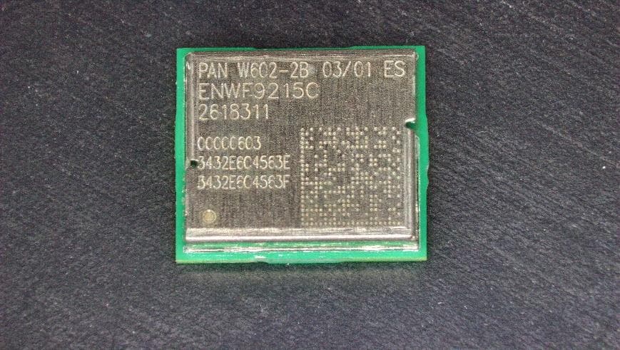
T7V-W602
Jul 14, 2026WiFi / BLE Module
Equipment Class
NII - Unlicensed National Information Infrastructure TX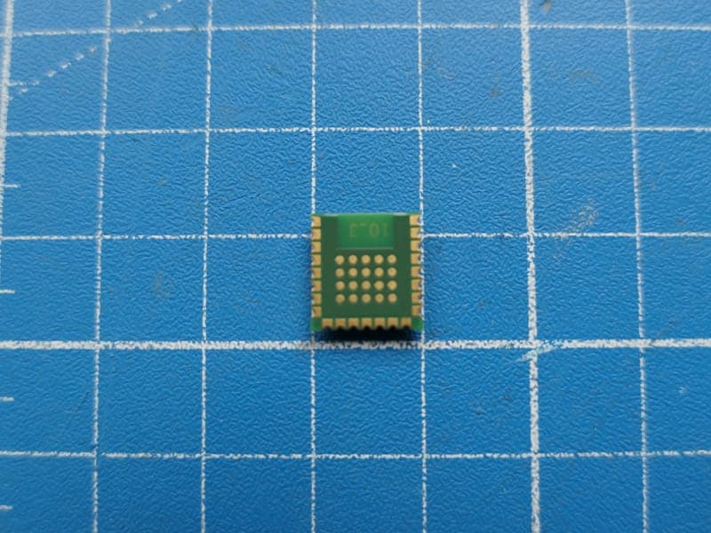
T7V-B611
Dec 19, 2025Bluetooth LE LR Module
Equipment Class
DTS - Digital Transmission System
T7V9019
Apr 18, 2024Wi-Fi 6 Dual Band 2.4 GHz/5 GHz, Bluetooth and 802.15.4 Module
Equipment Class
NII - Unlicensed National Information Infrastructure TX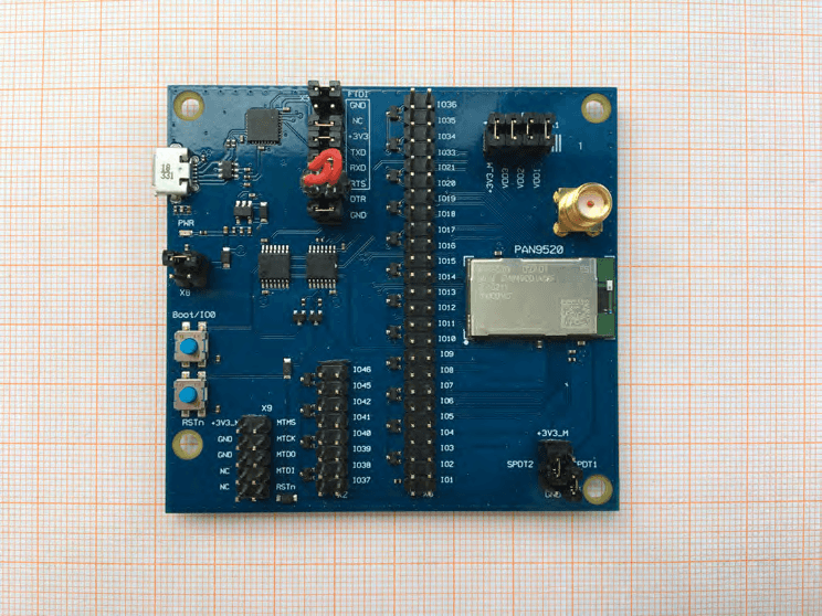
T7V9520
May 31, 2021Wi-Fi Module
Equipment Class
DTS - Digital Transmission System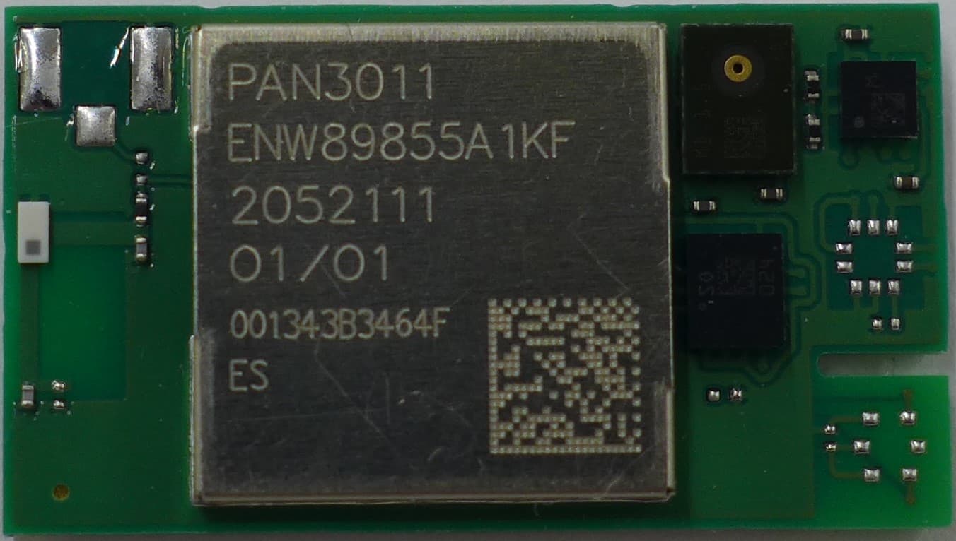
T7V301X
Apr 28, 2021Bluetooth Low Energy Module
Equipment Class
DTS - Digital Transmission System