T8VCZ106Immobilizer
ASAHI DENSO CO.,LTD.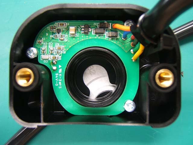
Click to zoom
Application Details
- Equipment Class
- DCD - Part 15 Low Power Transmitter Below 1705 kHz
- Date of Grant
- Feb 18, 2008
- Application Purpose
- Original Equipment
- Date of Application
- Feb 18, 2008
- Equipment Note
- Immobilizer
- Frequency Range
- 0.13420000 - 0.13420000
- Company
- ASAHI DENSO CO.,LTD.
- Country
- Japan
Documents & Files
Document Text
Text extracted from the exhibit documents filed with the FCC. Open a document above to read the original.
Users Manual
For USA and Canada (FCC/IC) FCC WARNING Changes or modifications not expressly approved by the party responsible for compliance could void the user’s authority to operate the equipment. This device complies with Part 15 of the FCC Rules and RSS-Gen of IC Rules. Operation is subject to the following two conditions: (1) this device may not cause harmful interference, and (2) this device must accept any interference received, including interference that may cause undesired operation.
External Photos
External Photo ASAHIDENSO CO., LTD. Immobilizer (Model: CZ106) FCC ID: T8VCZ106 IC Number: 6505A- CZ106
Test Report
FCC ID : T8VCZ106 Test report No. : 27HE0382-YK-A Page : 2 of 17 Issued date : February 6, 2008 UL Japan, Inc. YAMAKITA EMC LAB. 907 Kawanishi, Yamakita-machi, Ashigarakami-gun, Kanagawa-ken, 258-0124 JAPAN Telephone: +81 465 77 1011 Facsimile: +81 465 77 2112 MF060b (09.01.08) Table of Contents Page 1 Applicant Information 3 2 Equipment under test (E.U.T.) 3 3 Test Specification, Procedures and Results 4 4 System Test Configuration 6 5 Radiated Emissions (Fundamental and Spurious) 7 6 26dB Bandwidth & Occupied Bandwidth (99%) 8 Contents of Appendixes 9 APPENDIX 1: Photographs of test setup 10 APPENDIX 2: Test Data 12 APPENDIX 3: Test instruments 17 FCC ID : T8VCZ106 Test report No. : 27HE0382-YK-A Page : 3 of 17 Issued date : February 6, 2008 UL Japan, Inc. YAMAKITA EMC LAB. 907 Kawanishi, Yamakita-machi, Ashigarakami-gun, Kanagawa-ken, 258-0124 JAPAN Telephone: +81 465 77 1011 Facsimile: +81 465 77 2112 MF060b (09.01.08) 1 Applicant Information Company Name : ASAHI DENSO CO., LTD. Brand Name AD Address : 1126 Nakajo, Hamamatsu-shi, Shizuoka-ken, 434-0043 Japan Telephone Number : +81-53-587-2195 Facsimile Number : +81-53-584-1589 Contact Person : Akihiko Tsuchikiri 2 Equipment under test (E.U.T.) 2.1 Identification of E.U.T. Type of Equipment : Antenna for Immobilizer system Model No. : CZ106 Serial No. : 7Y09 Rating : DC12.0V Country of Manufacture : Japan Receipt Date of Sample : November 13, 2007 Condition of EUT : Engineering prototype (Not for Sale: This sample is equivalent to mass-produced items.) Modification of EUT : No modification by the test lab. 2.2 Product Description Model: CZ106 is an Antenna for Immobilizer system. Equipment type : Transceiver Frequency of operation : 134.2 kHz Clock frequency : 16MHz Type of modulation : ASK Antenna type : Coil Antenna connector type : Soldering ITU code : A1N Operation temperature range : -20 ~ +80 deg. C. *FCC Part 15.31 (e) The module is provided stable power supply (DC 5V), and the power is not changed when voltage of the main unit is varied. Therefore, the equipment complies power supply regulation. *FCC Part 15.203 It is impossible for end users to replace the antenna, because the antenna is mounted inside of the vehicle. Therefore, the equipment complies with the requirement. FCC ID : T8VCZ106 Test report No. : 27HE0382-YK-A Page : 4 of 17 Issued date : February 6, 2008 UL Japan, Inc. YAMAKITA EMC LAB. 907 Kawanishi, Yamakita-machi, Ashigarakami-gun, Kanagawa-ken, 258-0124 JAPAN Telephone: +81 465 77 1011 Facsimile: +81 465 77 2112 MF060b (09.01.08) 3 Test Specification, Procedures and Results 3.1 Test specification Test specification : FCC Part15 Subpart C: 2007, final revised on November 13, 2007 Title : FCC 47CFR Part15 Radio Frequency Device Subpart C Intentional Radiators Section 15.207: Conducted limits Section 15.209: Radiated emission limits, general requirements 3.2 Procedures & Results Item Test Procedure Specification Remarks DeviationWorst Margin Results Conducted Emission ANSI C63.4: 2003 7. AC powerline conducted emission measurements FCC Section 15.207 - N/A *1) N/A N/A Electric Field Strength of Fundamental Emission ANSI C63.4: 2003 13. Measurement of intentional radiators FCC Section 15.209 Radiated N/A 33.9dB (Horizontal) Complied Electric Field Strength of Spurious Emission ANSI C63.4: 2003 13. Measurement of intentional radiators FCC Section 15.209 Radiated N/A 9.5dB (212.50MHz, Horizontal) Complied 26dB Bandwidth ANSI C63.4: 2003 13. Measurement of intentional radiators - Radiated N/A - Complied *1) The test is not applicable since the EUT has no AC mains. Note: UL Japan’s EMI Work Procedures No.QPM05 and QPM15. 3.3 Addition to standard Item Test Procedure Specification Remarks Worst Margin Results Occupied Bandwidth (99%) ANSI C63.4:2003 13. Measurement of intentional radiators RSS-Gen 4.6.1 RSS-Gen 4.6.1 Radiated - Complied * Other than mentioned above, no addition, exclusion nor deviation has been made from the standard. FCC ID : T8VCZ106 Test report No. : 27HE0382-YK-A Page : 5 of 17 Issued date : February 6, 2008 UL Japan, Inc. YAMAKITA EMC LAB. 907 Kawanishi, Yamakita-machi, Ashigarakami-gun, Kanagawa-ken, 258-0124 JAPAN Telephone: +81 465 77 1011 Facsimile: +81 465 77 2112 MF060b (09.01.08) 3.4 Uncertainty The following uncertainties have been calculated to provide a confidence level of 95% using a coverage factor k=2. No.1 open site ( ± ) No.2 open site ( ± ) No.1 anechoic chamber ( ± ) Radiated emission (3m) <30MHz 2.3 dB 2.3 dB 2.2 dB 30-300MHz 4.5 dB 4.4 dB 4.5 dB 300-1000MHz 4.3 dB 4.3 dB 4.3 dB Radiated Emission Test The data listed in this test report has enough margin, more than site margin. 3.5 Test Location UL Japan, Inc. Yamakita EMC Lab. 907, Kawanishi, Yamakita-machi, Ashigarakami-gun, Kanagawa-ken 258-0124 JAPAN Telephone number : +81 465 77 1011 Facsimile number : +81 465 77 2112 NVLAP Lab. code : 200441-0 No. 1 test site has been fully described in a report submitted to FCC office, and accepted on August 26, 2005 (Registration No.: 95486). IC Registration No. : 2973B-1 No. 2 test site has been fully described in a report submitted to FCC office, and accepted on April 4, 2005 (Registration No.: 466226). IC Registration No. : 2973B-3 No. 1 anechoic chamber has been fully described in a report submitted to FCC office, and accepted on November 2, 2005 (Registration No.: 95967). IC Registration No. : 2973B-2 Test room Width x Depth x Height (m) Test room Width x Depth x Height (m) No.1 shielded room 8.0 x 5.0 x 2.5 10.0 x 7.5 x 5.7 No.2 shielded room 5.0 x 4.0 x 2.5 No.1 Semi-anechoic chamber No.3 shielded room 4.0 x 5.0 x 2.7 Open test site Maximum measurement distance No.1 open test site 30m No.2 open test site 10m 3.6 Test Setup, Data of EMI & Test instruments Refer to Appendix 1 to 3. FCC ID : T8VCZ106 Test report No. : 27HE0382-YK-A Page : 6 of 17 Issued date : February 6, 2008 UL Japan, Inc. YAMAKITA EMC LAB. 907 Kawanishi, Yamakita-machi, Ashigarakami-gun, Kanagawa-ken, 258-0124 JAPA…
Text truncated - open the document above for the full version.
Test Setup Photos
FCC ID : T8VCZ106 Test report No. : 27HE0382-YK-A Page : 10 of 17 Issued date : February 6, 2008 UL Japan, Inc. YAMAKITA EMC LAB. 907 Kawanishi, Yamakita-machi, Ashigarakami-gun, Kanagawa-ken, 258-0124 JAPAN Telephone: +81 465 77 1011 Facsimile: +81 465 77 2112 MF060b (09.01.08) Radiated emission 9kHz-30MHz 30-1000MHz Rear view Front view Front view FCC ID : T8VCZ106 Test report No. : 27HE0382-YK-A Page : 11 of 17 Issued date : February 6, 2008 UL Japan, Inc. YAMAKITA EMC LAB. 907 Kawanishi, Yamakita-machi, Ashigarakami-gun, Kanagawa-ken, 258-0124 JAPAN Telephone: +81 465 77 1011 Facsimile: +81 465 77 2112 MF060b (09.01.08) Pre-check of the worst position Below 30MHz Above 30MHz Horizontal Y Y Vertical Y Y X-axis Y-axis Z-axis
Contact Information
Applicant
TOMOHIRO YAGUCHI(MANAGER)
Technical Contact
UL Japan, IncToyokazu Imamura
[email protected]81-465-77-1011
907 Kawanishi, Yamakita-machi · Ashigarakami-gun, Kanagawa-ken · Japan
Non-Technical Contact
UL Japan IncKeijiro Kumagai
[email protected]81-596-24-8116
Test Firm
UL Japan IncOsamu Watatani
Technical Specifications
| # | Rule Parts | Frequency Range | Power Output |
|---|---|---|---|
| 1 | 15C | 0.1342 MHz - 0.1342 MHz | - |
Other Applications from ASAHI DENSO CO.,LTD.
T8VSZ137
Aug 07, 2026Immobilizer
Equipment Class
DCD - Part 15 Low Power Transmitter Below 1705 kHz
T8VZKM017A
Nov 17, 2025IGNITION SW
Equipment Class
DCD - Part 15 Low Power Transmitter Below 1705 kHz
T8VCZ186
Mar 24, 2024PANEL SW
Equipment Class
DCD - Part 15 Low Power Transmitter Below 1705 kHz
T8VZKM013A
Dec 22, 2020IGNITION SW
Equipment Class
DCD - Part 15 Low Power Transmitter Below 1705 kHz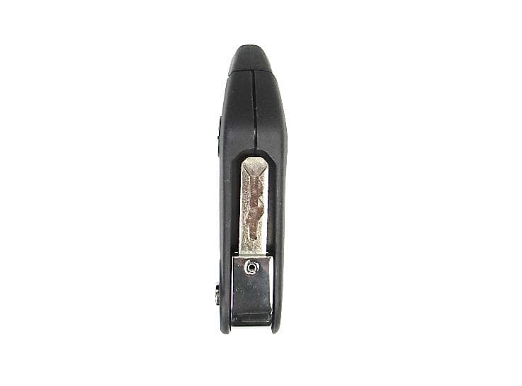
T8VZKM013A903
Dec 21, 2020SMART KEY
Equipment Class
DSC - Part 15 Security/Remote Control Transmitter