TCJ-M4BBDAUPower Amplifier
Canam Technology, Inc
Click to zoom
Application Details
- Equipment Class
- AMP - Amplifier
- Date of Grant
- Feb 13, 2006
- Application Purpose
- Original Equipment
- Date of Application
- Feb 13, 2006
- Equipment Note
- Power Amplifier
- Frequency Range
- 421.00000000 - 512.00000000
- Company
- Canam Technology, Inc
- Country
- United States
Documents & Files
Document Text
Text extracted from the exhibit documents filed with the FCC. Open a document above to read the original.
Users Manual
CANAM TECHNOLOGY, Inc. MARK-IV BROADBAND AMPLIFIERS USER’S MANUAL REVISION 3 Jan 2006 MARK-IV BROADBAND AMPLIFIERS User’s Manual 2 / 11 REV3 01/25/06 T T A A B B L L E E O O F F C C O O N N T T E E N N T T S S Section A. Introduction ...................................................................................... 3 Section B. GLOSSARY OF TERMS ....................................................................... 5 Section C. THEORY OF OPERATION .................................................................. 6 Section D. SPECIFICATIONS ............................................................................... 7 Section E. INSTALLATION.................................................................................... 8 E.1 Equipment Installation ............................................................................ 8 E.2 Antenna Installation..............................................................................10 MARK-IV BROADBAND AMPLIFIERS User’s Manual 3 / 11 REV3 01/25/06 Section A. Introduction This document is the MARK-IV Broadband Amplifiers User’s Manual, intended for the Radio Technical Personnel. The Mark-IV Broadband Amplifiers are highly-linear devices suitable for applications in the two-way radio and cellular UHF and 800 MHz bands. They are intended for use in low to mid power amplification and re-amplification systems, including land-mobile radio and cellular uni- and bi-directional signal booster systems. These amplifiers utilize linear LDMOS power devices that provide high gain, wide dynamic range, and excellent group delay and phase linearity. Exceptional performance, long term reliability, and high efficiency are achieved by employing advanced matching networks and combining techniques, EMI/RFI filters, machined housings, and qualified components. Models: UHF band: M4-BBDA-U, FCC ID: TCJ-M4BBDAU 800 MHz band: M4-BBDA-8, FCC ID: TCJ-M4BBDA8 Key Features: • Solid-state, ultra-linear design • High reliability and ruggedness. • Built-in high dynamic range with Automatic Level Control (ALC) circuit. • Built-in Output Circulator • Built-in monitoring circuits, DC signal at interface connector: o Forward Power Detector o Reverse Power Detector MARK-IV BROADBAND AMPLIFIERS User’s Manual 4 / 11 REV3 01/25/06 General Disclaimers This manual is intended to be used with the MARK-IV Equipment only. It is not to be used with any other equipment unless it is authorized by Canam Technology, Inc. Canam Technology, Inc provide this document “as is” without any warranty of any kind. This document may contain typographical errors and technical inaccuracies. Canam Technology will not accept any liability from the use and misuse of this manual, the information contained within, or the consequences of any actions resulting from the use of this information. The user can not make any modifications to the unit(s). Changes or modifications not expressly approved by the party responsible for compliance voids the user’s authority to operate the equipment. Radio-Frequency Amplifiers such as the MARK-IV generate radio signals and, therefore, electromagnetic fields. The technical personnel should have a complete understanding of FCC CFR Title 47 sections 1.1307 and 1.1310. Recommendations are included in this Manual, but they do not substitute the FCC guidelines. This device may require the use of antennas for proper functioning, depending on the application. The installation of the antennas should be performed by qualified technical personnel. All antennas should be fixed mounted and physically secured to one location. The people must be away from the antennas at least 1.0 meters to comply with the RF Human Maximum Permissible Exposure limits, as long as the antenna system gain is lower than 0 dBi. If greater gain is used the separation should be increased, please refer to the FCC Rules. If service should be performed on the antenna, please shut down the transmitter or lower its power in order to comply with the maximum permissible exposure. MARK-IV BROADBAND AMPLIFIERS User’s Manual 5 / 11 REV3 01/25/06 Section B. GLOSSARY OF TERMS AC: Alternating Current. Broadband Amplifier: A device at a fixed location which automatically receives, amplifies, and retransmits the signals received from base, fixed, mobile, and portable stations, with no change in frequency or authorized bandwidth. All signals within the passband of the amplifier filter are amplified. DC: Direct Current. Rx: Receiver or Input Port. Tx: Transmitter or Output Port. MARK-IV BROADBAND AMPLIFIERS User’s Manual 6 / 11 REV3 01/25/06 Section C. THEORY OF OPERATION The MARK-IV BROADBAND AMPLIFIERS are self contained modules having the RF Input and Output ports via SMA-type coaxial connectors and DC plus Control signals via D- Subminiature 9-pin connector. These amplifiers modules must be installed on appropriate heat-sinks to dissipate the heat they generate during normal operation (with or without input signal). It is recommendable the Case Temperature not to exceed 50 degrees Celsius to benefit the amplifier’s life span. The RF Input signal is amplified by the amplifier’s gain and delivered at the RF Output without changes in frequency, modulation or occupied bandwidth. Pout = Pin + Gain The MARK-IV BROADBAND AMPLIFIERS are equipped with Automatic Level Control (ALC) circuitry to limit the output power to the factory preset level, preventing that an input drive signal level plus the amplifier’s gain would exceed the maximum authorized output power level. In that case, the ALC circuit will proportionally decrease the gain as required not to exceed the preset output level. A red LED on the side of the amplifier’s case is lit when the ALC circuit is in operation. The amplifiers are also equipped with Input Overdrive Protection (passive “fuse-type”) to prevent further damage of its internal stages in case of accidental very strong signals well above the maximum input level required for normal operation. The MARK-IV…
Text truncated - open the document above for the full version.
Cover Letter(s)
1 Chris Harvey From:Claire Hoque [[email protected]] Sent:Monday, February 06, 2006 6:26 PM To: [email protected]; Chris Harvey Cc:Julia Luke; Thu Chan; Michael Heckrotte Subject:answer: Canam Technology, Inc, FCC ID: TCJ-M4BBDAU, Assessment NO.: AN06T5424, Notice#1 MARK-IV Broadband Amplifiers U... Confidentialityletter s 2-03-06... Hi Chris, Here are the answers. 1. The Confidentiality Letter requests that the internal photos be held from public inspection. Please note that the FCC does not generally allow internal photographs to be held confidential unless a strong justification is provided as to how the internal components would never be visible by the public (i.e. the device is not offered for sale to the public, is behind locked cabinets, etc.). Please provide a revised confidentiality letter to include either a stronger justification for the internal photographs to be withheld from public inspection or remove the internal photos from the list. <answer>pls see revised confi. letter. 2. The testing of this power amplifier was performed using an FM modulated signal (Emission Type F1D per the Form 731). The Users Manual states that these units are "suitable for several applications and modulations formats such as CDMA, GSM, TDMA, TETRA, SMR, iDEN, CW and other applications." The FCC policy is that the modulation types for which an amplifier is intended shall be used during testing. Please either update the manual to include only the FM modulation as tested, or include test data to include the other modulation types as documented in the manual. <answer>pls see updated user manual. 3. Please confirm that this amplifier is designed and will be used with only one carrier at a time. Multi-carrier capability is required to be tested for intermodulation spurious emissions per FCC policy, which has not been documented in the test report. <answer>This amplifier is designed and will be used with only one carrier at a time. 4. The Users Manual has an RF Exposure separation statement that has no supporting documentation for the stated separation distance. Please provide an MPE calculation that would justify the statement in the manual. <answer>MPE is not needed, since it is a Power Amplifier and there is no antenna. Thanks, Claire -----Original Message----- From: Compliance Certification Services [mailto:[email protected]] Sent: Friday, January 27, 2006 4:34 PM To: [email protected] Cc: [email protected] Subject: Canam Technology, Inc, FCC ID: TCJ-M4BBDAU, Assessment NO.: AN06T5424, Notice#1 Thu (and separately Christine): I have reviewed the above referenced TCB application and find that the following items need to be addressed before the review can be completed: 2 1. The Confidentiality Letter requests that the internal photos be held from public inspection. Please note that the FCC does not generally allow internal photographs to be held confidential unless a strong justification is provided as to how the internal components would never be visible by the public (i.e. the device is not offered for sale to the public, is behind locked cabinets, etc.). Please provide a revised confidentiality letter to include either a stronger justification for the internal photographs to be withheld from public inspection or remove the internal photos from the list. 2. The testing of this power amplifier was performed using an FM modulated signal (Emission Type F1D per the Form 731). The Users Manual states that these units are "suitable for several applications and modulations formats such as CDMA, GSM, TDMA, TETRA, SMR, iDEN, CW and other applications." The FCC policy is that the modulation types for which an amplifier is intended shall be used during testing. Please either update the manual to include only the FM modulation as tested, or include test data to include the other modulation types as documented in the manual. 3. Please confirm that this amplifier is designed and will be used with only one carrier at a time. Multi-carrier capability is required to be tested for intermodulation spurious emissions per FCC policy, which has not been documented in the test report. 4. The Users Manual has an RF Exposure separation statement that has no supporting documentation for the stated separation distance. Please provide an MPE calculation that would justify the statement in the manual. The items indicated above must be submitted before processing can continue on the above referenced application. Failure to provide the requested information within 30 days of the original e-mail date may result in application dismissal and forfeiture of the filing fee. Also, please note that partial responses increase processing time and should not be submitted. Any questions about the content of this correspondence should be directed to the e-mail address listed below the name of the sender. Best regards, Chris Harvey [email protected]
ID Label/Location Info
PROPOSED FCC ID LABEL AND LOCATION CANAM TECHNOLOGY, INC. This device complies with Part 22/90 of the FCC Rules. FCC ID: TCJ-M4BBDAU FCC ID Location
Parts List/Tune Up Info
1 / 1 REV 0 12/19/05 MARK IV - Power Amplifier Model # M4-BBDA-U Tune-Up Procedure There are no Operating Controls or Indicators on Canam’s Mark IV High Power Amplifier model # M4-BBDA-U. This procedure is simply a performance check. 1. Verify that all Input and Output cables are properly connected to the amplifier as depicted below. Power Amplifier # M4-BBDA-U RF Input (SMA Female) RF Output (SMA Female) RF Signal Generator RF Spectrum Analyzer or Power Meter DC Interface Box Power Supply (AC / DC) +28Vdc / 4 Amps 2. Connect the DC Interface Box to the Power Amplifier. 3. Connect the signal generator, at a drive level of 0 dBm, to the RF Input connector and a RF Power meter to the RF Output connector Excessive input power may damage the amplifier. 4. Connect and Turn on the DC Power Supply that will provide the +28Vdc to the Power Amplifier. Before Applying DC Power, ensure that the Input and the Output of the Amplifier are properly terminated. 5. Apply the nominal RF drive level at a few points across the band of 400 to 512 MHz. Do not operate the Power Amplifier without a load attached. 6. The RF output power should be within the specified range and supply current shall be 2 amps or less.
Test Report
FCC CFR47 PART 22, SUBPART E AND FCC CFR47 PART 90, SUBPART I CERTIFICATION TEST REPORT FOR POWER AMPLIFIER MODEL NUMBER: M4-BBDA-U FCC ID: TCJ-M4BBDAU REPORT NUMBER: 05U3796-1 ISSUE DATE: DECEMBER 20, 2005 Prepared for CANAM TECHNOLOGY 5318 E. SECOND STREET, # 700 LONG BEACH, CA 90803, USA Prepared by COMPLIANCE ENGINEERING SERVICES, INC. d.b.a. COMPLIANCE CERTIFICATION SERVICES 561F MONTEREY ROAD MORGAN HILL, CA 95037, USA TEL: (408) 463-0885 FAX: (408) 463-0888 REPORT NO: 05U3796-1 DATE: DECEMBER 20, 2005 EUT: POWER AMPLIFIER FCC ID: TCJ-M4BBDAU Page 2 of 47 COMPLIANCE CERTIFICATION SERVICES DOCUMENT NO: CCSUP4031A 561F MONTEREY ROAD, MORGAN HILL, CA 95037 USA TEL: (408) 463-0885 FAX: (408) 463-0888 This report shall not be reproduced except in full, without the written approval of CCS. Revision History Rev. Issue Date Revisions Revised By A 12/0205 Initial Issue Thu A2 12/2005 Update EUT info D.Z. REPORT NO: 05U3796-1 DATE: DECEMBER 20, 2005 EUT: POWER AMPLIFIER FCC ID: TCJ-M4BBDAU Page 3 of 47 COMPLIANCE CERTIFICATION SERVICES DOCUMENT NO: CCSUP4031A 561F MONTEREY ROAD, MORGAN HILL, CA 95037 USA TEL: (408) 463-0885 FAX: (408) 463-0888 This report shall not be reproduced except in full, without the written approval of CCS. TABLE OF CONTENTS 1. ATTESTATION OF TEST RESULTS............................................................................................. 4 2. TEST METHODOLOGY .................................................................................................................. 5 3. FACILITIES AND ACCREDITATION .......................................................................................... 5 4. CALIBRATION AND UNCERTAINTY.......................................................................................... 5 4.1. MEASURING INSTRUMENT CALIBRATION ............................................................................. 5 4.2. MEASUREMENT UNCERTAINTY ............................................................................................... 5 5. EQUIPMENT UNDER TEST............................................................................................................6 5.1. DESCRIPTION OF EUT ..............................................................................................................6 5.2. MAXIMUM OUTPUT POWER .................................................................................................... 6 5.3. WORST-CASE CONFIGURATION AND MODE......................................................................... 6 5.4. DESCRIPTION OF TEST SETUP ................................................................................................ 7 6. TEST AND MEASUREMENT EQUIPMENT ................................................................................ 9 7. LIMITS AND RESULTS ................................................................................................................. 10 7.1. OCCUPIED BANDWIDTH ........................................................................................................ 10 7.2. FM EMISSION LIMITATION ..................................................................................................... 17 7.3. MODULATION CHARACTERISTICS........................................................................................ 24 7.4. RF POWER OUTPUT.................................................................................................................24 7.5. VOLTAGE STABILITY................................................................................................................ 28 7.6. SPURIOUS EMISSION AT ANTENNA TERMINAL................................................................... 29 7.7. FIELD STRENGTH OF SPURIOUS RADIATION..................................................................... 42 7.7.1. 30MHz TO 1000MHz SPURIOUS RADIATION ............................................................. 43 7.7.2. ABOVE 1000MHz SPURIOUS RADIATION .................................................................. 44 8. SETUP PHOTOS .............................................................................................................................. 45 REPORT NO: 05U3796-1 DATE: DECEMBER 20, 2005 EUT: POWER AMPLIFIER FCC ID: TCJ-M4BBDAU Page 4 of 47 COMPLIANCE CERTIFICATION SERVICES DOCUMENT NO: CCSUP4031A 561F MONTEREY ROAD, MORGAN HILL, CA 95037 USA TEL: (408) 463-0885 FAX: (408) 463-0888 This report shall not be reproduced except in full, without the written approval of CCS. 1. ATTESTATION OF TEST RESULTS COMPANY NAME: CANAM TECHNOLOGY 5318 E. SECOND STREET, # 700 LONG BEACH, CA 90803 USA EUT DESCRIPTION: POWER AMPLIFIER MODEL: M4-BBDA-U SERIAL NUMBER: 1009 DATE TESTED: OCTOBER 26 ~NOVEMBER 4, 2005 APPLICABLE STANDARDS STANDARD TEST RESULTS FCC PART 22, SUBPART E NO NON-COMPLIANCE NOTED FCC PART 90, SUBPART I NO NON-COMPLIANCE NOTED Compliance Certification Services, Inc. tested the above equipment in accordance with the requirements set forth in the above standards. The test results show that the equipment tested is capable of demonstrating compliance with the requirements as documented in this report. Note: The results documented in this report apply only to the tested sample, under the conditions and modes of operation as described herein. This document may not be altered or revised in any way unless done so by Compliance Certification Services and all revisions are duly noted in the revisions section. Any alteration of this document not carried out by Compliance Certification Services will constitute fraud and shall nullify the document. No part of this report may be used to claim product certification, approval, or endorsement by NVLAP, NIST, or any government agency. Approved & Released For CCS By: Tested By: THU CHAN WILLIAM ZHUANG EMC SUPERVISOR EMC ENGINEER COMPLIANCE CERTIFICATION SERVICES COMPLIANCE CERTIFICATION SERVICES REPORT NO: 05U3796-1 DATE: DECEMBER 20, 2005 EUT: POWER AMPLIFIER FCC ID: TCJ-M4BBDAU Page 5 of 47 COMPLIANCE C…
Text truncated - open the document above for the full version.
Test Setup Photos
REPORT NO: 05U3796-1 DATE: DECEMBER 20, 2005 EUT: POWER AMPLIFIER FCC ID: TCJ-M4BBDAU Page 45 of 47 COMPLIANCE CERTIFICATION SERVICES DOCUMENT NO: CCSUP4031A 561F MONTEREY ROAD, MORGAN HILL, CA 95037 USA TEL: (408) 463-0885 FAX: (408) 463-0888 This report shall not be reproduced except in full, without the written approval of CCS. 8. SETUP PHOTOS ANTENNA PORT CONDUCTED RF MEASUREMENT SETUP ANTENNA PORT CONDUCTED PHOTO REPORT NO: 05U3796-1 DATE: DECEMBER 20, 2005 EUT: POWER AMPLIFIER FCC ID: TCJ-M4BBDAU Page 46 of 47 COMPLIANCE CERTIFICATION SERVICES DOCUMENT NO: CCSUP4031A 561F MONTEREY ROAD, MORGAN HILL, CA 95037 USA TEL: (408) 463-0885 FAX: (408) 463-0888 This report shall not be reproduced except in full, without the written approval of CCS. RADIATED RF MEASUREMENT SETUP RADIATED FRONT PHOTO REPORT NO: 05U3796-1 DATE: DECEMBER 20, 2005 EUT: POWER AMPLIFIER FCC ID: TCJ-M4BBDAU Page 47 of 47 COMPLIANCE CERTIFICATION SERVICES DOCUMENT NO: CCSUP4031A 561F MONTEREY ROAD, MORGAN HILL, CA 95037 USA TEL: (408) 463-0885 FAX: (408) 463-0888 This report shall not be reproduced except in full, without the written approval of CCS. END OF REPORT RADIATED BACK PHOTO
Contact Information
Applicant
Victor J. Bermudez
Test Firm
Compliance Certification Services IncSteve Cheng
Technical Specifications
| # | Rule Parts | Frequency Range | Power Output | Emission | Tolerance |
|---|---|---|---|---|---|
| 2 | 9 | 421 MHz - 512 MHz | 5 W | F1D | Amp |
Other Applications from Canam Technology, Inc
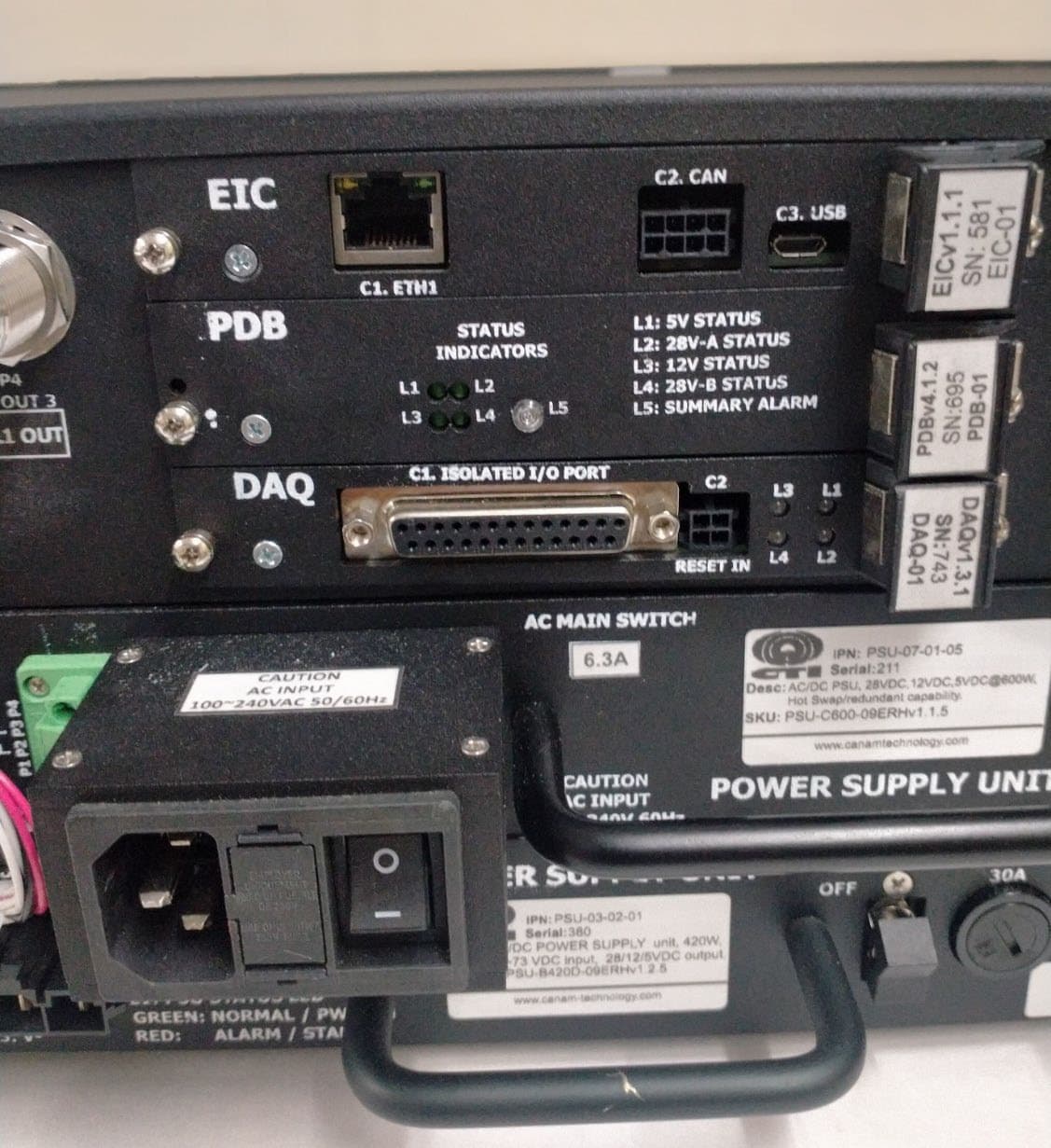
TCJ-M4BBDAUU
Apr 21, 2026Bi Directional Amplifier
Equipment Class
B9B - Part 90 Class B Industrial Booster (non-SMR)
TCJ-M4BBDAV
Jul 14, 2015MARK-IV Broadband (Class-B) Signal Booster
Equipment Class
B9B - Part 90 Class B Industrial Booster (non-SMR)
TCJ-M4DBDA7
Sep 17, 2012MARK-IV Digital Narrowband (Class-A) Signal Booster
Equipment Class
TNB - Licensed Non-Broadcast Station Transmitter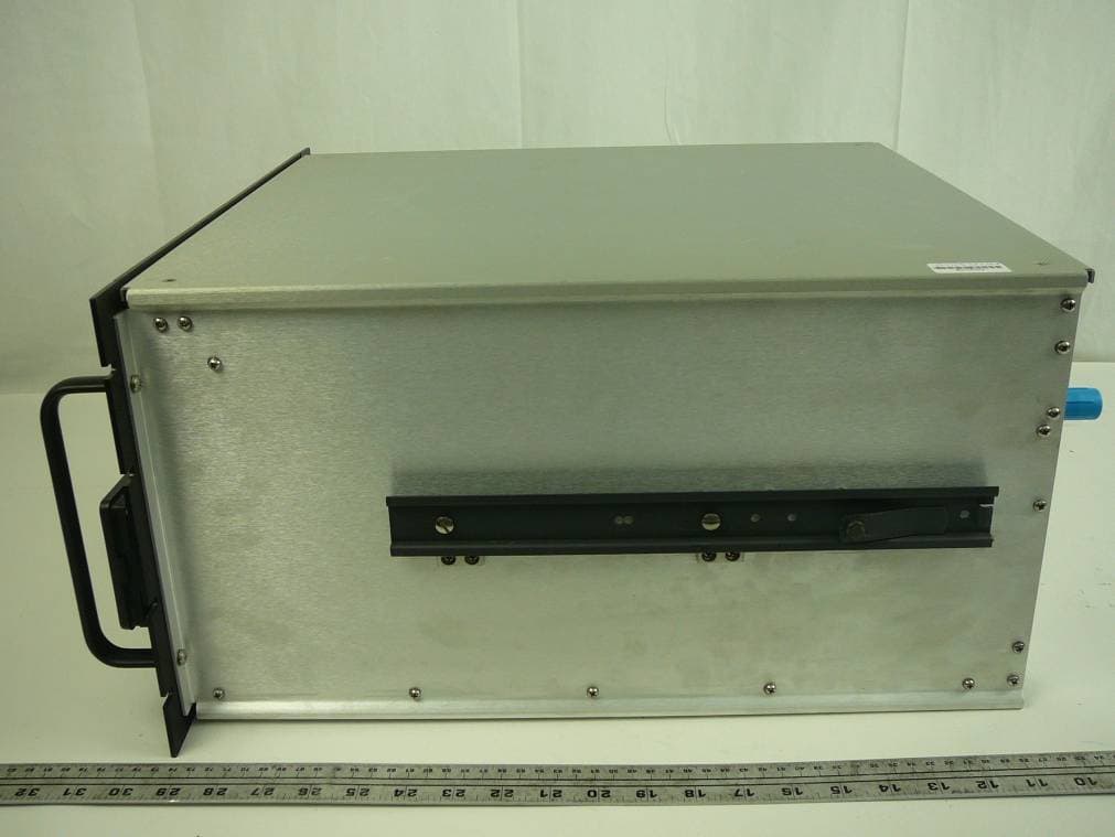
TCJ-M4DBDAV
Jun 23, 2011MARK-IV Digital Narrowband (Class-A) Signal Booster
Equipment Class
AMP - Amplifier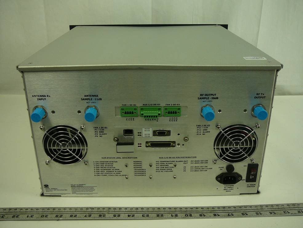
TCJ-M4DBDAU
Jun 16, 2011MARK-IV Digital Narrowband (Class-A) Signal Booster
Equipment Class
AMP - Amplifier