TCJ-M4BBDAVMARK-IV Broadband (Class-B) Signal Booster
Canam Technology, Inc
Click to zoom
Application Details
- Equipment Class
- B9B - Part 90 Class B Industrial Booster (non-SMR)
- Date of Grant
- Jul 14, 2015
- Application Purpose
- Original Equipment
- Date of Application
- Jul 06, 2015
- Equipment Note
- MARK-IV Broadband (Class-B) Signal Booster
- Frequency Range
- 150.00000000 - 174.00000000
- Company
- Canam Technology, Inc
- Country
- United States
Documents & Files
Document Text
Text extracted from the exhibit documents filed with the FCC. Open a document above to read the original.
Users Manual
MARK-IV VHF BROADBAND SIGNAL BOOSTER M4BBDAV USER’S MANUAL REVISION 0 SUBMITTED BY: CANAM TECHNOLOGY, INC. April, 2015 CANAM TECHNOLOGY, INC. (CTI) MARK-IV VHF BROADBAND SIGNAL BOOSTER M4BBDAV USER’S MANUAL Page 2 of 13 Rev0 April/2015 Part 90 Signal Boosters THIS IS A 90.219 CLASS B DEVICE WARNING. This is NOT a CONSUMER device. It is designed for installation by FCC LICENSEES and QUALIFIED INSTALLERS. You MUST have an FCC LICENSE or express consent of an FCC Licensee to operate this device. You MUST register Class B signal boosters (as defined in 47 CFR 90.219) online at www.fcc.gov/signal-boosters/registration. Unauthorized use may result in significant forfeiture penalties, including penalties in excess of $100,000 for each continuing violation.” CANAM TECHNOLOGY, INC. (CTI) MARK-IV VHF BROADBAND SIGNAL BOOSTER M4BBDAV USER’S MANUAL Page 3 of 13 Rev0 April/2015 TABLE OF CONTENTS Section A. INTRODUCTION ..................................................................................... 4 Section B. SYSTEM DESCRIPTION ........................................................................... 6 Section C. PHYSICAL OVERWIEW .......................................................................... 7 Section D. START - UP .............................................................................................. 9 D.1 ACCESSING D.U.T. WEB SERVER ................................................................... 9 D.1.1 Connect D.U.T to P.C computer using a crossover cable ................... 9 D.1.2 Connect D.U.T to local area network ................................................... 10 D.2 USING AND SETTING UP D.U.T...................................................................... 11 Section E. RF CONNECTIONS .............................................................................. 12 CANAM TECHNOLOGY, INC. (CTI) MARK-IV VHF BROADBAND SIGNAL BOOSTER M4BBDAV USER’S MANUAL Page 4 of 13 Rev0 April/2015 Section A. INTRODUCTION The MARK-IV VHF Broadband Signal Booster (M4BBDAV) is a Class “B” Industrial Signal Booster for FCC Part 90 PLMRS Public Safety Agencies used to operate within range 150-174 MHz for Land Mobile Radio. This document is the M4BBDAV User’s Guide Manual, intended for the Radio Technical Personnel. This manual is intended to be used with the M4BBDAV Equipment only. It is not to be used with any other equipment unless it is authorized by Canam Technology, Inc. Canam Technology, Inc. provide this document “as is” without any warranty of any kind. Canam Technology may make changes to the equipment, software or specifications in this document at any time without notice to the user. These changes will be notified to the party responsible for FCC compliance and they will be incorporated in future releases of this document. Changes or modifications not expressly approved by the party responsible for compliance could void the user's authority to operate the equipment” This document may contain typographical errors and technical inaccuracies. Canam Technology will not accept any liability from the use and misuse of this manual, the information contained within, or the consequences of any actions resulting from the use of this information. CANAM TECHNOLOGY, INC. (CTI) MARK-IV VHF BROADBAND SIGNAL BOOSTER M4BBDAV USER’S MANUAL Page 5 of 13 Rev0 April/2015 Signal boosters such as the M4BBDAV generate radio signals and, therefore, electromagnetic fields. The technical personnel should have a complete understanding of FCC CFR Title 47 sections 1.1307 and 1.1310. Recommendations are included in this Manual, but they do not substitute the FCC guidelines. M4BBDAV Key Features: Broadband Class B Signal Booster, per FCC Part 90. Maximum Output Power at the antenna port +37 dBm per carrier. This device may require the use of antennas for proper functioning, depending on the application. The installation of the antennas should be performed by qualified technical personnel. All antennas should be fixed mounted and physically secured to one location The people must be away from the antennas at least 1.0 meters to comply with the RF Human Maximum Permissible Exposure limits, as long as the antenna system gain is lower than 7 dBi. If greater gain is used the separation should be increased, please refer to the FCC Rules. If service should be performed on the antenna, please shut down the transmitter or lower its power in order to comply with the maximum permissible exposure. CANAM TECHNOLOGY, INC. (CTI) MARK-IV VHF BROADBAND SIGNAL BOOSTER M4BBDAV USER’S MANUAL Page 6 of 13 Rev0 April/2015 Section B. SYSTEM DESCRIPTION The system houses multi-carrier linear broadband power amplifiers and automatic level control. The amplifiers are designed with special linear characteristics for continuous operation, 100% duty cycle 24 hours/7 days a week. Its modular construction allows easy access to the amplifier modules and power supply. It has a maximum gain around 60dB across the band. The output power amplifier P1dB Compression point is around 20 Watts (+43 dBm). They also have an automatic gain control range greater than 25dB. The amplifiers modules are bolted down onto a heat-sink base. These heat sinks have adequate capacity to dissipate five times the maximum anticipated heat being generated by the amplifiers. It is recommended the temperature of the room be maintained below 80 0 F to assure the longest possible life of the amplifier transistors. The power supply has +28 VDC module for the amplifiers, equipped with over current and over voltage protection among other features. It will immediately drop the supply voltage to prevent damage to other components. The unit’s operational parameters are stored in the non-volatile memory of the embedded controller; this allows the booster to operate on a standalone basis. The built-in Web Server provides a Graphical User Interface (GUI) to ease in remote monitoring & control. Access is obtained via a PC’s Web Browser and a TCP/IP connection t…
Text truncated - open the document above for the full version.
Users Manual
MARK-IV VHF BROADBAND SIGNAL BOOSTER M4BBDAV OPERATIONS & MAINTENANCE (O&M) MANUAL REVISION 0 SUBMITTED BY: CANAM TECHNOLOGY, INC. April, 2015 CANAM TECHNOLOGY, INC. (CTI) MARK-IV VHF BROADBAND SIGNAL BOOSTER M4BBDAV O&M MANUAL Page 2 of 39 Rev0 April/2015 Part 90 Signal Boosters THIS IS A 90.219 CLASS B DEVICE WARNING. This is NOT a CONSUMER device. It is designed for installation by FCC LICENSEES and QUALIFIED INSTALLERS. You MUST have an FCC LICENSE or express consent of an FCC Licensee to operate this device. You MUST register Class B signal boosters (as defined in 47 CFR 90.219) online at www.fcc.gov/signal-boosters/registration. Unauthorized use may result in significant forfeiture penalties, including penalties in excess of $100,000 for each continuing violation.” CANAM TECHNOLOGY, INC. (CTI) MARK-IV VHF BROADBAND SIGNAL BOOSTER M4BBDAV O&M MANUAL Page 3 of 39 Rev0 April/2015 TABLE OF CONTENTS Section A. INTRODUCTION ..................................................................................... 6 Section B. GLOSSARY ............................................................................................. 8 Section C. SAFETY PRECAUTIONS .......................................................................... 9 C.1 EQUIPMENT HANDLING AND INSTALLATION ............................................... 9 C.2 POWER SUPPLIES ............................................................................................. 9 C.3 MCPA MODULES ............................................................................................ 9 C.4 RF EXPOSURE ................................................................................................... 9 C.5 MOVING PARTS ............................................................................................ 10 Section D. THEORY OF OPERATION .................................................................... 11 D.1 DESCRIPTION ................................................................................................. 11 D.2 FUNCTIONAL BLOCK DIAGRAM ................................................................. 12 D.3 FEATURES ........................................................................................................ 13 D.4 SPECIFICATIONS ............................................................................................ 14 D.5 FRONT AND REAR PANEL PORTS AND INTERFACES.................................. 17 D.6 LCD-DISPLAY & KEYPAD ASSEMBLY ........................................................... 19 Section E. INITIAL CONFIGURATION ................................................................... 22 E.1 GENERAL GUIDELINES REGARDING RF CONNECTIONS & OPERATIONS WITH TEST INSTRUMENTS ......................................................................................... 23 E.2 ANTENNA INSTALLATION .............................................................................. 24 Section F. WEB-SERVER GRAPHICAL USER INTERFACE .................................... 25 F.1 FIRST-TIME START CONFIGURATION ............................................................ 25 F.1.1 CONNECTING SYSTEM DIRECTLY TO PC COMPUTER ........................... 25 F.1.2 CONNECTING SYSTEM TO LOCAL AREA NETWORK ............................. 28 F.2 WEB SERVER OPERATIONS ........................................................................... 30 F.2.1 MAIN STATUS PAGE ................................................................................... 31 F.2.2 MAIN SETTINGS PAGE ............................................................................... 35 F.2.2.1 iALC Control ........................................................................................... 35 F.2.2.2 MCPA Control: ....................................................................................... 36 F.2.2.3 Updating operational settings ............................................................ 37 CANAM TECHNOLOGY, INC. (CTI) MARK-IV VHF BROADBAND SIGNAL BOOSTER M4BBDAV O&M MANUAL Page 4 of 39 Rev0 April/2015 TABLES Table 1 – Front Panel details ................................................................................................................... 17 Table 2 – Rear Panel details. .................................................................................................................. 18 Table 3 – Alarm available at the Front Panel LCD ............................................................................. 20 Table 4 – Meters available at the Front Panel LCD............................................................................ 21 Table 5 – Network Settings available at the Front Panel LCD.......................................................... 21 CANAM TECHNOLOGY, INC. (CTI) MARK-IV VHF BROADBAND SIGNAL BOOSTER M4BBDAV O&M MANUAL Page 5 of 39 Rev0 April/2015 TABLE OF FIGURES Figure 1 – M4BBDAV General Block Diagram ..................................................................................... 12 Figure 2 - Front Panel details .................................................................................................................. 17 Figure 3 - Rear Panel details. .................................................................................................................. 18 Figure 4 – LCD and Keypad Interface .................................................................................................. 19 Figure 5 – System connected directly to PC computer. ................................................................... 25 Figure 6 – Local Area Connection Status. ........................................................................................... 26 Figure 7 – Local Area Connection Properties. .................................................................................... 27 Figure 8 – System connected into local area network. .................................................................... 28 Figure 9 – Main Status page ...........................................…
Text truncated - open the document above for the full version.
Attestation Statements
5318 East 2nd Street, Suite 700 Long Beach, CA 90803 Ph: (562)856-0178, Fax: (562)856-0188 Web Site www.canam-technology.com E-mail: [email protected] April 30th, 2015 Attestation Exhibit We, Canam Technology, Inc., state our sole responsibility that all warning labels and Class B disclosure of the booster (FCC ID: TCJ-M4BBDAV) are shown in all documentations such as user manual and data sheet. These documents are supplied with the booster, and can be also found online at our website http://www.canam-technology.com/ing/MarkIV_BBDA.html. We declare that the warning label will be visible on the outside packaging of the device as the well as on the device itself. Sincerely, Victor Bermudez Vice-President Canam Technology, Inc. 5318 E 2nd Street #700 Long Beach, CA 90803 USA [email protected] www.canam-technology.com
Cover Letter(s)
5318 East 2nd Street, Suite 700 Long Beach, CA 90803 Ph: (562)856-0178, Fax: (562)856-0188 Web Site www.canam-technology.com E-mail: [email protected] March 19 th , 2015 To: Bay Area Compliance Laboratories Corp. 1274 Anvilwood Avenue Sunnyvale, CA 94089 Dear Sir/Madam, Re: Project Authorization Letter We, Canam Technology Inc. hereby authorize Bay Area Compliance Laboratories Corp to ac t as a laboratory for testing and test report generation for the following project(s): MARK-IV Digital 800 MHz Narrow band Signal Booster for operations under FCC Part 90 in 806 – 817 MHz and 851 – 862 MHz frequency bands, model M4DBDA8. We affirm that between BACL and Canam Technology Inc. any difference in understanding, including test plan, measurement methods, applicable standards and relevant procedures and processes have been resolved prior to commencement of testing activities. Sincerely, Victor Bermudez Vice-President Canam Technology, Inc. 5318 E 2nd Street #700 Long Beach, CA 90803 USA [email protected] www.canam-technology.com
Cover Letter(s)
5318 East 2nd Street, Suite 700 Long Beach, CA 90803 Ph: (562)856-0178, Fax: (562)856-0188 Web Site www.canam-technology.com E-mail: [email protected] FCC Confidential Authorization April 30 th , 2015 FEDERAL COMMUNICATIONS COMMISSIONS Authorization and Evaluation Division 7435 Oakland Mills Road Columbia, MD 21046 Subject: Confidentiality Request regarding application for certification of TCJ-M4BBDAV. In accordance with Sections 0.457 and 0.459 of the Commission’s Rules, Canam Technology Inc. hereby requests long-term confidential treatment of information accompanying this application as outlined below: Block Diagram. Circuit Description. Schematic Diagrams. Parts List (Bill of Materials). As well as short-term confidential treatment of information accompanying this application as outlined below: User’s Manual. Operation and Maintenance (O&M) Manual. Internal photos. The above materials contain proprietary and confidential information not customarily released to the public. The public disclosure of these materials provides unjustified benefits to its competitors in the market. Sincerely, Victor Bermudez Vice-President Canam Technology, Inc. 5318 E 2nd Street #700 Long Beach, CA 90803 USA [email protected] www.canam-technology.com
External Photos
Canam Technology, Inc. FCC ID: TCJ-M4BBDAV Report Number: R1503301-90 Rev A Page 65 of 71 FCC Part 90 Test Report 13 Exhibit C - EUT Photographs 13.1 EUT Front View 13.2 EUT Rear View Canam Technology, Inc. FCC ID: TCJ-M4BBDAV Report Number: R1503301-90 Rev A Page 66 of 71 FCC Part 90 Test Report 13.3 EUT Top View 13.4 EUT Bottom View Canam Technology, Inc. FCC ID: TCJ-M4BBDAV Report Number: R1503301-90 Rev A Page 67 of 71 FCC Part 90 Test Report 13.5 EUT Side View 1 13.6 EUT Side View 2
ID Label/Location Info
MARK-IV VHF BROADBAND SIGNAL BOOSTER M4BBDAV FCC ID: TCJ - M4BBDAV REVISION 0 SUBMITTED BY: CANAM TECHNOLOGY, INC. April, 2015 CANAM TECHNOLOGY, INC. (CTI) MARK-IV VHF BROADBAND SIGNAL BOOSTER M4BBDAV FCC LABEL SAMPLE Page 2 of 2 Rev0 March/2015 I I . . L L a a b b e e l l P P i i c c t t u u r r e e s s Figure 1 – Labels Location Rear Panel details WARNING. This is NOT a CONSUMER device. It is designed for installation by FCC LICENSEES and QUALIFIED INSTALLERS. You MUST have an FCC LICENSE or express consent of an FCC Licensee to operate this device. You MUST register Class B signal boosters (as defined in 47 CFR 90.219) online at www.fcc.gov/signal-boosters/registration. Unauthorized use may result in significant forfeiture penalties, including penalties in excess of $100,000 for each continuing violation. Part 90 Signal Boosters THIS IS A 90.219 CLASS B DEVICE Figure 2 – FC C ID Label design example NOTE: This is a FCC Label sample. Model and Serial Number Label Location FCC Label Location
Internal Photos
Canam Technology, Inc. FCC ID: TCJ-M4BBDAV Report Number: R1503301-90 Rev A Page 68 of 71 FCC Part 90 Test Report 13.7 EUT Cover off View 13.8 iALC Module Front View 13.9 iALC Module Rear View Canam Technology, Inc. FCC ID: TCJ-M4BBDAV Report Number: R1503301-90 Rev A Page 69 of 71 FCC Part 90 Test Report 13.10 iALC Module Cover off View 13.11 ECM Module Front View Canam Technology, Inc. FCC ID: TCJ-M4BBDAV Report Number: R1503301-90 Rev A Page 70 of 71 FCC Part 90 Test Report 13.12 ECM Module Back View 13.13 ECM Module Top View Canam Technology, Inc. FCC ID: TCJ-M4BBDAV Report Number: R1503301-90 Rev A Page 71 of 71 FCC Part 90 Test Report 13.14 ECM Bottom View --- END OF REPORT ---
RF Exposure Info
Canam Technology, Inc. FCC ID: TCJ-M4BBDAV Report Number: R1503301-90 Rev A Page 10 of 71 FCC Part 90 Test Report 4 FCC §2.1091 - RF Exposure Information 4.1 Applicable Standards FCC §2.1091, (a) Requirements of this section are a consequence of Commission responsibilities under the National Environmental Policy Act to evaluate the environmental significance of its actions. See subpart I of part 1 of this chapter, in particular §1.1307(b). According to §1.1310 and §2.1091 RF exposure is calculated. Limits for Occupational/Controlled Exposure Frequency Range (MHz) Electric Field Strength (V/m) Magnetic Field Strength (A/m) Power Density (mW/cm 2 ) Averaging Time (minutes) (A) Limits for Occupational/Controlled Exposure 0.3-1.34 614 1.63 *(100) 6 1.34-30 1842/f 4.89/f *(900/f 2 ) 6 30-300 61.4 0.163 1.0 6 300-1500 / / f/300 6 1500-100,000 / / 5 6 f = frequency in MHz * = Plane-wave equivalent power density 4.2 MPE Prediction Predication of MPE limit at a given distance, Equation from OET Bulletin 65, Edition 97-01 S = PG/4R² Where: S = power density P = power input to antenna G = power gain of the antenna in the direction of interest relative to an isotropic radiator R = distance to the center of radiation of the antenna 4.3 Conclusion The device complies with the MPE requirements by providing a safe separation distance of at least 100 cm between the antenna with maximum 0 dBi gain, including any radiating structure, and any persons when normally operated. Maximum peak output power at antenna input terminal (dBm): 36.7 Maximum peak output power at antenna input terminal (mW): 4677.4 Prediction distance (cm): 20 Prediction frequency (MHz): 162 Maximum Antenna Gain, typical (dBi): 0 Maximum Antenna Gain (numeric): 1 Power density of prediction frequency at 100 cm (mW/cm 2 ): 0.37 MPE limit for controlled exposure at prediction frequency (mW/cm 2 ): 1.0
Test Report
Note: This test report is prepared for the customer shown above and for the device described herein. It may not be duplicated or used in part without prior written consent from Bay Area Compliance Laboratories Corp. This report must not be used by the customer to claim product certification, approval, or endorsement by A2LA* or any agency of the Federal Government. * This report may contain data that are not covered by the A2LA accreditation and are marked with an asterisk “*” (Rev.3) FCC PART 90 TEST AND MEASUREMENT REPORT For Canam Technology, Inc. 5318 East 2 nd St., #700, Long Beach, CA 90803, USA FCC ID: TCJ-M4BBDAV Report Type: Original Report Product Type: MARK-IV VHF (Class-B) Signal Booster Prepared By: Simon Ma Test En gineer Report Number: R1503301-90 Rev A Report Date: 2015-06-25 Reviewed By: Bo Li RF Lead Bay Area Compliance Laboratories Corp. 1274 Anvilwood Avenue, Sunnyvale, CA 94089, USA Tel: (408) 732-9162 Fax: (408) 732 9164 Canam Technology, Inc. FCC ID: TCJ-M4BBDAV Report Number: R1503301-90 Rev A Page 2 of 71 FCC Part 90 Test Report TABLE OF CONTENTS 1. General Information ............................................................................................................................................. 5 1.1 PRODUCT DESCRIPTION FOR EQUIPMENT UNDER TEST (EUT)........................................................................ 5 1.2 MECHANICAL DESCRIPTION ........................................................................................................................... 5 1.3 OBJECTIVE ...................................................................................................................................................... 5 1.4 RELATED SUBMITTAL(S)/GRANT(S) ............................................................................................................... 5 1.5 TEST METHODOLOGY ..................................................................................................................................... 5 1.6 MEASUREMENT UNCERTAINTY ...................................................................................................................... 6 1.7 TEST FACILITY ............................................................................................................................................... 6 2 System Test Configuration ................................................................................................................................... 8 2.1 JUSTIFICATION ................................................................................................................................................ 8 2.2 EUT EXERCISE SOFTWARE ............................................................................................................................. 8 2.3 EQUIPMENT MODIFICATIONS .......................................................................................................................... 8 2.4 INTERNAL CONFIGURATION............................................................................................................................ 8 2.5 LOCAL SUPPORT EQUIPMENT ......................................................................................................................... 8 2.6 LOCAL SUPPORT EQUIPMENT POWER SUPPLY AND LINE FILTERS .................................................................. 8 2.7 EXTERNAL I/O CABLING LIST AND DETAILS .................................................................................................. 8 3 Summary of Test Results ...................................................................................................................................... 9 4 FCC §2.1091 - RF Exposure Information ......................................................................................................... 10 4.1 APPLICABLE STANDARDS ............................................................................................................................. 10 4.2 MPE PREDICTION ......................................................................................................................................... 10 4.3 CONCLUSION ................................................................................................................................................ 10 5 FCC §2.1046 & §90.219(e) – RF Output Power ............................................................................................... 11 5.1 APPLICABLE STANDARD ............................................................................................................................... 11 5.2 TEST PROCEDURE ......................................................................................................................................... 11 5.3 TEST EQUIPMENT LIST AND DETAILS ........................................................................................................... 11 5.4 TEST ENVIRONMENTAL CONDITIONS............................................................................................................ 11 5.5 TEST RESULTS .............................................................................................................................................. 12 6 FCC §2.1049 & §90.219(e) – Occupied Bandwidth & Emission Mask ........................................................... 13 6.1 APPLICABLE STANDARD ............................................................................................................................... 13 6.2 TEST PROCEDURE ......................................................................................................................................... 13 6.3 TEST EQUIPMENT LIST AND DETAILS ........................................................................................................... 14 6.4 TEST ENVIRONMENTAL CONDITIONS............................................................................................................ 14 6.5 TEST RESULTS ...............…
Text truncated - open the document above for the full version.
Test Setup Photos
Canam Technology, Inc. FCC ID: TCJ-M4BBDAV Report Number: R1503301-90 Rev A Page 63 of 71 FCC Part 90 Test Report 12 Exhibit B - Test Setup Photographs 12.1 Radiated Emission below 1 GHz–Front View 12.2 Radiated Emission below 1 GHz–Rear View Canam Technology, Inc. FCC ID: TCJ-M4BBDAV Report Number: R1503301-90 Rev A Page 64 of 71 FCC Part 90 Test Report 12.3 Radiated Emission above 1 GHz–Front View 12.4 Radiated Emission above 1 GHz–Rear View
Contact Information
Applicant
Victor J. Bermudez
Test Firm
Bay Area Compliance Laboratories Corp.Lisa Tang
Technical Specifications
| # | Rule Parts | Frequency Range | Power Output | Emission | Tolerance |
|---|---|---|---|---|---|
| 4 | 9 | 150 MHz - 174 MHz | 5 W | G1E | Amp |
Other Applications from Canam Technology, Inc
TCJ-M4BBDAUU
Apr 21, 2026Bi Directional Amplifier
Equipment Class
B9B - Part 90 Class B Industrial Booster (non-SMR)
TCJ-M4DBDA7
Sep 17, 2012MARK-IV Digital Narrowband (Class-A) Signal Booster
Equipment Class
TNB - Licensed Non-Broadcast Station Transmitter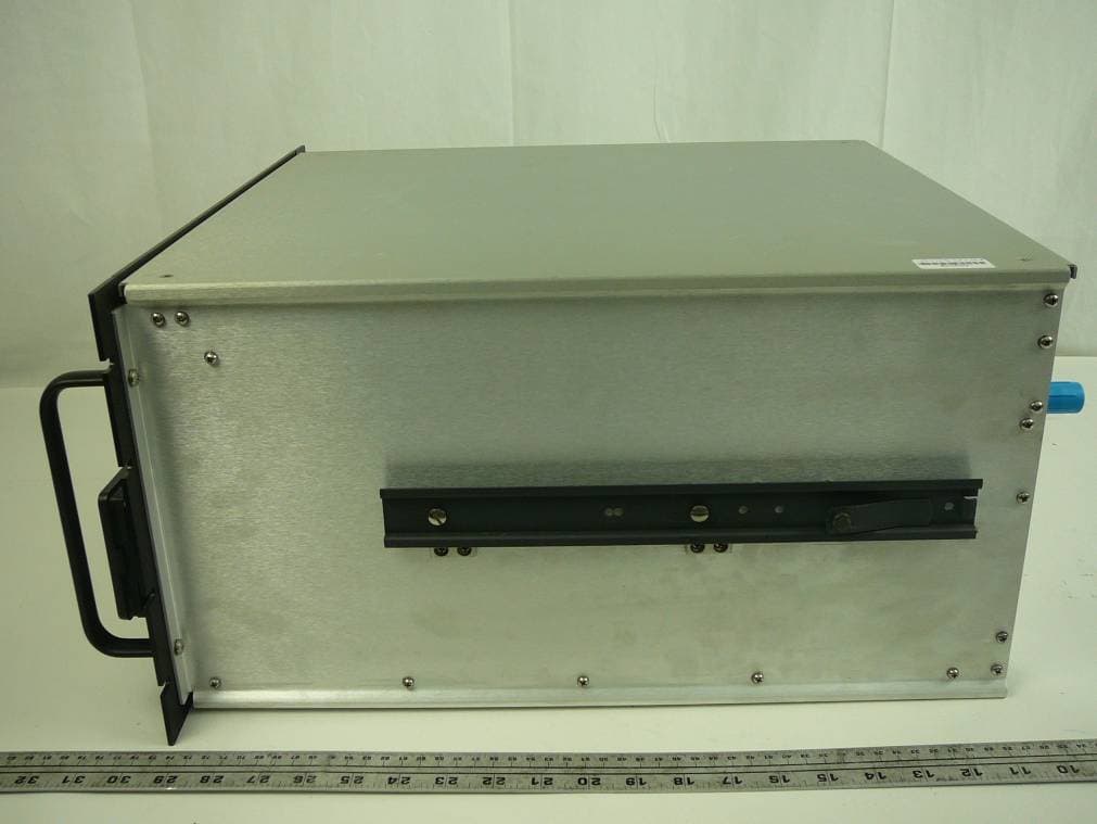
TCJ-M4DBDAV
Jun 23, 2011MARK-IV Digital Narrowband (Class-A) Signal Booster
Equipment Class
AMP - Amplifier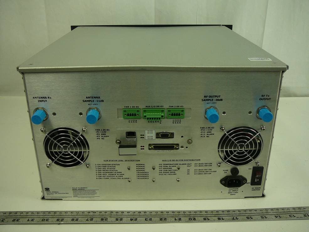
TCJ-M4DBDAU
Jun 16, 2011MARK-IV Digital Narrowband (Class-A) Signal Booster
Equipment Class
AMP - Amplifier
TCJ-M4BBDAU
Feb 13, 2006Power Amplifier
Equipment Class
AMP - Amplifier