TCJ-M4BBDAUUBi Directional Amplifier
Canam Technology, Inc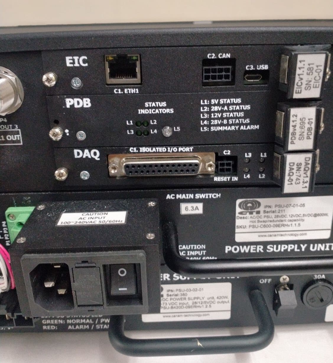
Click to zoom
Application Details
- Equipment Class
- B9B - Part 90 Class B Industrial Booster (non-SMR)
- Date of Grant
- Apr 21, 2026
- Application Purpose
- Original Equipment
- Equipment Note
- Bi Directional Amplifier
- Frequency Range
- 406.10000000 - 430.00000000
- Company
- Canam Technology, Inc
- Country
- United States
Documents & Files
Document Text
Text extracted from the exhibit documents filed with the FCC. Open a document above to read the original.
Attestation Statements
CANAM TECHNOLOGY, INC (CTI) U.S Agent Designation for Service of Process TCJ-M4BBDAUU U.S. Agent Letter.docx Page 1 of 2 U.S Agent Designation for Service of Process ATTENTION: Federal Communications Commission Authorization and Evaluation Division 7435 Oakland Mills Road Columbia, MD 21046 USA REGARDING: FCC Certification – Section 2.911(d)(7) Information Designated U.S. Agent Company Name: Canam Technology, Inc. Contact Name: Victor Bermudez Street Address: 5318 E 2nd Street #700 City/Province/Zip: Long Beach, CA 90803 Telephone No: +1(562)856-0178 ext. 262 Email: [email protected] FRN #: 0013448808 This letter is to confirm that we (“the Designated U.S. Agent) have accepted the responsibility to act as the Designated U.S. Agent for Service of Process as required by section 47 CFR 2.911(d)(7) on behalf of the Applicant noted below. U.S. Agent Signature: Date: December 8 th , 2025 Signed by (Printed Name/Title): Victor Bermudez/Vice President The Applicant confirms its explicit consent and acknowledges that they must maintain an agent for no less than one year after terminating all marketing and importation OR the conclusion of any Commission-related proceeding involving the equipment. The applicant further acknowledges their responsibility to inform the FCC whenever the Designated U.S. Agent information above changes. Applicant Company name: Canam Technology, Inc. Grantee FRN: 0013448808 Grantee Code: TCJ FCC ID: TCJ-M4BBDAUU Contact Name: Victor Bermudez Street Address: 5318 E 2nd Street #700 CANAM TECHNOLOGY, INC (CTI) U.S Agent Designation for Service of Process TCJ-M4BBDAUU U.S. Agent Letter.docx Page 2 of 2 City/Province/Zip: Long Beach, CA 90803 Telephone No: +1(562)856-0178 ext. 262 Email: [email protected] Applicant Signature: Date: December 8 th , 2025 Signed by (Printed Name/Title): Victor Bermudez/Vice President
Attestation Statements
CANAM TECHNOLOGY, INC (CTI) FCC Attestation statement letter TCJ-M4BBDAUU FCC covered list attestation form.docx Page 1 of 2 FCC Attestation statement letter Federal Communications Commission Authorization and Evaluation Division 7435 Oakland Mills Road Columbia, MD 21046 USA Date: December 8 th , 2025 Ref: Attestation Statements Part 2.911(d)(5)(i) Filing FCC ID: TCJ-M4BBDAUU Canam Technology, Inc. (“the applicant”) certifies that the equipment for which authorization is sought is not “covered” equipment prohibited from receiving an equipment authorization pursuant to section 2.903 of the FCC rules. Canam Technology, Inc. (“the applicant”) certifies that the equipment for which authorization is sought does not include cybersecurity or anti-virus software produced or provided by Kaspersky Lab, Inc. or any of its successors and assignees, including equipment with integrated Kaspersky Lab, Inc. (or any of its successors and assignees) cybersecurity or anti-virus software pursuant to DA-24-886 and KDB 986446 D01 Covered Equipment Guidance section B(2a). The device is inherently compliant, as its main processor runs on an ARM-based custom Linux distribution with limited storage space. Sincerely, Victor Bermudez Vice President Canam Technology, Inc. 5318 E 2nd Street #700 Long Beach, CA 90803 USA [email protected] www.canamtechnology.com CANAM TECHNOLOGY, INC (CTI) FCC Attestation statement letter TCJ-M4BBDAUU FCC covered list attestation form.docx Page 2 of 2 Federal Communications Commission Authorization and Evaluation Division 7435 Oakland Mills Road Columbia, MD 21046 USA Date: December 8 th , 2025 Ref: Attestation Statements Part 2.911(d)(5)(ii) Filing FCC ID: TCJ-M4BBDAUU Canam Technology, Inc. (“the applicant”) certifies that, as of the date of the filing of the application, the applicant is not identified on the Covered List (as a specifically named entity or any of its subsidiaries or affiliates) as an entity producing “covered” equipment. Sincerely, Victor Bermudez Vice President Canam Technology, Inc. 5318 E 2nd Street #700 Long Beach, CA 90803 USA [email protected] www.canamtechnology.com
Cover Letter(s)
CANAM TECHNOLOGY, INC (CTI) FCC Confidential Authorization TCJ-M4BBDAUU Warning labels attestation.docx Page 1 of 1 FCC Attestation Regarding Warning Labels December 8 th , 2025 Federal Communications Commission Authorization and Evaluation Division 7435 Oakland Mills Road Columbia, MD, 21046 United States of America SUBJECT: LETTER FOR WARNING LABEL FCC ID: TCJ-M4BBDAUU Pursuant to 47 C.F.R. § 90, the required warning label and Class B notification messages will be affixed to the device, displayed in online and point-of-sale marketing materials and printed on the external packaging. Sample labels can be found in the exhibit titled 'TCJ-M4BBDAUU FCC ID Label Info.pdf.' Regards, Victor Bermudez Vice President Canam Technology, Inc. 5318 E 2nd Street #700 Long Beach, CA 90803 USA [email protected] www.canamtechnology.com
Cover Letter(s)
CANAM TECHNOLOGY, INC (CTI) FCC Confidential Authorization TCJ-M4BBDAUU FCC Confidentiality Request.docx Page 1 of 2 FCC Confidential Authorization December 8 th , 2025 Federal Communications Commission Authorization and Evaluation Division 7435 Oakland Mills Road Columbia, MD, 21046 United States of America SUBJECT: CONFIDENTIALITY REQUEST FOR CERTIFICATION OF TCJ-M4BBDAUU In accordance with Sections 0.457 and 0.459 of the Commission’s Rules, Canam Technology Inc. hereby requests permanent confidential treatment of information accompanying this application as outlined below: • Schematics • Block Diagram • Part List (Bill of Materials) • Operation and Maintenance (O&M) Manual • User’s Manual • Internal photos The materials referenced above contain proprietary and confidential information that is not customarily disclosed to the public. Public release of this information would confer undue competitive advantage to third parties and compromise both the integrity of the equipment and the confidentiality of the associated documentation. This product is a specialized, non-consumer device that is not intended for public access. It must be maintained in a secure environment and serviced exclusively by authorized professionals. This device will be sold to a limited institutional audience. The associated documents will be shared solely with Canam Technology, Inc. partners and system integrators for the purposes of service and maintenance, strictly under the terms of a Non-Disclosure Agreement (NDA). A sample NDA is included in this application for reference. Yours sincerely, Victor Bermudez Vice President Canam Technology, Inc. 5318 E 2nd Street #700 Long Beach, CA 90803 CANAM TECHNOLOGY, INC (CTI) FCC Confidential Authorization TCJ-M4BBDAUU FCC Confidentiality Request.docx Page 2 of 2 USA [email protected] www.canamtechnology.com
External Photos
TCJ-M4BBDAUU MARK-IV UHF BROADBAND SIGNAL BOOSTER External photos Document Title: External photos Revision: 0 Date: 2025-12-09 Instruction modification log: Revision Date Modification 0 2025-12-09 First revision Submitted by: Canam Technology, Inc. CANAM TECHNOLOGY, INC (CTI) TCJ-M4BBDAUU MARK-IV UHF BROADBAND SIGNAL BOOSTER External photos 1 PURPOSE This document presents the external photos of the Mark-IV UHF Broadband Signal Booster for FCC Part 90 certification. 2 MARK-IV EXTERNAL PHOTOS Figure 1. Mark-IV top view. Figure 2. Mark-IV front view. CANAM TECHNOLOGY, INC (CTI) TCJ-M4BBDAUU MARK-IV UHF BROADBAND SIGNAL BOOSTER External photos TCJ-M4BBDAUU External photos.docx Page 3 of 3 Figure 3. Mark-IV rear view. Figure 4. Mark-IV side view. ____________________________________________________________________________________________________________________________________________________________________________ Page 78 of 85 Test Report No 250504.4 22 nd October 2025 This report may not be reproduced except in full. 9. PHOTOGRAPHS Equipment Under Test ____________________________________________________________________________________________________________________________________________________________________________ Page 79 of 85 Test Report No 250504.4 22 nd October 2025 This report may not be reproduced except in full. Equipment Under Test Labels ____________________________________________________________________________________________________________________________________________________________________________ Page 80 of 85 Test Report No 250504.4 22 nd October 2025 This report may not be reproduced except in full. Radiated Emissions Test Set Ups Additional External Photos – Front View – Front View Top view Bottom View Right Hand Side Left Hand Side Rear View Rear View Rear View Left Hand Side Rear View Left Hand Side Rear View - Centre Rear View – Right Hand Side Rear View – Right Hand Side
ID Label/Location Info
TCJ-M4BBDAUU MARK-IV UHF BROADBAND SIGNAL BOOSTER FCC ID Label Details Document Title: FCC ID Label Details Revision: 0 Date: 2025-12-09 Instruction modification log: Revision Date Modification 0 2025-12-09 First revision Submitted by: Canam Technology, Inc. CANAM TECHNOLOGY, INC (CTI) Subject FCC ID Label Details 1 PURPOSE This document presents the design and pictures of the Mark-IV UHF Broadband Signal Booster FCC ID label. 2 LABEL DESIGN Figure 1. Product label design. Figure 2. FCC Part 15 compliance label design. CANAM TECHNOLOGY, INC (CTI) Subject FCC ID Label Details TCJ-M4BBDAUU FCC ID Label Info.docx Page 3 of 5 Figure 3. FCC Part 90 warning label design. CANAM TECHNOLOGY, INC (CTI) Subject FCC ID Label Details TCJ-M4BBDAUU FCC ID Label Info.docx Page 4 of 5 3 LABEL PICTURES Figure 4. Front panel. Figure 5. Perspective view. Figure 6. Front panel label placement. CANAM TECHNOLOGY, INC (CTI) Subject FCC ID Label Details TCJ-M4BBDAUU FCC ID Label Info.docx Page 5 of 5 Figure 7. Placed product label. Figure 8. Placed FCC Part 15 label. Figure 9. Placed FCC Part 90 warning label.
RF Exposure Info
TCJ-M4BBDAUU MARK-IV UHF BROADBAND SIGNAL BOOSTER RF Exposure Information Document Title: RF Exposure Information Revision: 0 Date: 2025-12-08 Instruction modification log: Revision Date Modification 0 2025-12-08 First revision Submitted by: Canam Technology, Inc. CANAM TECHNOLOGY, INC (CTI) Subject RF Exposure Information 1 PURPOSE This document presents RF Exposure recommendations for the Mark-IV UHF Broadband Signal Booster. 2 RF EXPOSURE RECOMMENDATIONS The RF Field Strengths that an individual will be exposed to while doing maintenance are well below the limits set forth by the FCC & State Laws. Nevertheless, there are Safety Precautions that should be adhered when performing any RF Tests: 1. Never Operate a Transmitter, or Booster Amplifier without adequate Load/Termination on the Output Port. 2. Ensure all Connections are tight and secured. 3. Ensure all Coaxial Cable Insulation covers the Outer Shield of the cable. 4. Do Not Touch Exposed System Ports or Coaxial Cable if system is Transmitting. 38 RF Signs Sign Examples CANAM TECHNOLOGY, INC (CTI) Subject RF Exposure Information TCJ-M4BBDAUU RF Exposure Information.docx Page 3 of 3 3 MAXIMUM ANTENNA GAIN The Input antenna and output antenna are not included with this equipment. Nevertheless, if this device is used in an application that requires direct connection to an antenna, Canam Technology recommends following the FCC guidelines for its installation. According to FCC rule § 1.1310 Radiofrequency radiation exposure limits the limits for maximum permissible exposure (MPE) are as follow: Table 1 – Limits for maximum permissible exposure (MPE) Frequency range (MHz) Power density (mW/cm 2 ) Occupational Controlled Exposures 300-1500 f/300 General Population Uncontrolled Exposure 300-1500 f/1500 The Maximum antenna gain is determined using the Friis transmission equation: 푃 푑 = ( 푃 표푢푡 ∗퐺 ) / ( 4∗휋푟 2 ) where: 푃 푑 = Power density (mW/cm2). 푃 표푢푡 = Output power (mW). 퐺 = Antenna gain (linear scale). 푟 = Distance between observation point and center of the radiator in cm The calculated Antenna Gain for r = 100cm the maximum permissible exposure (MPE) is shown in Table 2. Table 2 – Limits for maximum permissible exposure (MPE) Frequency (MHz) Maximum Antenna Gain (dBi) Occupational Controlled Exposures 480 16.04 General Population Uncontrolled Exposure 480 9.053 • Antenna Installation should be performed by qualified technical personnel. The installations instructions are for the purpose of complying with FCC RF Exposure and are not optional. • All antennas should be fixed mounted and physically secured to one location. • Non-building mounted donor antennas must be greater than 10 meters above ground. ____________________________________________________________________________________________________________________________________________________________________________ Page 75 of 85 Test Report No 250504.4 22 nd October 2025 This report may not be reproduced except in full. Exposure of humans to RF fields The product under test is a UHF bi-directional amplifier (repeater) that transmits in the 406.1 – 430.0 MHz band and the 450.0 – 470 MHz. It has been assumed that the connecting cables are short and have no associated losses. The client advises that high gain directional antennas will be used. The composite power of the amplifier when operating with a duty cycle of 100% is +37 dBm (5 watts) where 16 channels are used each with an output power of +25 dBm (316 mW). As per FCC KDB 447498 D01 and Section 2.1091 radio frequency transmitters are required to be operated in a manner that ensures the public is not exposed to RF energy levels. Calculations have been made using the General Public/Uncontrolled Exposure limits that are defined in Section 1.1310. The limits for maximum permissible exposure (MPE) have been calculated below for a worst case at 403 MHz - Occupational /Controlled exposure is f/300 which gives a limit of 1.343 mW/cm2 - General Population / Uncontrolled exposure is f/1500 which gives a limit of 0.269 mW/cm2 Minimum safe distances have been calculated below. For a Controlled Environment Power Density = 1.343 mW/cm2 = E2/3770 E= √1.343*3770 E = 71.2 V/m For an Uncontrolled Environment Power Density = 0.269 mW/cm2 = E2/3770 E= √0.269*3770 E = 31.8 V/m The rated maximum transmitter power = 0.316 W (+25 dBm). A worst case scenario duty cycle of 100% has been used for the calculations. The client advises an antenna gain of +11.3 dBi which equates to a numeric gain of 13.5. The minimum distance from the antenna at which the MPE is met is calculated from the following Field strength in V/m (FS), Transmit power in watts (P) Transmit antenna gain (G) Transmitter duty cycle (DC) Separation distance in metres (D) ____________________________________________________________________________________________________________________________________________________________________________ Page 76 of 85 Test Report No 250504.4 22 nd October 2025 This report may not be reproduced except in full. The calculation is as follows: FS = (√ (30 * P * G * DC)) / D For Uncontrolled environments, the minimum distance is: D = (√ (30 * P * G * DC)) / FS P = 5.0 W FS = E = 71.2 V/m G = 13.5 DC = 1 D = (√ (30 * 5.0 * 13.5 * 1)) / 71.2 D = 0.632 m or 63.2 cm For Controlled environments, the minimum distance is: D = (√ (30 * P * G * DC)) / FS P = 5.0 W FS = E = 31.8 V/m G = 13.5 DC = 1 D = (√ (30 * 5.0 * 13.5 * 1)) / 31.8 D = 1.415 m or 141.5 cm Result: Complies if the safe distances shown above are applied based upon the assumptions presented.
Test Report
____________________________________________________________________________________________________________________________________________________________________________ Page 1 of 85 Test Report No 250504.4 22 nd October 2025 This report may not be reproduced except in full. EMC Technologies (NZ) Ltd 47 Mackelvie St, Grey Lynn Auckland 1021 New Zealand Phone 09 360 0862 E-Mail Address: [email protected] Web Site: www.emctech.co.nz TEST REPORT Mark-IV Dual Band Broadband Bi-Directional Amplifier (Repeater) Model: M4BBDAUU tested to the Code of Federal Regulations (CFR) 47 Part 90 –Private Land Mobile Services for Canam Technology Inc This Test Report is issued with the authority of: ________________________________________ Andrew Cutler- General Manager ____________________________________________________________________________________________________________________________________________________________________________ Page 2 of 85 Test Report No 250504.4 22 nd October 2025 This report may not be reproduced except in full. Table of Contents 1. COMPLIANCE STATEMENT 3 2. RESULT SUMMARY 3 3. ATTESTATION 4 4. CLIENT INFORMATION 5 5. TEST SAMPLE DESCRIPTION 5 6. TEST RESULTS 7 7. TEST EQUIPMENT USED 77 8. ACCREDITATIONS 77 9. PHOTOGRAPHS 78 ____________________________________________________________________________________________________________________________________________________________________________ Page 3 of 85 Test Report No 250504.4 22 nd October 2025 This report may not be reproduced except in full. 1. COMPLIANCE STATEMENT The Mark-IV Dual Band Broadband Bi-Directional Amplifier (Repeater) Model: M4BBDAUU complies with the limits defined in 47 CFR Part 90 and 47 CFR Part 2 when tested in-accordance with the test methods described in ANSI C63.26: 2015 and FCC KDB 935210 D05 v01r04 April 3, 2020 as a Class B Industrial Signal Booster. 2. RESULT SUMMARY The results of testing carried out between the 9 th September 2025 and the 22 nd October 2025 are summarised below. Clause Description Result 90.203 Certification required Noted 2.1046 (KDB 4.5) 90.205 RF power output Power and antenna height limits Noted Complies 2.1049 2.202 90.207 90.209 90.210 (KDB 4.4) Occupied bandwidth Bandwidths Types of emissions Bandwidth limitations Emission masks Noted Noted Complies Complies Complies 2.1051 (KDB 4.7.3) Spurious emissions at antenna terminals Complies 2.1053 (KDB 4.9) Field strength of spurious radiation Complies 2.1055 90.213 Frequency stability Frequency stability Noted Complies 90.214 Transient frequency behaviour Not applicable 1.1310 Radio frequency exposure limits Complies KDB 4.2 Automatic Gain Threshold Complies KDB 4.3 Out of Band Rejection Complies KDB 4.7.2 Intermodulation Products Complies ____________________________________________________________________________________________________________________________________________________________________________ Page 4 of 85 Test Report No 250504.4 22 nd October 2025 This report may not be reproduced except in full. 3. ATTESTATION This report describes the tests and measurements performed for the purpose of determining compliance with the specification with the following conditions: The client selected the test sample. The report relates only to the sample tested. Any corrections or erasures in this report are detailed in the revision table below. Measurement uncertainties with statistical confidence intervals of 95% are shown below test results. Both Class A and Class B uncertainties have been accounted for, as well as influence uncertainties where appropriate. In addition this equipment has been tested in accordance with the requirements contained in the appropriate Commission regulations. All compliance statements have been made with respect of the specification limit with no reference to the measurement uncertainty. To the best of my knowledge, these tests were performed using measurement procedures that are consistent with industry or Commission standards and demonstrate that the equipment complies with the appropriate standards. I further certify that the necessary measurements were made by EMC Technologies NZ Ltd, 47 MacKelvie Street, Grey Lynn, Auckland, New Zealand. Andrew Cutler General Manager EMC Technologies NZ Ltd Report Revision Table Version Change Made Date 250504.4 Initial Issue 22 nd Oct 2025 250504.4A Class A changed to B on page 7. Radiation hazard assessment revised. 15 th April 2026 ____________________________________________________________________________________________________________________________________________________________________________ Page 5 of 85 Test Report No 250504.4 22 nd October 2025 This report may not be reproduced except in full. 4. CLIENT INFORMATION Company Name Canam Technology Inc Postal Address 5318 East 2 nd Street, #700 Long Beach State CA 90803 Country United States of America Contact Victor Bermudez 5. TEST SAMPLE DESCRIPTION Model Number M4BBDAUU Product Dual Band Broadband Bi-Directional Amplifier (Repeater) Manufacturer Canam Technology Inc Manufactured in United States of America Serial Number 723 Rated supply 110 – 240 Vac FCC ID: TCJ-M4BBDAUU The sample tested is a Dual Band Broadband Bi-Directional Amplifier (Repeater) that is defined as an FCC Class B Industrial Signal Booster The sample testing has the following specifications: FCC Band of operations: 406.100 – 430.000 MHz 450.000 – 470.000 MHz Test Frequencies: 406.200 MHz, 415.000 MHz, 429.900 MHz - Uplink and Downlink 450.100 MHz, 460.000 MHz, 469.900 MHz - Uplink and Down link Downlink Composite Channel Power +37 dBm (5 W) Uplink Composite Channel Power +0 dBm (1 mW) Channel Spacing: 12.5 kHz ____________________________________________________________________________________________________________________________________________________________________________ Page 6 of 85 Test Report No 250504.4 22 nd October 2025 This report may not be reproduced except in full. Modulations supported: Analogue…
Text truncated - open the document above for the full version.
Test Setup Photos
____________________________________________________________________________________________________________________________________________________________________________ Page 80 of 85 Test Report No 250504.4 22 nd October 2025 This report may not be reproduced except in full. R adiated Emissions Test Set Ups ____________________________________________________________________________________________________________________________________________________________________________ Page 81 of 85 Test Report No 250504.4 22 nd October 2025 This report may not be reproduced except in full. ____________________________________________________________________________________________________________________________________________________________________________ Page 82 of 85 Test Report No 250504.4 22 nd October 2025 This report may not be reproduced except in full. ____________________________________________________________________________________________________________________________________________________________________________ Page 83 of 85 Test Report No 250504.4 22 nd October 2025 This report may not be reproduced except in full. ____________________________________________________________________________________________________________________________________________________________________________ Page 84 of 85 Test Report No 250504.4 22 nd October 2025 This report may not be reproduced except in full. ____________________________________________________________________________________________________________________________________________________________________________ Page 85 of 85 Test Report No 250504.4 22 nd October 2025 This report may not be reproduced except in full. A ncillary Equipment _____________________________________________________________________________________________________________________________________________________________________________________ Test Site Overall Radiated Emissions Test Setup - Biconical Antenna _____________________________________________________________________________________________________________________________________________________________________________________ Radiated Emissions Test Setup - Log Periodic Antenna Radiated Emissions Test Setup - Horn Antenna
Contact Information
Applicant
Victor J. Bermudez
[email protected]Fax: 562-856-0188
Technical Contact
Canam Technology, Inc.Victor Bermudez
5318 E 2nd Street #700 · Long Beach, California, 90803 · United States
Test Firm
EMC Technologies (NZ) LtdAndrew Cutler
[email protected]Fax: +64 9 360-0861
Technical Specifications
| # | Rule Parts | Frequency Range | Power Output | Emission | Tolerance |
|---|---|---|---|---|---|
| 1 | 9 | 406.1 MHz - 430 MHz | 316.00 mW | 11K3F3E | 0E-1ppm |
| 2 | 9 | 406.1 MHz - 430 MHz | 316.00 mW | 8K10F1W | 0E-1ppm |
| 3 | 9 | 406.1 MHz - 430 MHz | 316.00 mW | 9K80D7W | 0E-1ppm |
| 4 | 9 | 450 MHz - 454 MHz | 316.00 mW | 11K3F3E | 0E-1ppm |
| 5 | 9 | 450 MHz - 454 MHz | 316.00 mW | 8K10F1W | 0E-1ppm |
| 6 | 9 | 450 MHz - 454 MHz | 316.00 mW | 9K80D7W | 0E-1ppm |
| 7 | 9 | 456 MHz - 462.5375 MHz | 316.00 mW | 11K3F3E | 0E-1ppm |
| 8 | 9 | 456 MHz - 462.5375 MHz | 316.00 mW | 8K10F1W | 0E-1ppm |
| 9 | 9 | 456 MHz - 462.5375 MHz | 316.00 mW | 9K80D7W | 0E-1ppm |
Other Applications from Canam Technology, Inc

TCJ-M4BBDAV
Jul 14, 2015MARK-IV Broadband (Class-B) Signal Booster
Equipment Class
B9B - Part 90 Class B Industrial Booster (non-SMR)
TCJ-M4DBDA7
Sep 17, 2012MARK-IV Digital Narrowband (Class-A) Signal Booster
Equipment Class
TNB - Licensed Non-Broadcast Station Transmitter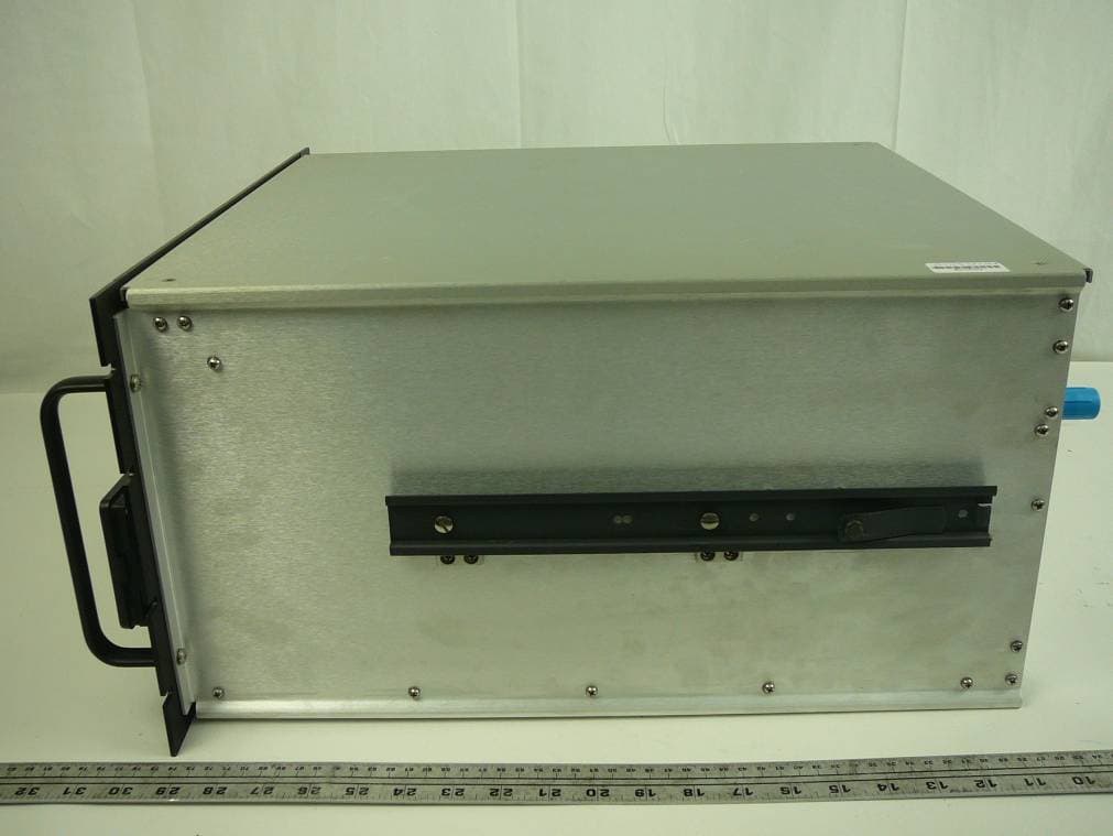
TCJ-M4DBDAV
Jun 23, 2011MARK-IV Digital Narrowband (Class-A) Signal Booster
Equipment Class
AMP - Amplifier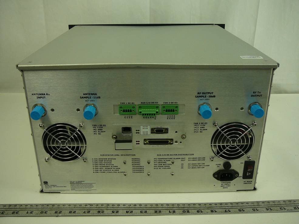
TCJ-M4DBDAU
Jun 16, 2011MARK-IV Digital Narrowband (Class-A) Signal Booster
Equipment Class
AMP - Amplifier
TCJ-M4BBDAU
Feb 13, 2006Power Amplifier
Equipment Class
AMP - Amplifier