TCJ-M4DBDAUMARK-IV Digital Narrowband (Class-A) Signal Booster
Canam Technology, Inc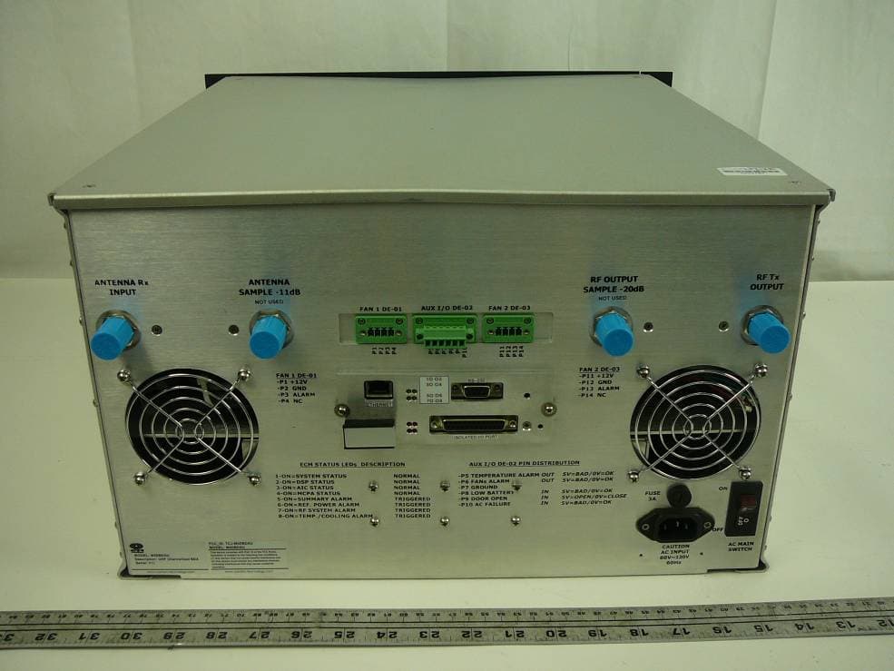
Click to zoom
Application Details
- Equipment Class
- AMP - Amplifier
- Date of Grant
- Jun 16, 2011
- Application Purpose
- Original Equipment
- Date of Application
- Jun 16, 2011
- Equipment Note
- MARK-IV Digital Narrowband (Class-A) Signal Booster
- Frequency Range
- 450.00000000 - 512.00000000
- Company
- Canam Technology, Inc
- Country
- United States
Documents & Files
Document Text
Text extracted from the exhibit documents filed with the FCC. Open a document above to read the original.
Users Manual
MARK-IV UHF NARROWBAND SIGNAL BOOSTER USER’S MANUAL REVISION 0 SUBMITTED BY: CANAM TECHNOLOGY, INC. May, 2011 CANAM TECHNOLOGY, INC. (CTI) MARK-IV UHF NARROWBAND SIGNAL BOOSTER USER’S MANUAL Page 2 of 12 Rev0 May/2011 I I . . T T A A B B L L E E O O F F C C O O N N T T E E N N T T S S I. TABLE OF CONTENTS ............................................................................................ 2 II. TABLE OF FIGURES ................................................................................................. 2 III. INTRODUCTION ..................................................................................................... 3 Section A. System Description ........................................................................... 3 IV. QUICK START ....................................................................................................... 5 Section A. Physical Overwiew ........................................................................... 5 Section B. Start - up............................................................................................. 7 B.1 Accessing D.U.T. Web Server .................................................................... 7 B.1.1 Connect D.U.T to P.C computer using a crossover cable ............... 7 B.1.2 Connect D.U.T to local area network .................................................. 8 B.2 Using and setting up D.U.T ......................................................................... 9 Section C. RF Connections ............................................................................... 11 C.1 Connecting the RF Out Port ................................................................... 11 C.2 Connecting the RF In Port ....................................................................... 11 I I I I . . T T A A B B L L E E O O F F F F I I G G U U R R E E S S Figure 1 – UHF Narrowband Signal Booster Basic Block Diagram ........................ 3 Figure 2 - Front Panel details ...................................................................................... 5 Table 1 – Front Panel details ...................................................................................... 5 Figure 3 - Rear Panel details. ..................................................................................... 6 Table 2 – Rear Panel details. ...................................................................................... 6 Figure 4 – D.U.T. connected directly to PC computer. .......................................... 7 Figure 5 - D.U.T. connected into local area network. ............................................ 8 Table 3 – Frequency ranges for filters ....................................................................... 9 Table 4 – Current programmed filter center frequencies ..................................... 9 CANAM TECHNOLOGY, INC. (CTI) MARK-IV UHF NARROWBAND SIGNAL BOOSTER USER’S MANUAL Page 3 of 12 Rev0 May/2011 I I I I I I . . I I N N T T R R O O D D U U C C T T I I O O N N Section A. System Description This system (D.U.T.) is an UHF Narrowband Signal Booster to operate within range 450-512MHz for Land Mobile radio FCC Part 90. Antenna Rx INPUT . . . RF Tx OUTPUT MCPA AGC AGC AGC Figure 1 – UHF Narrowband Signal Booster Basic Block Diagram The system features six or more programmable frequency narrowband filters. The desired operation frequencies must be configured using built-in Web Server. Programmable Individual Rx Threshold level (Squelch) per filter allows transmission if the probe signal is greater than configured Squelch. Individual Automatic Gain Control (AGC) per filter delivers constant output power level per channel (+/- 1 dB) regardless of their input level variations. The maximum output level per filter can be changed with option “Maximum Desired Output Level per filter” in Main Settings page from Web Server (please refer to UHF Narrow band Signal Booster O&M Manual.doc for more details). CANAM TECHNOLOGY, INC. (CTI) MARK-IV UHF NARROWBAND SIGNAL BOOSTER USER’S MANUAL Page 4 of 12 Rev0 May/2011 The built-in Web Server provides a Graphical User Interface (GUI) to ease in remote monitoring & control. Access is obtained via a PC’s Web Browser and a TCP/IP connection to the Unit. The system can be connected directly to a PC computer or can be plugged into the local area network. Some pages shown by the Web Server are the following: “Main Status”: depicts status alarm indicators and meters. “Main Settings”: is used to configure system-level macro settings. “Filter Settings” contains the settings that can be configured for each filter window. Never operate the system without adequate Load/Termination on the RF Tx Output. The UHF Narrowband Signal Booster will amplify until 120dB gain any input stimulus greater than Rx Threshold level (Squelch). The Web Server allows to Mute/Unmute Power Amplifier in “Main Settings” page. Make sure the power amplifier is unmuted before start with the test. CANAM TECHNOLOGY, INC. (CTI) MARK-IV UHF NARROWBAND SIGNAL BOOSTER USER’S MANUAL Page 5 of 12 Rev0 May/2011 I I V V . . Q Q U U I I C C K K S S T T A A R R T T Section A. Physical Overwiew Figure 2 shows the visual status that the D.U.T. front panel has. A brief explanation is given in Table 1. 231 4 5 6 7 Figure 2 - Front Panel details Table 1 – Front Panel details Item Description 1 Intake fan 1 2 LCD Display/Keypad 3 Intake fan 2 4 Power ON LED (Green = ok, Red = bad) 5 Summary Alarm LED (Green = ok, Red = bad) 6 Reflected Power Alarm LED (Green = ok, Red = bad) 7 Cooling Alarm LED (Green = ok, Red = bad) CANAM TECHNOLOGY, INC. (CTI) MARK-IV UHF NARROWBAND SIGNAL BOOSTER USER’S MANUAL Page 6 of 12 Rev0 May/2011 Figure 3 shows the connectors and visual status that the D.U.T rear panel has. A brief explanation of each connector is given in Table 2. 2146735 8 9 10 11 12 13 Figure 3 - Rear Panel details. Table 2 – Rear Panel details. Item Description 1 Antenna Rx Input 2 NOT USED 3 NOT USED 4 AUX Digital I/O Connecto…
Text truncated - open the document above for the full version.
External Photos
Canam Technology, Inc. FCC ID: TCJ-M4DBDAU Report Number: R1105232-90 Page 36 of 41 FCC Part 90 Test Report 14 Exhibit C - EUT Photographs 14.1 EUT - Top View 14.2 EUT - Front View Canam Technology, Inc. FCC ID: TCJ-M4DBDAU Report Number: R1105232-90 Page 37 of 41 FCC Part 90 Test Report 14.3 EUT - Rear View 14.4 EUT - Side View
ID Label/Location Info
MARK-IV UHF NARROWBAND SIGNAL BOOSTER MODEL: M4DBDAU FCC ID: TCJ- M4DBDAU REVISION 0 SUBMITTED BY: CANAM TECHNOLOGY, INC. May, 2011 CANAM TECHNOLOGY, INC. (CTI) MARK-IV UHF NARROWBAND SIGNAL BOOSTER Page 2 of 1 Rev0 May/2011 I I . . L L a a b b e e l l P P i i c c t t u u r r e e s s Figure 1 - Front Panel details Figure 2 – FCC ID Label design example NOTE: This is a FCC Label sample.
Internal Photos
Canam Technology, Inc. FCC ID: TCJ-M4DBDAU Report Number: R1105232-90 Page 38 of 41 FCC Part 90 Test Report 14.5 EUT – Cover off View 14.6 EUT – AIC Module Front View 14.7 EUT – AIC Module Back View Canam Technology, Inc. FCC ID: TCJ-M4DBDAU Report Number: R1105232-90 Page 39 of 41 FCC Part 90 Test Report 14.8 EUT – AIC Module Cover off View 14.9 EUT – DSP Module Front View 14.10 EUT – DSP Module Back View Canam Technology, Inc. FCC ID: TCJ-M4DBDAU Report Number: R1105232-90 Page 40 of 41 FCC Part 90 Test Report 14.11 EUT – DSP Module Cover off View 14.12 EUT –ECM Front View 14.13 EUT – ECM Back View Canam Technology, Inc. FCC ID: TCJ-M4DBDAU Report Number: R1105232-90 Page 41 of 41 FCC Part 90 Test Report 14.14 EUT –ECM Board Top View 14.15 EUT –ECM Board Bottom View ---End of Report---
Operational Description
MARK-IV UHF NARROWBAND SIGNAL BOOSTER OPERATIONS & MAINTENANCE (O&M) MANUAL REVISION 0 SUBMITTED BY: CANAM TECHNOLOGY, INC. June, 2011 CANAM TECHNOLOGY, INC. (CTI) MARK-IV UHF NARROWBAND SIGNAL BOOSTER OPERATIONS & MAINTENANCE (O&M) MANUAL Page 2 of 36 Rev0 June/2011 TABLE OF CONTENTS Section A. INTRODUCTION ..................................................................................... 4 Section B. GLOSSARY ............................................................................................. 6 Section C. SAFETY PRECAUTIONS .......................................................................... 7 C.1 Equipment Handling and Installation ......................................................... 7 C.2 Power Supplies ............................................................................................... 7 C.3 MCPA Modules ............................................................................................... 7 C.4 RF Exposure ..................................................................................................... 7 Section D. THEORY OF OPERATION ...................................................................... 9 D.1 Description ...................................................................................................... 9 D.2 Functional Block Diagram .......................................................................... 10 D.3 Features ......................................................................................................... 11 D.4 Specifications ............................................................................................... 12 D.5 FRONT AND REAR PANEL PORTS AND INTERFACES.................................. 14 D.6 LCD-Display & Keypad assembly .............................................................. 16 Section E. INITIAL CONFIGURATION ................................................................... 17 E.1 General guidelines regarding RF connections & operations with test instruments .............................................................................................................. 18 E.2 Antenna Installation .................................................................................... 19 Section F. WEB-SERVER GRAPHICAL USER INTERFACE .................................... 20 F.1 First-Time Start Configuration ...................................................................... 20 F.1.1 Connecting System directly to PC computer ...................................... 20 F.1.2 Connecting System to local area network .......................................... 26 F.2 Web Server Operations ............................................................................... 28 F.2.1 Main Status Page ...................................................................................... 28 F.2.2 Main Settings Page .................................................................................. 31 F.2.3 Filter Settings Page ................................................................................... 34 CANAM TECHNOLOGY, INC. (CTI) MARK-IV UHF NARROWBAND SIGNAL BOOSTER OPERATIONS & MAINTENANCE (O&M) MANUAL Page 3 of 36 Rev0 June/2011 TABLE OF FIGURES Figure 1 – MARK-IV UHF Narrowband Signal Booster General Block Diagram ............................. 10 Figure 2 – System Front-Panel ................................................................................................................. 14 Figure 3 - Rear Panel details. .................................................................................................................. 15 Figure 4 – LCD and Keypad Interface .................................................................................................. 16 Figure 5 – System connected directly to PC computer. ................................................................... 20 Figure 6 – Menu options for Local Area Connection. ....................................................................... 21 Figure 7 –Local Area Connection Properties. ..................................................................................... 22 Figure 8 – Internet Protocol (TCP/IP) Properties. ................................................................................. 23 Figure 9 –Local Area Connection Status. ............................................................................................ 24 Figure 10 –Local Area Connection Properties. ................................................................................... 25 Figure 11 – System connected into local area network. .................................................................. 26 Figure 12 – Main Status page ................................................................................................................. 28 Figure 13 – Main Settings page .............................................................................................................. 31 Figure 14 – Filter Settings page (1/2) ..................................................................................................... 34 Figure 15 – Filter Settings page (2/2) ..................................................................................................... 35 CANAM TECHNOLOGY, INC. (CTI) MARK-IV UHF NARROWBAND SIGNAL BOOSTER OPERATIONS & MAINTENANCE (O&M) MANUAL Page 4 of 36 Rev0 June/2011 Section A. INTRODUCTION The MARK-IV UHF Narrowband Signal Booster is a Class A Narrowband Signal Booster to operate within range 450-512MHz for Land Mobile radio FCC Part 90. This document is the MARK-IV UHF Narrowband Signal Booster Operations and Maintenance Manual, intended for the Radio Technical Personnel. This manual is intended to be used with the MARK-IV UHF Narrowband Signal Booster Equipment only. It is not to be used with any other equipment unless it is authorized by Canam Technology, Inc. Canam Technology, Inc provide this document “as is” without any warranty of any kind. Canam Technology may make chan…
Text truncated - open the document above for the full version.
RF Exposure Info
MARK-IV UHF NARROWBAND SIGNAL BOOSTER RF Exposure Information REVISION 0 SUBMITTED BY: CANAM TECHNOLOGY, INC. May, 2011 CANAM TECHNOLOGY, INC. (CTI) MARK-IV UHF NARROWBAND SIGNAL BOOSTER Page 2 of 3 Rev0 May/2011 RF Exposure recommendations The RF Field Strengths that an individual will be exposed to while doing maintenance is well below the limits set forth by the FCC & State Laws. Nevertheless, there are Safety Precautions that should be adhered when performing any RF Tests: 1. Never Operate a Transmitter, or Booster Amplifier without adequate Load/Termination on the Output Port. 2. Ensure all Connections are tight and secured. 3. Ensure all Coaxial Cable Insulation covers the Outer Shield of the cable. 4. Do Not Touch Exposed System Ports or Coaxial Cable if system is Transmitting. 38 RF Signs Sign Examples CANAM TECHNOLOGY, INC. (CTI) MARK-IV UHF NARROWBAND SIGNAL BOOSTER Page 3 of 3 Rev0 May/2011 Maximum Antenna Gain The Input antenna and output antenna are not included with this equipment. Nevertheless, if this device is used in an application that requires direct connection to an antenna, Canam Technology recommends following the FCC guidelines for its installation. According to FCC rule § 1.1310 Radiofrequency radiation exposure limits the limits for maximum permissible exposure (MPE) are as follow: Table 1 – Limits for maximum permissible exposure (MPE) Frequency range (MHz) Power density (mW/cm 2 ) Occupational Controlled Exposures 300-1500 f/300 General Population Uncontrolled Exposure 300-1500 f/1500 The Maximum antenna gain is determined using the Friis transmission equation: where: = Power density (mW/cm2). = Output power (mW). = Antenna gain (linear scale). = Distance between observation point and center of the radiator in cm The calculated Antenna Gain for r = 100cm the maximum permissible exposure (MPE) is shown in Table 2. Table 2 – Limits for maximum permissible exposure (MPE) Frequency (MHz) Maximum Antenna Gain (dBi) Occupational Controlled Exposures 480 16.04 General Population Uncontrolled Exposure 480 9.053 Antenna Installation should be performed by qualified technical personnel. The installations instructions are for the purpose of complying with FCC RF Exposure and are not optional. All antennas should be fixed mounted and physically secured to one location. Non-building mounted donor antennas must be greater than 10 meters above ground. CANAM TECHNOLOGY, INC. (CTI) MARK-IV UHF NARROWBAND SIGNAL BOOSTER Page 4 of 3 Rev0 May/2011 (This Page was intentionally left blank)
Test Report
Note: This test report is prepared for the customer shown above and for the device described herein. It may not be duplicated or used in part without prior written consent from Bay Area Compliance Laboratories Corp. This report must not be used by the customer to claim product certification, approval, or endorsement by NVLAP*, NIST, or any agency of the Federal Government. * This report may contain data that are not covered by the NVLAP accreditation and are marked with an asterisk “*” (Rev.2) FCC PART 90 TEST AND MEASUREMENT REPORT For Canam Technology Inc. 5318 East 2 nd Street #700, Long Beach, CA, 90803, USA FCC ID: TCJ-M4DBDAU Report Type: Original Report Product Type: UHF Amplifier Test Engineer: Kevin Li Report Number: R1105232-90 Report Date: 2011-06-14 Reviewed By: Victor Zhang EMC/RF Lead Prepared By: (84) Bay Area Compliance Laboratories Corp. 1274 Anvilwood Avenue, Sunnyvale, CA 94089, USA Tel: (408) 732-9162 Fax: (408) 732 9164 Canam Technology, Inc. FCC ID: TCJ-M4DBDAU Report Number: R1105232-90 Page 2 of 41 FCC Part 90 Test Report TABLE OF CONTENTS 1 GENERAL INFORMATION.............................................................................................................................. 5 1.1 PRODUCT DESCRIPTION FOR EQUIPMENT UNDER TEST (EUT) ........................................................................ 5 1.2 MECHANICAL DESCRIPTION OF EUT............................................................................................................... 5 1.3 OBJECTIVE...................................................................................................................................................... 5 1.4 RELATED SUBMITTAL(S)/GRANT(S) ................................................................................................................ 5 1.5 TEST METHODOLOGY...................................................................................................................................... 5 1.6 MEASUREMENT UNCERTAINTY....................................................................................................................... 6 1.7 TEST FACILITY................................................................................................................................................ 6 2 SYSTEM TEST CONFIGURATION ................................................................................................................. 7 2.1 JUSTIFICATION................................................................................................................................................. 7 2.2 EUT EXERCISE SOFTWARE............................................................................................................................. 7 2.3 EQUIPMENT MODIFICATIONS........................................................................................................................... 7 2.4 SPECIAL EQUIPMENT....................................................................................................................................... 7 2.5 LOCAL SUPPORT EQUIPMENT.......................................................................................................................... 7 2.6 EUT INTERNAL CONFIGURATION DETAILS..................................................................................................... 7 2.7 EXTERNAL I/O CABLING LIST AND DETAILS................................................................................................... 7 3 SUMMARY OF TEST RESULTS ...................................................................................................................... 8 4 FCC §2.1046 & §90.205 – RF OUTPUT POWER ............................................................................................. 9 4.1 APPLICABLE STANDARDS................................................................................................................................9 4.2 TEST PROCEDURE............................................................................................................................................ 9 4.3 TEST SETUP BLOCK DIAGRAM........................................................................................................................ 9 4.4 TEST EQUIPMENT LIST AND DETAILS.............................................................................................................. 9 4.5 TEST ENVIRONMENTAL CONDITIONS............................................................................................................ 10 4.6 TEST RESULTS............................................................................................................................................... 10 5 FCC §2.1047 - MODULATION CHARACTERISTIC ................................................................................... 11 5.1 APPLICABLE STANDARD................................................................................................................................11 5.2 TEST RESULT................................................................................................................................................. 11 6 FCC §90.209 – 99% & 26 DB EMISSION BANDWIDTH ............................................................................. 12 6.1 APPLICABLE STANDARD................................................................................................................................12 6.2 TEST PROCEDURE.......................................................................................................................................... 12 6.3 TEST ENVIRONMENTAL CONDITIONS............................................................................................................ 12 6.4 TEST EQUIPMENT LIST AND DETAILS............................................................................................................ 12 6.5 TEST RESULTS.............................................................................................…
Text truncated - open the document above for the full version.
Test Setup Photos
Canam Technology, Inc. FCC ID: TCJ-M4DBDAU Report Number: R1105232-90 Page 34 of 41 FCC Part 90 Test Report 13 Exhibit B - Test Setup Photographs 13.1 Radiated Emissions - Front View 13.2 Radiated Emissions - Rear View (Below 1 GHz) Canam Technology, Inc. FCC ID: TCJ-M4DBDAU Report Number: R1105232-90 Page 35 of 41 FCC Part 90 Test Report 13.3 Radiated Emissions - Front View (Above 1 GHz)
Contact Information
Applicant
Victor J. Bermudez
Test Firm
Bay Area Compliance Laboratories Corp.Kaveh Moraghebi
Technical Specifications
| # | Rule Parts | Frequency Range | Power Output | Emission | Tolerance |
|---|---|---|---|---|---|
| 1 | 90 | 450 MHz - 512 MHz | 5 W | NOTE 1 | Amp |
Other Applications from Canam Technology, Inc
TCJ-M4BBDAUU
Apr 21, 2026Bi Directional Amplifier
Equipment Class
B9B - Part 90 Class B Industrial Booster (non-SMR)
TCJ-M4BBDAV
Jul 14, 2015MARK-IV Broadband (Class-B) Signal Booster
Equipment Class
B9B - Part 90 Class B Industrial Booster (non-SMR)
TCJ-M4DBDA7
Sep 17, 2012MARK-IV Digital Narrowband (Class-A) Signal Booster
Equipment Class
TNB - Licensed Non-Broadcast Station Transmitter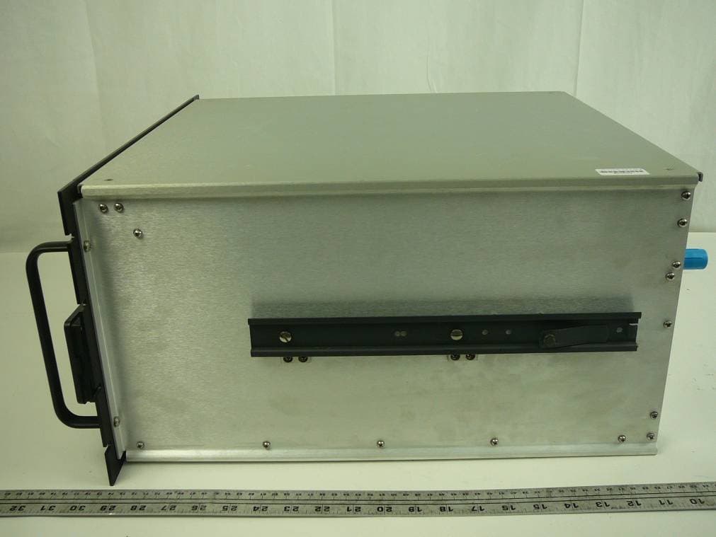
TCJ-M4DBDAV
Jun 23, 2011MARK-IV Digital Narrowband (Class-A) Signal Booster
Equipment Class
AMP - Amplifier
TCJ-M4BBDAU
Feb 13, 2006Power Amplifier
Equipment Class
AMP - Amplifier