TCJM4-CHOLC-800ULMark IV Class A Narrowband Signal Booster
Canam Technology, Inc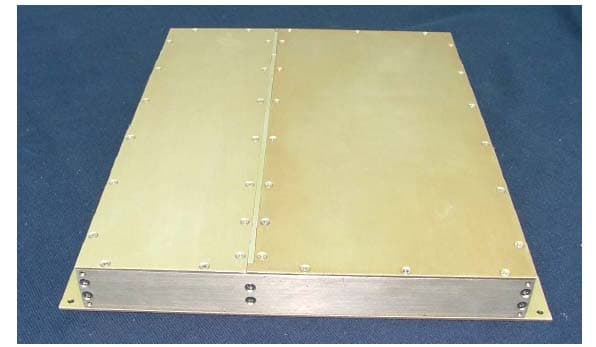
Click to zoom
Application Details
- Equipment Class
- AMP - Amplifier
- Date of Grant
- Jul 04, 2005
- Application Purpose
- Original Equipment
- Date of Application
- Jul 04, 2005
- Equipment Note
- Mark IV Class A Narrowband Signal Booster
- Frequency Range
- 806.00000000 - 824.00000000
- Company
- Canam Technology, Inc
- Country
- United States
Documents & Files
Document Text
Text extracted from the exhibit documents filed with the FCC. Open a document above to read the original.
Users Manual
MARK-IV CHANNELIZED RADIO REBROADCAST SYSTEM MARK-IV NARROWBAND (CHANNELIZED) CLASS A SIGNAL BOOSTER WITH AUTOMATIC OUTPUT LEVEL CONTROL M4-ChOLC USER’S OPERATION & MAINTENANCE MANUAL PRELIMINARY SUBMITTED BY: CANAM TECHNOLOGY, INC. April 2005 Canam Technology, Inc. (CTI) MARK-IV CHANNELIZED (Class A Narrowband) SIGNAL BOOSTER WITH AUTOMATIC OUTPUT LEVEL CONTROL M4-ChOLC User’s Operations and Maintenance Manual (O&M) I I . . T T A A B B L L E E O O F F C C O O N N T T E E N N T T S S Section A. Introduction............................................................................................ 3 Section B. GLOSSARY OF TERMS ............................................................................ 4 Section C. THEORY OF OPERATION ........................................................................ 5 C.1 DESCRIPTION.................................................................................................. 5 C.2 FEATURES & APPLICATIONS .......................................................................... 6 C.3 INPUT (Rx) INTERMODULATION REJECTION ................................................ 7 C.4 THE CHANNEL PROCESSOR.......................................................................... 7 C.5 CHANNEL SELECTIVITY.................................................................................. 8 C.6 MARK-IV MODULE SPECIFICATIONS............................................................ 9 Section D. INSTALLATION ....................................................................................... 10 D.1 Equipment Installation ............................................................................... 10 D.2 Antenna Installation ...................................................................................11 Section E. OPERATION........................................................................................... 12 Section F. M4-ChOLC Adjustments..................................................................... 13 F.1 M4-ChOLC Channel Frequency Programming ..................................... 13 F.2 M4-ChOLC Output Level ........................................................................... 15 F.3 M4-ChOLC RX Threshold Level ................................................................. 16 F.4 M4-ChOLC Status and Alarms .................................................................. 16 Section G. TROUBLESHOOTING ......................................................................... 18 G.1 DC POWER ALARM ..................................................................................... 18 G.2 RF STATUS ALARM ........................................................................................ 18 G.3 COM PORT ................................................................................................... 18 MARK-IV CHANNELIZED Signal Booster module (M4-ChOLC) O&M Manual Page 2 of 20 Canam Technology, Inc. (CTI) MARK-IV CHANNELIZED (Class A Narrowband) SIGNAL BOOSTER WITH AUTOMATIC OUTPUT LEVEL CONTROL M4-ChOLC User’s Operations and Maintenance Manual (O&M) I I I I . . U U S S E E R R ’ ’ S S O O P P E E R R A A T T I I O O N N S S & & M M A A I I N N T T E E N N A A N N C C E E Section A. Introduction The MARK-IV is a Class A Narrowband (Channelized) Signal Booster module equipped with automatic Output Level Control (ChOLC), for operation under FCC Part 90.219 in the frequency bands of VHF, UHF and 800 MHz. The MARK-IV module could also be used to retrofit Class B Broadband Bi-directional Amplifiers (BDAs), converting them into Class A Narrowband (Channelized) Boosters compliant with the FCC Part 90.219(d) requirements to transmit outdoors. M4-ChOLC Key Features: • Narrowband Class A Signal Booster, per FCC Part 90.219 and 90.7 • Maximum Output Power = 0 dBm. • Out-of-Band emissions < –13 dBm, compliant with FCC requirements. • AGC circuit provides a constant output power, regardless of the input power. This document is the MARK-IV module Operations and Maintenance Manual, intended for the Radio Technical Personnel. It contains detailed descriptions of each one of the M4-ChOLC subsystems down to their Lowest Replaceable Units (LRU). This manual is intended to be used with the M4-ChOLC Equipment only. It is not to be used with any other equipment unless it is authorized by Canam Technology, Inc. Canam Technology, Inc provide this document “as is” without any warranty of any kind. This document may contain typographical errors and technical inaccuracies. Canam Technology will not accept any liability from the use and misuse of this manual, the information contained within, or the consequences of any actions resulting from the use of this information. The user can not make any modifications to the unit(s). Changes or modifications not expressly approved by the party responsible for compliance voids the user’s authority to operate the equipment. Signal boosters such as the M4-ChOLC generate radio signals and, therefore, electromagnetic fields. The technical personnel should have a complete understanding of FCC CFR Title 47 sections 1.1307 and 1.1310. Recommendations are included in this Manual, but they do not substitute the FCC guidelines. This device may require the use of antennas for proper functioning, depending on the application. The installation of the antennas should be performed by qualified technical personnel. All antennas should be fixed mounted and physically secured to one location. The people must be away from the antennas at least 0.25 meters to comply with the RF Human Maximum Permissible Exposure limits, as long as the antenna system gain is lower than 33 dBi. If greater gain is used the separation should be increased, please refer to the FCC Rules. If service should be performed on the antenna, please shut down the transmitter or lower its power in order to comply with the maximum permissible exposure. MARK-IV CHANNELIZED Signal Booster module (M4-ChOLC) O&M Manual Page 3 of 20 Canam Technology, Inc. (CT…
Text truncated - open the document above for the full version.
External Photos
APPENDIX C - EUT EXTERNAL PHOTOGRAPHS EUT – Front View EUT – Rear View EUT – Top View EUT – Bottom View
ID Label/Location Info
APPENDIX A - FCC ID LABELING AND LOCATION Proposed FCC ID Labeling Proposed FCC ID Location Rear Side of EUT / Proposed Label Location
Internal Photos
APPENDIX C - EUT INTERNAL PHOTOGRAPHS EUT – Cover Off View With Shields EUT - Cover Off View Without Shields PCB # 1 – Component View PCB # 1 – Solder View PCB # 2 – Component View PCB # 2 – Solder View
Operational Description
Canam Technology, Inc. (CTI) MARK-IV CHANNELIZED (Class A Narrowband) SIGNAL BOOSTER WITH AUTOMATIC OUTPUT LEVEL CONTROL M4-ChOLC Datasheet MARK-IV CHANNELIZED Signal Booster module (M4-ChOLC) Datasheet Page 1 of 5 A.1 DESCRIPTION The CTI MARK-IV CHANNELIZED REBROADCAST SYSTEM is designed for multi-carrier two-way rebroadcast systems, where significantly high dynamic range is required. The M4-ChOLC is a Narrowband Class A (Channelized or Channel Selective) Signal Booster with a 100 dB Automatic Output Level Control, fully compliant with the FCC requirements to transmit signals outdoors back to the donor sites or basestations. Per FCC 90.219(d) only narrowband (class A) signal boosters can be used for that application, the broadband BDAs are not allowed to transmit outdoors. INPUT SPLITTER OUTPUT COMBINER RF INPUT SIGNAL RF OUTPUT SIGNAL CH-1 OLC CH-2 OLC CH-n OLC It can also be used as a front-end filter system to retrofit Broadband BiDirectional Amplifiers (BDAs). Figure 1: Channelized Rebroadcast System When several M4-ChOLC modules are combined to process multiple channels within a desired band, the RF signals going into the BDA are set at a constant level by the 100 dB Automatic Output Level Control, regardless of their input level, which significantly improves the system dynamic range. The M4-ChOLC modules reduce high power carriers that can saturate the BDAs and create Intermodulation (IM) Products in the system. On the other hand, the M4-ChOLC modules boost up weak carriers that would be otherwise lost in a broadband BDA system. See next Figure 2. The M4-ChOLC modules turn a Broadband BDA into a Narrowband Class A “channelized BDA” that can be used to transmit signals outdoors, without the limitations set forth by the FCC in Part 90.219(d). M4-ChOLC modules can be programmed for processing any communications channel in the two-way mobile radio UHF or 800 MHz SMR bands, while maintaining system flexibility. Multiple modules are combined into a single output signal with Low-Level passive combining, which improves BDA efficiency and cost effectiveness by reducing combiner costs. The M4-ChOLC modules are a very cost-effective upgrade to existing BDA systems that both improves their performance and makes them compliant with FCC 90-219(d). Figure 2 shows, as example, the operation of an integrated system with only four M4-ChOLCs programmed on F1, F3, F0 and F5 frequencies. The signals on F2, F4 and F6 are filtered out, since there are no M4-ChOLCs tuned to them. Canam Technology, Inc. (CTI) MARK-IV CHANNELIZED (Class A Narrowband) SIGNAL BOOSTER WITH AUTOMATIC OUTPUT LEVEL CONTROL M4-ChOLC Datasheet MARK-IV CHANNELIZED Signal Booster module (M4-ChOLC) Datasheet Page 2 of 5 -100 -90 -80 -70 -60 -50 -40 -30 -20 -10 0 Level dBm f 1 FREQ MHz f 2 f 3 f 0 f 4 f 5 f 6 -100 -90 -80 -70 -60 -50 -40 -30 -20 -10 0 Level dBm f 1 FREQ MHz f 2 f 3 f 0 f 4 f 5 f 6 INPUT SPECTRUMOUTPUT SPECTRUM Figure 2: 4-channels Integrated System Input and Output Spectrum A.2 FEATURES & APPLICATIONS • M4-ChOLC modules are a front-end Channelized Signal Conditioner System (Channel Selective, class A narrowband signal boosters per FCC definition) that effectively and efficiently converts broadband BDAs into Channelized Class A boosters compliant with FCC 90.219(d) rule. • M4-ChOLC modules, Higher Input Dynamic Range, reduce the impact of strong interfering input carriers (those that create 3 rd order IM products landing right on another system desired channel). Two interfering carriers could be up to -30 dBm at the module’s input without causing harmful interference in the desired channel. • M4-ChOLC modules, Higher Input (Rx) Intermodulation Rejection, -30 dBm maximum input for two undesired carriers causing 3 rd order IM interference. • M4-ChOLC modules, 100 dB Automatic Output Level Control equalizes the output signal at a fixed level regardless of the input level = improves the system dynamic range to feed RF-over-Fiber optic links or remote boosters with constant levels to overcome the link losses and the RF/Optic converter’s very high noise figures. • M4-ChOLC modules Frequency and Phase Tracking follow exactly the input signal’s frequency and modulation (analog or digital), with minimum delay. • M4-ChOLC modules are Field-programmable Operating Frequency = PLL-based Synthesizer. • M4-ChOLC module Manual Input (Rx) Threshold and Output Power Level controls provide easy field adjustments and Status Indicators (visual LED and Discrete Signals). • M4-ChOLC modules, Small Foot-print & Simple Installation, • M4-ChOLC stand-alone modules require only +15 VDC. Canam Technology, Inc. (CTI) MARK-IV CHANNELIZED (Class A Narrowband) SIGNAL BOOSTER WITH AUTOMATIC OUTPUT LEVEL CONTROL M4-ChOLC Datasheet MARK-IV CHANNELIZED Signal Booster module (M4-ChOLC) Datasheet Page 3 of 5 A.3 INPUT (Rx) INTERMODULATION REJECTION The M4-ChOLC delivers an outstanding Input (Rx) Intermodulation Rejection, which combined with its Input Sensitivity of -100 dBm allows the module to tolerate strong undesired input carriers of up to -30 dBm with no interference on the desired channel, as per TIA standards. Figure 3 illustrates this case’s input spectrum. This is particularly important for critical applications where the frequency plan contains channels that would create 3 rd and 5 th order Intermodulation Products landing in-band right on other desired system channel(s), since two or more very strong signals at F 1 and F 2 frequencies impacting the M4- ChOLC’s front-end would cause interference on the desired F 0 channel. A.4 THE CHANNEL PROCESSOR The architecture of the M4-ChOLC is based on down&up heterodyne frequency converters, featuring narrowband Intermediate Frequency (IF) filters and Automatic Gain Control signal conditioner. The output signal reproduces the exact input’s frequency and modulation (analog or digital), as received at the module’s input. The next diagram in Figure 4 shows the simplified M4-ChOLC architecture. Figure 3: Inp…
Text truncated - open the document above for the full version.
Test Report
Note: The test report is specially limited to the above company and this particular sample only. It may not be duplicated without prior written consent of Bay Area Compliance Laboratory Corporation. This report must not be used by the client to claim product certification, approval, or endorsement by NVLAP, NIST or any agency of the US Government. FCC PART 90 TYPE APPROVAL EMI MEASUREMENT AND TEST REPORT For CANAM TECHNOLOGY, INC. 5318 East 2 nd Street #700 Long Beach, CA90803 FCC ID: TCJM4-CHOLC-800UL This Report Concerns: Original Report Equipment Type: Signal Booster Test Engineer: Daniel Deng Report No.: R0506021 Report Date: 2005-06-12 Reviewed By: Richard Lee Prepared By: Bay Area Compliance Laboratory Corporation 230 Commercial Street Sunnyvale, CA 94085 Tel: (408) 732-9162 Fax: (408) 732 9164 Canam Technology, Inc. FCC ID: TCJM4-CHOLC-800UL Report # R0506021Rpt-a Page 2 of 21 FCC Part 90 Type Approval Report TABLE OF CONTENTS GENERAL INFORMATION.......................................................................................................................................3 PRODUCT DESCRIPTION FOR EQUIPMENT UNDER TEST (EUT) ....................................................................................3 OBJECTIVE...................................................................................................................................................................3 RELATED SUBMITTAL(S)/GRANT(S).............................................................................................................................3 TEST METHODOLOGY..................................................................................................................................................3 TEST FACILITY.............................................................................................................................................................3 SYSTEM TEST CONFIGURATION ..........................................................................................................................5 JUSTIFICATION.............................................................................................................................................................5 BLOCK DIAGRAM.........................................................................................................................................................5 EQUIPMENT MODIFICATIONS.......................................................................................................................................5 LOCAL SUPPORT EQUIPMENT.......................................................................................................................................5 INTERFACE PORTS AND CABLING.................................................................................................................................5 CONFIGURATION OF TEST SYSTEM..............................................................................................................................6 TEST SETUP BLOCK DIAGRAM.....................................................................................................................................6 SUMMARY OF TEST RESULTS ...............................................................................................................................7 §2.1046 AND §90.219 – CONDUCTED OUTPUT POWER......................................................................................8 PROVISION APPLICABLE...............................................................................................................................................8 TEST EQUIPMENT LIST AND DETAILS...........................................................................................................................8 ENVIRONMENTAL CONDITIONS....................................................................................................................................8 TEST RESULTS.............................................................................................................................................................8 §2.1049, AND § 90.209 – OCCUPIED BANDWIDTH ...............................................................................................9 APPLICABLE STANDARD..............................................................................................................................................9 TEST PROCEDURE........................................................................................................................................................9 TEST EQUIPMENT.........................................................................................................................................................9 ENVIRONMENTAL CONDITIONS....................................................................................................................................9 TEST RESULTS.............................................................................................................................................................9 §2.1051 AND §90.210 - SPURIOUS EMISSIONS AT ANTENNA TERMINALS ................................................11 APPLICABLE STANDARD............................................................................................................................................11 TEST PROCEDURE......................................................................................................................................................11 TEST EQUIPMENT.......................................................................................................................................................11 ENVIRONMENTAL CONDITIONS..................................................................................................................................11 TEST RESULTS...............................................................................................................................…
Text truncated - open the document above for the full version.
Contact Information
Applicant
Victor J. Bermudez
Test Firm
Bay Area Compliance LaboratoryJohn Chan
Technical Specifications
| # | Rule Parts | Frequency Range | Power Output | Emission |
|---|---|---|---|---|
| 2 | 9 | 806 MHz - 824 MHz | 1.00 mW | 12K5F1D |
Other Applications from Canam Technology, Inc
TCJ-M4BBDAUU
Apr 21, 2026Bi Directional Amplifier
Equipment Class
B9B - Part 90 Class B Industrial Booster (non-SMR)
TCJ-M4BBDAV
Jul 14, 2015MARK-IV Broadband (Class-B) Signal Booster
Equipment Class
B9B - Part 90 Class B Industrial Booster (non-SMR)
TCJ-M4DBDA7
Sep 17, 2012MARK-IV Digital Narrowband (Class-A) Signal Booster
Equipment Class
TNB - Licensed Non-Broadcast Station Transmitter
TCJ-M4DBDAV
Jun 23, 2011MARK-IV Digital Narrowband (Class-A) Signal Booster
Equipment Class
AMP - Amplifier
TCJ-M4DBDAU
Jun 16, 2011MARK-IV Digital Narrowband (Class-A) Signal Booster
Equipment Class
AMP - Amplifier