TCORT5022VHF Marine Radiotelephone
Thrane & Thrane A/S
Click to zoom
Application Details
- Equipment Class
- GVH - Part 80 VHF Transmitter (GMDSS)
- Date of Grant
- Jun 28, 2005
- Application Purpose
- Original Equipment
- Date of Application
- Jun 28, 2005
- Equipment Note
- VHF Marine Radiotelephone
- Frequency Range
- 149.30000000 - 163.75000000
- Company
- Thrane & Thrane A/S
- Country
- Denmark
Documents & Files
Document Text
Text extracted from the exhibit documents filed with the FCC. Open a document above to read the original.
Users Manual
SAILOR RT5022 VHF DSC Operation Manual PRELIMINARY ii Introduction Congratulations on your new SAILOR RT5022 VHF SAILOR marine equipment is specially designed for the extremely rugged conditions on bord a ship, based on more than 50 years experience with all kinds of vessels , from small pleasure crafts, over fishing vessels working under all climatic conditions, to the biggest ships. SAILOR ® is one of Europe’s leading manufacturers of maritime radiocommunication equipment - a position which has been maintained by means of constant and extensive product development. We have a worldwide network of dealers with general agencies in more than 80 countries. All our dealers are specially trained to service all your SAILOR ® products. About this manual This manual is for the daily user of the system. Additionally, it includes a section on the installation procedures, and - on page ii - standard distress procedures. We highly recom- mend you to read the manual before you start using the equipment. Notice: There may be some minor differences in the graphic layout of the manual compared to the physical device. Abbreviations used in this manual ADDRAddress BIChannel mode when sailing on European rivers BQDSC Call Acknowledgement Reply CUControl Unit DSCDigital Selective Calling DWDual Watch EOSDSC End Of Sequence GMDSSGlobal Maritime Distress and Safety System MMSIMaritime Mobile Service Identification PTT“Push To Talk” button RQDSC Call Acknowledgement Request RXReceive/r SQSquelch TXTransmit/ter UTCCoordinated Universal Time Please note Any responsibility or liability for loss or damage in connection with the use of this product and the accompanying documentation is disclaimed. The information in this manual is furnished for informational use only, is subject to change without notice, may contain errors or inaccuracies, and represents no commitment whatsoever. This agreement is governed by the laws of Denmark. Doc. No.: B5022GB0Issue: PRELIMINARY, 0505 iii QUICK DSC DISTRESS CALL (only for emergency use) 1. If necessary, switch on by pressing the ON/OFF button. 2. Lift up lid covering the orange DISTRESS key and press for 5 seconds. 3.Alarm indicator light will flash and will be accompanied by a sound. Distress is sent after continuous tone. 4. Unless stopped manually, by pressing the key or switching the unit off, the distress call is automatically repeated every 3½-4½ min- utes until distress acknowledgment is received. Wait for distress acknowledgement and start mayday procedure. If an alarm panel is connected the VHF DISTRESS button on this unit will have the same functionality. All further handling should continue in front of your main VHF DSC. MAYDAY PROCEDURE When DSC distress acknowledgement is received after you pushed DISTRESS, or if you otherwise need to commence distress traffic by radiotelephony on the distress traffic frequency channel 16, this should follow: •“MAYDAY”, •“this is”, •the 9-digit identity and the call sign or other identification of the ship, •the ship’s position in latitude and longitude or other reference to a known geographical location, •the nature of distress and assistance wanted, •any other information which might facilitate the rescue. Upon reception of a DSC distress alert from another ship in distress, you should acknowledge the receipt by radiotelephony on the distress traffic frequency channel 16, with the following: •“MAYDAY”, •the 9-digit identity of the ship in distress, repeated 3 times, “this is”, •the 9-digit identity or the call sign or other identification of own ship, repeated 3 times, •“RECEIVED MAYDAY”. vi 0131 Your VHF at a glance 1. Loudspeaker 2. Volume level indicator 3. Squelsh level indicator 4. Indicator lamps. Condition when lit: 1W: 1 watt transmission mode. Alarm: Alarm call received. Call: DSC call for you received. DW: 5. Telephone display 6. Indicators. Condition when lit: Tx: Transmitting Int: International channel system activated (Is used when sailing on any sea in the world except in US waters) US: US channel system activated (Is used when sailing in US Waters) BI: BI channel system activated (Is used when sailing on the rivers of Europe) 1 2 3 4 5 678910 111213141516 Int US BI Tx Call DW 1W Vol SQ Alarm 0191 - 05 7. Dimming button 8. Menu button 9. Mute alerts 10. Keyboard. 11. DISTRESS button (Lid with spring. Normal push button underneath) 12. Information/Message display 13. Squelsh control. Adjust to silent when no station is received 14. Push ON/OFF / VOLUME control 15. Replay button 16. Quick-select key for channel 16. 1 0505 Contents Introduction.............................................................................................................................. ii About this manual................................................................................................................ ii Abbreviations used in this manual...................................................................................... ii QUICK DSC DISTRESS CALL................................................................................................ iii MAYDAY PROCEDURE........................................................................................................... iii Your VHF at a glance............................................................................................................... iv 1Radio Communication in brief......................................................................................... 3 1.1 Powering VHF............................................................................................................. 3 1.2 Operating VHF radio communication......................................................................... 3 1.3 Receiving a Call on Channel 16................................................................................. 3 1.4 Making a Radiotelephone Call................................................................................... 4 1.5 Speaker Volume.............…
Text truncated - open the document above for the full version.
Users Manual
Thrane & Thrane A/S · Porsvej 2 · P.O. Box 7071 · DK-9200 Aalborg SV · Denmark T +45 39 55 88 00 · F +45 39 55 88 88 · [email protected] · www.thrane.com Bank: Danske Bank · Comp.reg.: 65 72 46 18 · VAT: DK-20 64 64 461/2 Training Information This Thrane&Thrane radio RT5022 is designed for and classified as “occupational use only”. It must only be used in the course of employment by individuals aware of both the hazard and the ways to minimize those hazards. This radio is NOT intended for use in an uncontrolled environment by the “General Population”. This radio has been tested and complies with the FCC RF exposure limits for “Occupational Use Only”. This VHF radio also complies with the following guidelines and standard regarding RF energy and electromagnetic energy levels as well as evaluation of those levels for human exposure: FCC OET Bulletin 65 Supplement C, evaluating compliance with FCC guidelines for human exposure to radio frequency electromagnetic fields. American National Standards Institute (C95.1) IEEE standard for safety levels with respect to human exposure to radio frequency electromagnetic fields, 3 kHz to 300 GHz. American National Standards Institute (C95.3) IEEE recommended practice for the measurement of potentially hazardous electromagnetic fields – RF and microwaves. The following warnings and cautions will make you aware of RF exposure hazards and how to assure you operate the radio within the FCC RF exposure limits established for it. Warning: Your Thrane&Thrane radio generates electromagnetic RF (radio frequency) energy when it is transmitting. To ensure that you and those around you are not exposed to excessive amounts of that energy (beyond FCC allowable limits for occupational use): To avoid health hazards from excessive exposure to RF energy, FCC OET Buletin 65 establishes an MPE radius of 10’ (3m) for the maximum power of your radio (25W selected) with an antenna having a maximum power gain of 9dBi. This means that all persons must be at least 10’ (3m) away from the antenna when the radio is transmitting. Installation: 1) An omnidirectional antenna with with a gain not greater than 9dBi must be mounted atleast 16.4’ (5m) above the highest deck where people may be during radio transmissions, measured vertically from the lowest point of the antenna. This provides the minimum separation distance to comply with RF exposure requirements and is based on the MPE radius of 10’ (3m) plus the 6.6’ (2m) height of an adult. 2) For vessels which cannot fulfil requirements in 1) it must be mounted as follows and all persons must be outside the 10’ (3m) MPE radius during radio transmissions. The antenna must Thrane & Thrane A/S · Porsvej 2 · P.O. Box 7071 · DK-9200 Aalborg SV · Denmark T +45 39 55 88 00 · F +45 39 55 88 88 · [email protected] · www.thrane.com Bank: Danske Bank · Comp.reg.: 65 72 46 18 · VAT: DK-20 64 64 462/2 be mounted so that its lowest point is at least 3,3’ (1m) vertically above the heads of all persons during radio transmissions. - Always mount the antenna at least 10’ (3m) from possible human access; - Never touch the antenna when transmitting; - Use only authorized T&T accessories; Failure to observe any of these warnings may cause you to exceed FCC RF exposure limits or create other dangerous conditions.
Attestation Statements
Doc. no 40049A00 To: Federal Communications CommissionAalborg, 07.07-2005 Regarding FFC ID: TCORT5022 Attestation Statement Thrane & Thrane A/S being the applicant attest the equipment complies with performance standards as specified in 80.1101 and where applicable, measurements have been made that demonstrate the necessary compliance. Yours sincerely Chief Executive Officer Peter Høy
External Photos
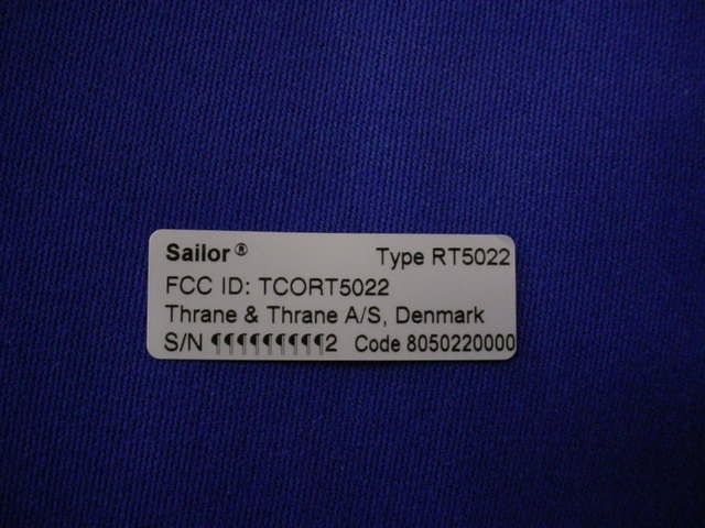
Sailor Maritime VHF radio telephone RT5022 RT5022 EXTERNAL PICTURES Front view with handset HS 5001. VHF mounted in bracket 1/4 Type label with FCC ID Location of type label at lower right corner 2/4 Keyboard and Display front view 3/4 Rear view 4/4
Internal Photos
Sailor Maritime VHF radio telephone RT5022 RT5022 INTERNAL PICTURES RF module 639120, upper layer 1/8 RF module 639120, lower layer 2/8 Base Band module 639110, upper layer 3/8 Base Band module 639110, lower layer 4/8 Keyboard / Display module 639130, upper layer Keyboard / Display module 639130, lower layer 5/8 Cover removed to Base band with rf screen. Keyboard/display at left. Loudspeaker at upper left corner. Power supply module in metal box at bottom 6/8 Cover removed to Rf module with Rf screen 7/8 Power supply module, upper layer Power supply module, lower layer 8/8
Test Report
Test report 99608331 based on: FCC Part 80 (10-1-04 Edition) Maritime shipborne VHF radio telephone with integrated DSC class A controller and channel 70 watchkeeping receiver SAILOR RT5022 Report number: 99608331 Contents MAIN MODULE.......................................................................................................................................................3 1 I NTRODUCTION ...............................................................................................................................................3 2 P RODUCT ........................................................................................................................................................4 3 T EST SCHEDULE ..............................................................................................................................................4 4 P RODUCT DOCUMENTATION ............................................................................................................................5 5 O BSERVATIONS AND COMMENTS .....................................................................................................................5 6 S UMMARY .......................................................................................................................................................5 7 C ONCLUSIONS .................................................................................................................................................6 TEST RESULTS MODULE.....................................................................................................................................7 1 S UMMARY .......................................................................................................................................................8 2 E MISSION TESTS ..............................................................................................................................................9 2.1 Radiated spurious ( < 30 MHz), exploratory ........................................................................................9 2.2 Radiated spurious (> 30 MHz), cabinet radiation ..............................................................................11 2.3 Conducted spurious ( > 30 MHz) ........................................................................................................16 2.4 Occupied bandwidth ............................................................................................................................17 2.5 Frequency deviation ............................................................................................................................19 2.5.1 Maximum frequency deviation at modulation frequencies below 3 kHz .........................................................19 2.5.2 Maximum frequency deviation at modulation frequencies above 3 kHz .........................................................20 2.6 Modulation limitation ..........................................................................................................................21 2.7 Transmitter power ...............................................................................................................................22 2.8 Frequency stability..............................................................................................................................23 USED TEST EQUIPMENT MODULE.................................................................................................................24 This report comprises of three modules. The total number of pages is: 24 Page: 3 of 24 Main module Report number: 99608331 Main module 1 Introduction This report contains the result of tests performed by: Telefication bv Edisonstraat 12a 6902 PK Zevenaar The Netherlands Telefication complies with the accreditation criteria for test laboratories as laid down in ISO/IEC 17025:1999. The accreditation covers the quality system of the laboratory as well as the specific activities as described in the authorized annex bearing the accreditation number L021 and is granted on 30 November 1990 by the Dutch Council For Accreditation (RvA: Raad voor Accreditatie). The copyright of this test report is owned by Telefication bv and may not be reproduced except in full without the written approval of Telefication bv. Ordering party: Company name : Thrane & Thrane A/S Address : Porsvej 2 Zipcode : 9200 City/town : Aalborg Country : Denmark Date of order : 22 December 2004 Page: 4 of 24 Main module Report number: 99608331 2 Product A sample of the following product was submitted for testing: Product name : Maritime shipborne VHF radio telephone with integrated DSC class A controller and channel 70 watchkeeping receiver Product category : Stations in the maritime services Manufacturer : Thrane & Thrane A/S Trade mark : SAILOR Type designation : RT5022 FCC ID : TCORT5022 Hardware version : -- Software version : Application (OS): 1.20 Boot Monitor (BM): 1.00 DSP: 1.10 Serial number : -- 3 Test schedule Tests were carried out in accordance with the specification detailed in chapter 6 "Summary" of this report. Tests were carried out at the following locations: • Telefication, Zevenaar; • TNO EPS, Niekerk (FCC listed site nr. 90828) Tests were carried out between: • 2 March and 21 April 2005 Page: 5 of 24 Main module Report number: 99608331 4 Product documentation For production of this report the following product documentation was used: Description Date Identification RT 5022 SAILOR Operation Manual (preliminary) Issue 0505 B5022GB0 5 Observations and comments None. 6 Summary The product is intended for use in the following application area: Maritime ship born communication equipment The sample was tested according to the following specification: FCC Part 80 (10-1-04 Edition) Page: 6 of 24 Main module Report number: 99608331 7 Conclusions The sample of the product showed NO NON-COMPLIANCES to the specification stated in chapte…
Text truncated - open the document above for the full version.
Test Setup Photos
Photographs module Photograph 1: Radiated emissions test set-up (OATS) ............................................................................2 Photograph 1: Radiated emissions test set-up (OATS)
Contact Information
Applicant
Helge Hoff(Senior Engineer)
Test Firm
Kiwa Nederland B.V.Willem Jong
[email protected]+31 889983621
Technical Specifications
| # | Rule Parts | Frequency Range | Power Output | Emission | Tolerance |
|---|---|---|---|---|---|
| 4 | 80.1101(c)(4) | 149.3 MHz - 163.75 MHz | 1 W | 16K0G2B | 3 ppm |
Other Applications from Thrane & Thrane A/S
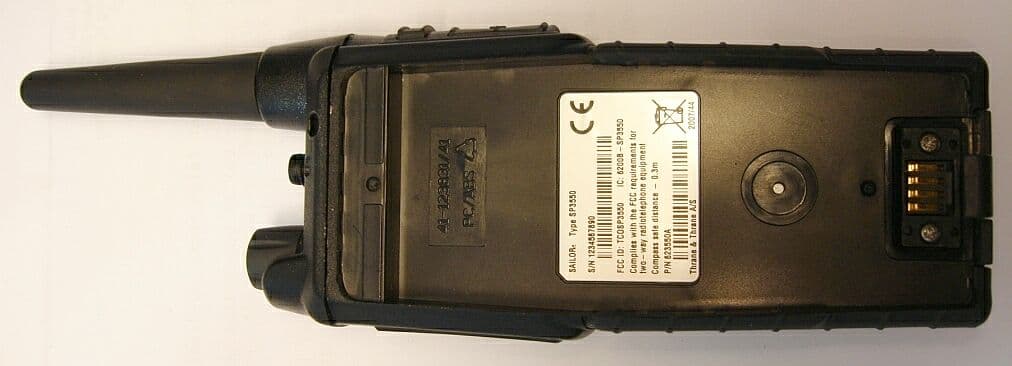
TCOSP3550
Jan 21, 2008UHF Transceiver
Equipment Class
TNF - Licensed Non-Broadcast Transmitter Held to Face
TCOSP3510
Jun 18, 2007Sailor SP3510 Hand Held VHF Radiotelephone
Equipment Class
TNF - Licensed Non-Broadcast Transmitter Held to Face
TCOSP3515
Jun 18, 2007Sailor SP3515 Hand Held VHF Radiotelephone
Equipment Class
TNF - Licensed Non-Broadcast Transmitter Held to Face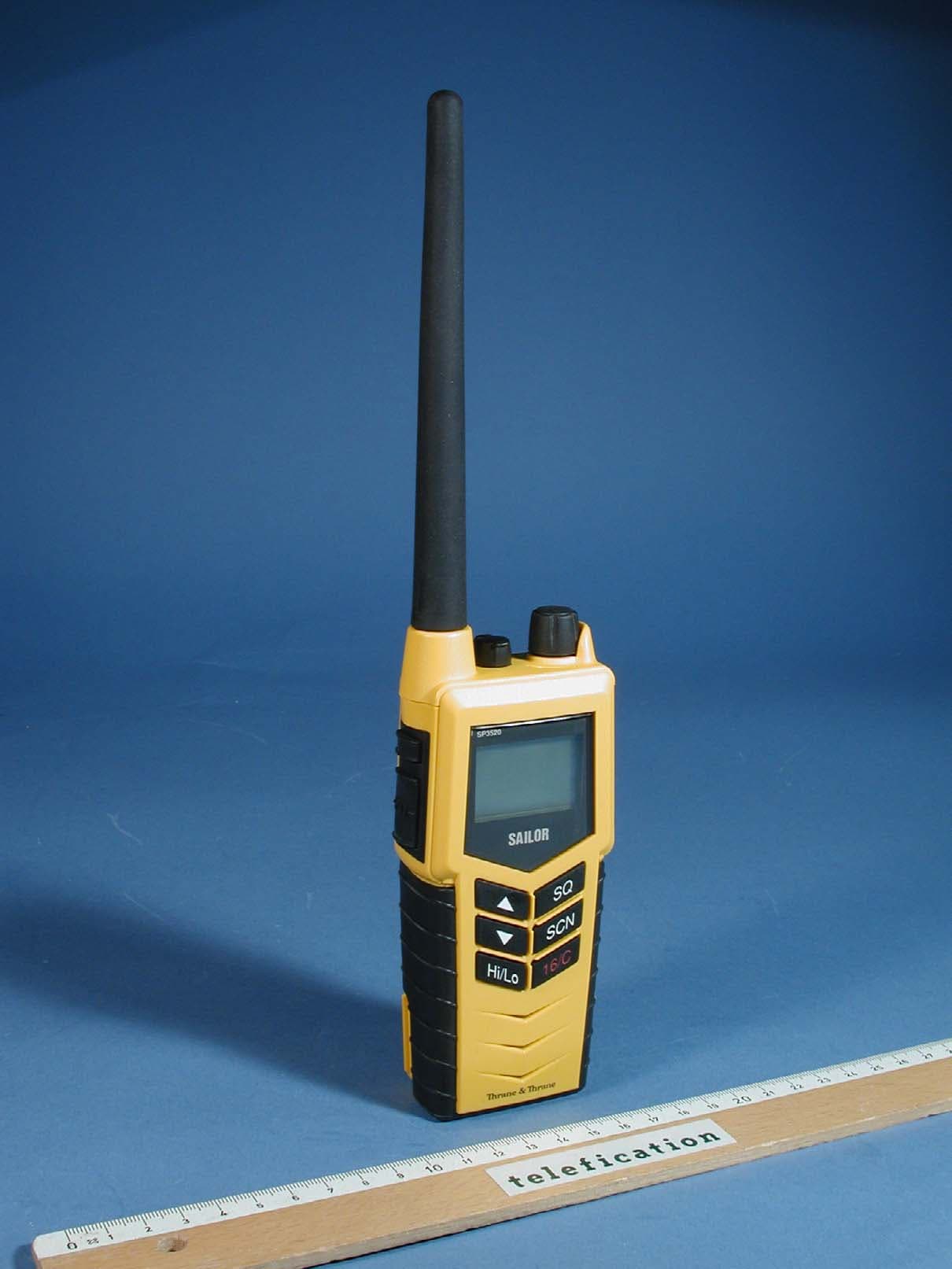
TCOSP3520
May 22, 2007Sailor SP3520 Hand Held VHF Radiotelephone (GMDSS)
Equipment Class
GHH - Part 80 VHF Hand Held Transmitter (GMDSS)
TCORT5020
Dec 11, 2005VHF Marine Radiotelephone
Equipment Class
GVH - Part 80 VHF Transmitter (GMDSS)