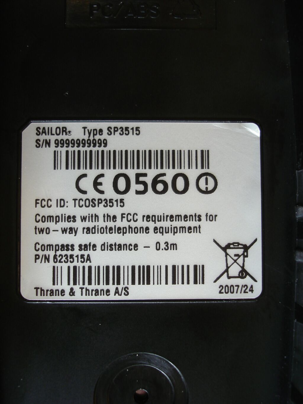
TCOSP3515Sailor SP3515 Hand Held VHF Radiotelephone
Thrane & Thrane A/S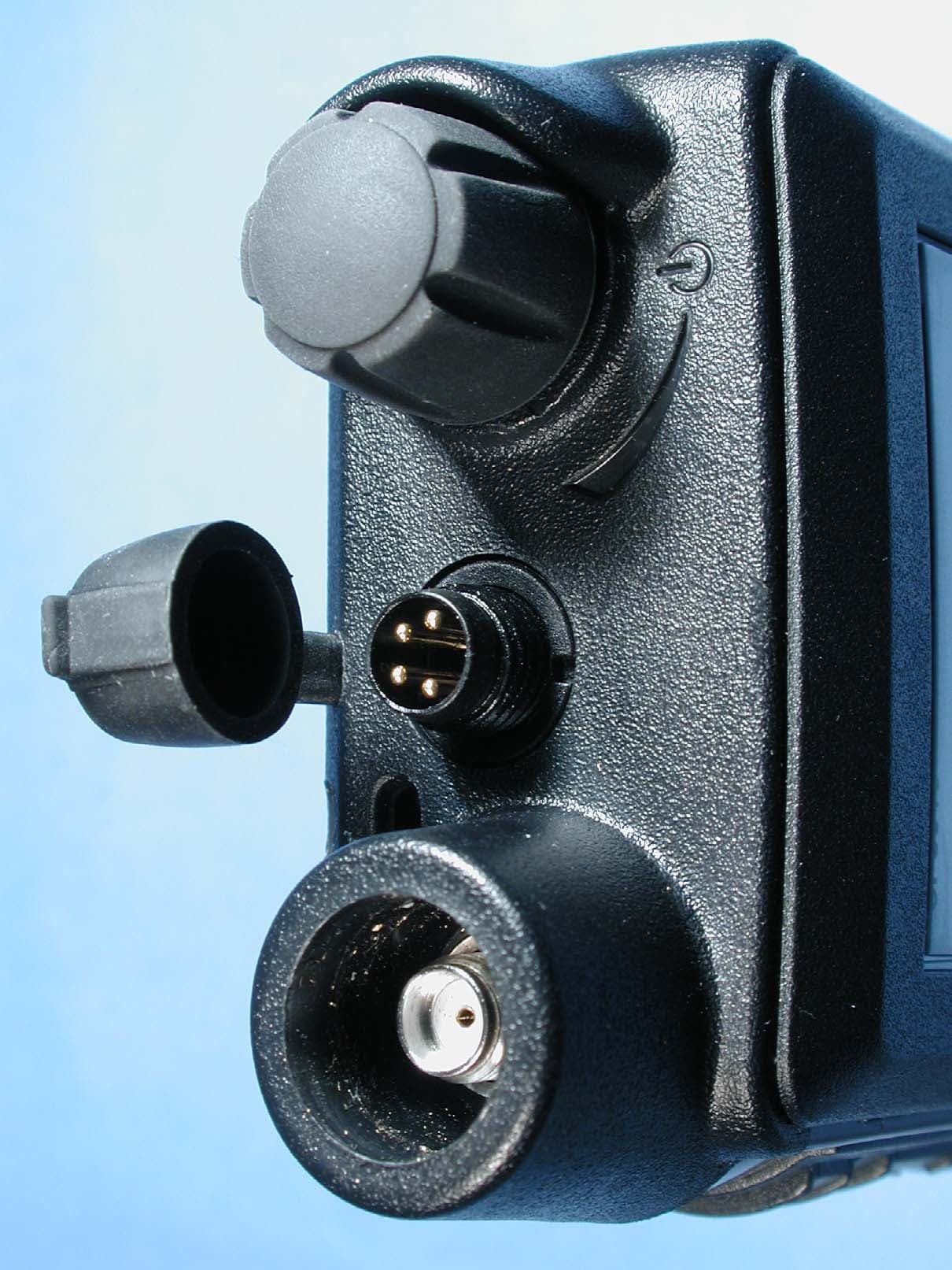
Click to zoom
Application Details
- Equipment Class
- TNF - Licensed Non-Broadcast Transmitter Held to Face
- Date of Grant
- Jun 18, 2007
- Application Purpose
- Original Equipment
- Date of Application
- Jun 18, 2007
- Equipment Note
- Sailor SP3515 Hand Held VHF Radiotelephone
- Frequency Range
- 155.00000000 - 163.42500000
- Company
- Thrane & Thrane A/S
- Country
- Denmark
Documents & Files
Document Text
Text extracted from the exhibit documents filed with the FCC. Open a document above to read the original.
Users Manual
SAILOR SP3515 VHF USER MANUAL Emergency procedure • Turn the knob at the top of the radio clockwise. The display lights up showing the last used channel and the battery level. • Select channel 16 (Distress or Safety), press the 16/C key. • Press the PTT and say: — “MAYDAY, MAYDAY, MAYDAY”, — “This is”..... ships name repeated three times — — “MAYDAY” — “This is”..... ships name and call sign, — The ship’s position in latitude and longitude or other reference to a known geographical location, — The nature of distress and assistance wanted, — Any other information which might facilitate the rescue. — “OVER” • Release PTT and listen for answer. 0709 i SP3515 VHF Document number: TT 98-124293-B Release date: March, 2007 Copyright: © 2007 Thrane & Thrane A/S. All rights reserved. Trademark Acknowledgements •SAILOR is a registered trademark of Thrane & Thrane A/S. •Other product and company names mentioned in this manual may be trademarks or trade names of their respective owners. Warranty limitation IMPORTANT - The radio is a sealed waterproof unit. To create and maintain its waterproof integrity it was assembled in a controlled environment using special equipment. The radio is not a user maintainable unit, and under no circumstances should the unit be opened except by authorized personnel. Unauthorized opening of the unit will invalidate the warranty. Disclaimer Any responsibility or liability for loss or damage in connection with the use of this product and the accompanying documentation is disclaimed by Thrane & Thrane. The information in this manual is provided for information purposes only, is subject to change without notice, may contain errors or inaccuracies, and represents no commitment whatsoever by Thrane & Thrane. This agreement is governed by the laws of Denmark. Manuals issued by Thrane & Thrane are periodically revised and updated. Anyone relying on this information should satisfy himself/herself as to the most current version. Providers with access to Thrane & Thrane's Extranet may obtain current copies of manuals at: http://extranet.thrane.com. Thrane & Thrane is not responsible for the content or accuracy of any translations or reproductions, in whole or in part, of this manual from any other source. 0709 ii Precautions Avoid water and salt in the I/O connector and keep it clean frequently. Only use original Thrane & Thrane battery packs. Make sure they are clean and dry before attaching the transceiver. Be careful not to damage any gaskets. Only use the original Thrane & Thrane charger for the rechargeable battery. Be very careful when handling the Lithium batteries. With correct use they are safe but any misuse might cause dangerous situations. Never short circuit the battery terminals, never expose the transceiver and the batteries to extreme temperature or fire and never use any kind of violence. Avoid close contact between the antenna and parts of the human body. The top of the antenna must never be closer than 5 cm to the body when transmitting. Do not submerge the transceiver more than 1 m for 30 minutes. Keep the transceiver at least 0.3 m away from the magnetic compass. 0709 iii Training information SAILOR SP3515 VHF is designed for "occupational use only". It must be operated by licensed personnel only. The SP3515 complies with the FCC RF exposure limits for "Occupational Use Only". • FCC OET Bulletin 65 Supplement C, evaluating compliance with FCC guidelines for human exposure to radio frequency electromagnetic fields. • American National Standards Institute (C95.1) IEEE standard for safety levels with respect to human exposure to radio frequency electromagnetic fields, 3 kHz to 300 GHz. • American National Standards Institute (C95.3) IEEE recommended practice for the measurement of potentially hazardous electromagnetic fields - RF and microwaves. Correct use For best performance, hold the radio vertically and 10 cm away from the head when talking into the microphone. Warning!Your Thrane & Thrane VHF radio generates electromagnetic RF (radio frequency) energy when transmitting. To ensure that you are not exposed to excessive amounts of energy and thus to avoid health hazards from excessive exposure to RF energy, all persons must be at least 5 cm away from the antenna when the radio is transmitting. 0703 iv 0641 v Contents Chapter 1 Introduction Your VHF .............................................................................1 Performance ....................................................................... 2 Channels ............................................................................ 2 Chapter 2 Operation Controls ..............................................................................5 Keys and buttons ................................................................5 The display ......................................................................... 7 Using the VHF .....................................................................8 Basic functions ...................................................................8 Other functions .................................................................. 11 Chapter 3 Batteries Battery level indication ......................................................15 Removing and inserting the battery pack ...........................15 The battery charger ...........................................................16 Installing the charger ........................................................16 Recharging the battery ......................................................17 Chapter 4 Configuring the radio Configuration mode ...........................................................19 Entering and using configuration mode ............................19 List of configuration settings ............................................. 20 0703 vi Chapter 5 Equipment and accessories External equipment .......................................................... 27 List of equipment ................................…
Text truncated - open the document above for the full version.
External Photos
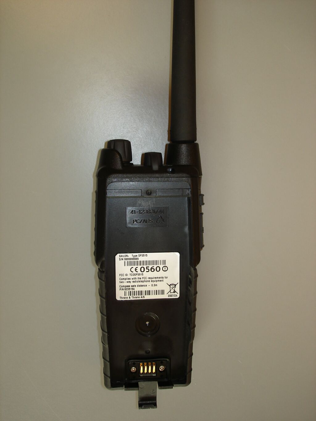
Photographs module 99822232 External PHOTOGRAPH 1: FRONT VIEW......................................................................................................................... 2 PHOTOGRAPH 2: REAR VIEW........................................................................................................................... 3 PHOTOGRAPH 3: TOP VIEW.............................................................................................................................. 4 PHOTOGRAPH 4: CHARGER............................................................................................................................. 5 Page: 2 of 5 Report number: 99822232 Photograph 1: Front view Page: 3 of 5 Report number: 99822232 Photograph 2: Rear view Page: 4 of 5 Report number: 99822232 Photograph 3: Top view Page: 5 of 5 Report number: 99822232 Photograph 4: Charger
Internal Photos
Photographs module 99822232 Internal PHOTOGRAPH 1: EXPLODED VIEW................................................................................................................... 2 PHOTOGRAPH 2: PCB TOP VIEW...................................................................................................................... 3 PHOTOGRAPH 3: PCB BOTTOM VIEW (UNCOVERED) ....................................................................................... 4 Page: 2 of 4 Report number: 99822232 Photograph 1: Exploded view Page: 3 of 4 Report number: 99822232 Photograph 2: PCB top view Page: 4 of 4 Report number: 99822232 Photograph 3: PCB bottom view (uncovered)
Test Report
Test report 99822232 based on: FCC Part 80 (10-1-06 Edition) VHF handheld radiotelephone SAILOR SP3515 Report number: 99822232 Contents MAIN MODULE.......................................................................................................................................................3 1 I NTRODUCTION ...............................................................................................................................................3 2 P RODUCT ........................................................................................................................................................4 3 T EST SCHEDULE ..............................................................................................................................................4 4 P RODUCT DOCUMENTATION ............................................................................................................................5 5 O BSERVATIONS AND COMMENTS .....................................................................................................................5 6 S UMMARY .......................................................................................................................................................5 7 C ONCLUSIONS .................................................................................................................................................6 TEST RESULTS MODULE.....................................................................................................................................7 1 S UMMARY .......................................................................................................................................................7 2 T EST RESULTS .................................................................................................................................................8 2.1 Radiated spurious (< 30 MHz), exploratory .........................................................................................8 2.2 Radiated spurious (> 30 MHz), cabinet radiation ................................................................................9 2.3 Conducted spurious at the antenna terminal.......................................................................................13 2.4 Occupied bandwidth ............................................................................................................................14 2.5 Frequency deviation ............................................................................................................................15 2.6 Modulation limitation ..........................................................................................................................16 2.7 Transmitter power ...............................................................................................................................17 2.8 Frequency stability..............................................................................................................................18 2.9 Human exposure to RF radiation ........................................................................................................19 USED TEST EQUIPMENT MODULE.................................................................................................................20 This report comprises of three modules. The total number of pages is: 20 Page: 3 of 20 Main module Report number: 99822232 Main module 1 Introduction This report contains the result of tests performed by: Telefication B.V. Edisonstraat 12a 6902 PK Zevenaar The Netherlands Telefication complies with the accreditation criteria for test laboratories as laid down in ISO/IEC 17025:2005. The accreditation covers the quality system of the laboratory as well as the specific activities as described in the authorized annex bearing the accreditation number L021 and is granted on 30 November 1990 by the Dutch Council For Accreditation (RvA: Raad voor Accreditatie). The copyright of this test report is owned by Telefication bv and may not be reproduced except in full without the written approval of Telefication bv. Ordering party: Company name : Thrane & Thrane A/S Address : Porsvej 2 Zipcode : 9000 City/town : Aalborg Country : Denmark Date of order : 30 November 2006 Page: 4 of 20 Main module Report number: 99822232 2 Product A sample of the following product was submitted for testing: Product name : VHF handheld radiotelephone Product category : Portable ship station (non GMDSS) Manufacturer : Thrane & Thrane A/S Trade mark : SAILOR Type designation : SP3515 FCC ID : TCOSP3515 Hardware version : -- Software version : 1.00.03 Serial number : 0148480009 3 Test schedule Tests are carried out in accordance with the specification detailed in chapter 6 "Summary" of this report. Tests are carried out at the following locations: • Telefication, Zevenaar; • TNO EPS, Niekerk (FCC listed site nr. 90828) Tests are carried out between: • 2 February and 16 March 2007 Page: 5 of 20 Main module Report number: 99822232 4 Product documentation For production of this report the following product documentation is used: Description Date Identification User manual SP3515 VHF 3/2007 TT-98-124293-A Issue:A/0703 The above mentioned documentation will be filed at Telefication B.V. Zevenaar for a period of 10 years following the issue of this report. 5 Observations and comments The SP 3515 VHF radio operates in the maritime frequency band from 155.000 to 163.425 MHz and in the land mobile band from 148.000 to 174.000 MHz. The channel spacing can be set to 25 kHz and 12,5 kHz. The radio can be set to use CTCSS and scrambling. These features are not used during the tests and only the 25 kHz the channel spacing is used during testing. The measurements are carried out, where relevant, with the sample in the highest power mode (5W). The measurements are carried out on channel 16 only, unless otherwise stated. 6 Summary The product is intended for use in …
Text truncated - open the document above for the full version.
Test Setup Photos
Photographs module 99822232 Test setup PHOTOGRAPH 1: TEST SETUP RADIATED EMISSIONS (<30 MHZ) ..................................................................... 2 PHOTOGRAPH 2: TEST SETUP RADIATED EMISSIONS (>30 MHZ) ..................................................................... 3 PHOTOGRAPH 3: TEST SETUP RADIATED EMISSIONS (>1 GHZ)........................................................................ 4 Page: 2 of 4 Report number: 99822232 Photograph 1: Test setup radiated emissions (<30 MHz) Page: 3 of 4 Report number: 99822232 Photograph 2: Test setup radiated emissions (>30 MHz) Page: 4 of 4 Report number: 99822232 Photograph 3: Test setup radiated emissions (>1 GHz)
Contact Information
Applicant
Helge Hoff(Senior Engineer)
Test Firm
Kiwa Nederland B.V.Willem Jong
[email protected]+31 889983621
Technical Specifications
| # | Rule Parts | Frequency Range | Power Output | Emission | Tolerance |
|---|---|---|---|---|---|
| 4 | 8 | 155 MHz - 163.425 MHz | 850.00 mW | 8K00G3E | 3 ppm |
Other Applications from Thrane & Thrane A/S
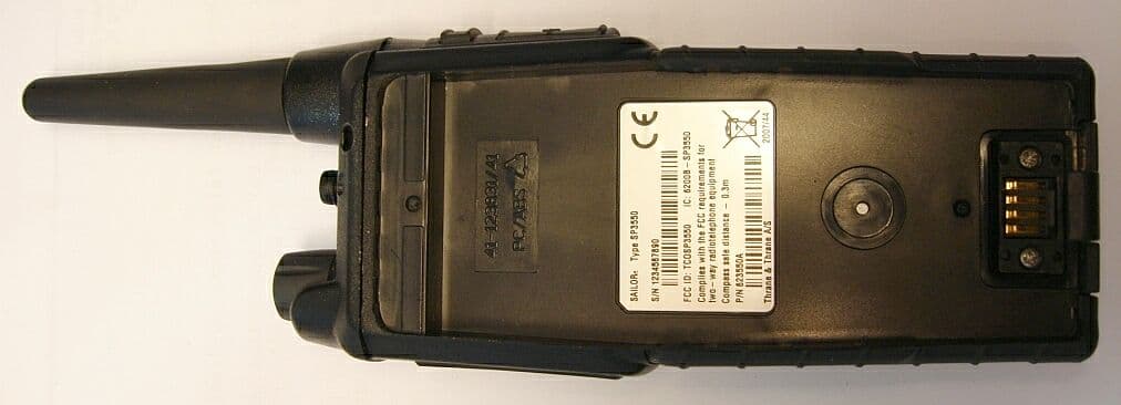
TCOSP3550
Jan 21, 2008UHF Transceiver
Equipment Class
TNF - Licensed Non-Broadcast Transmitter Held to Face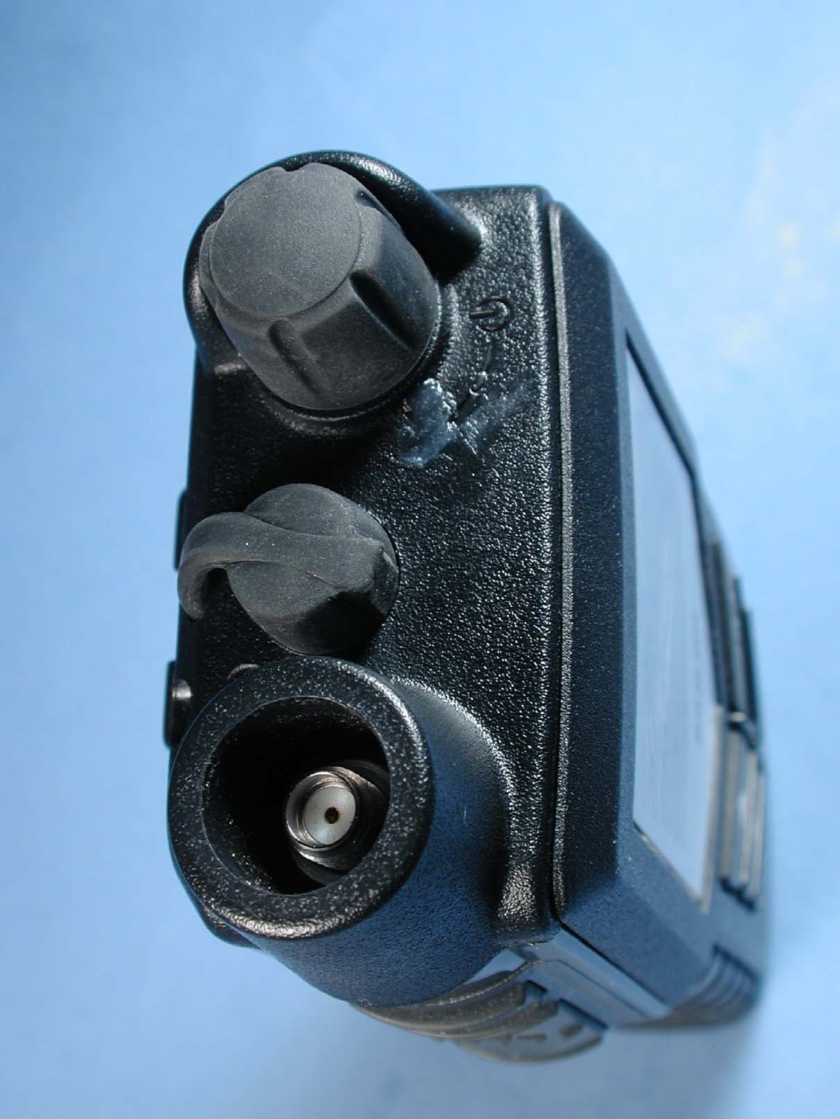
TCOSP3510
Jun 18, 2007Sailor SP3510 Hand Held VHF Radiotelephone
Equipment Class
TNF - Licensed Non-Broadcast Transmitter Held to Face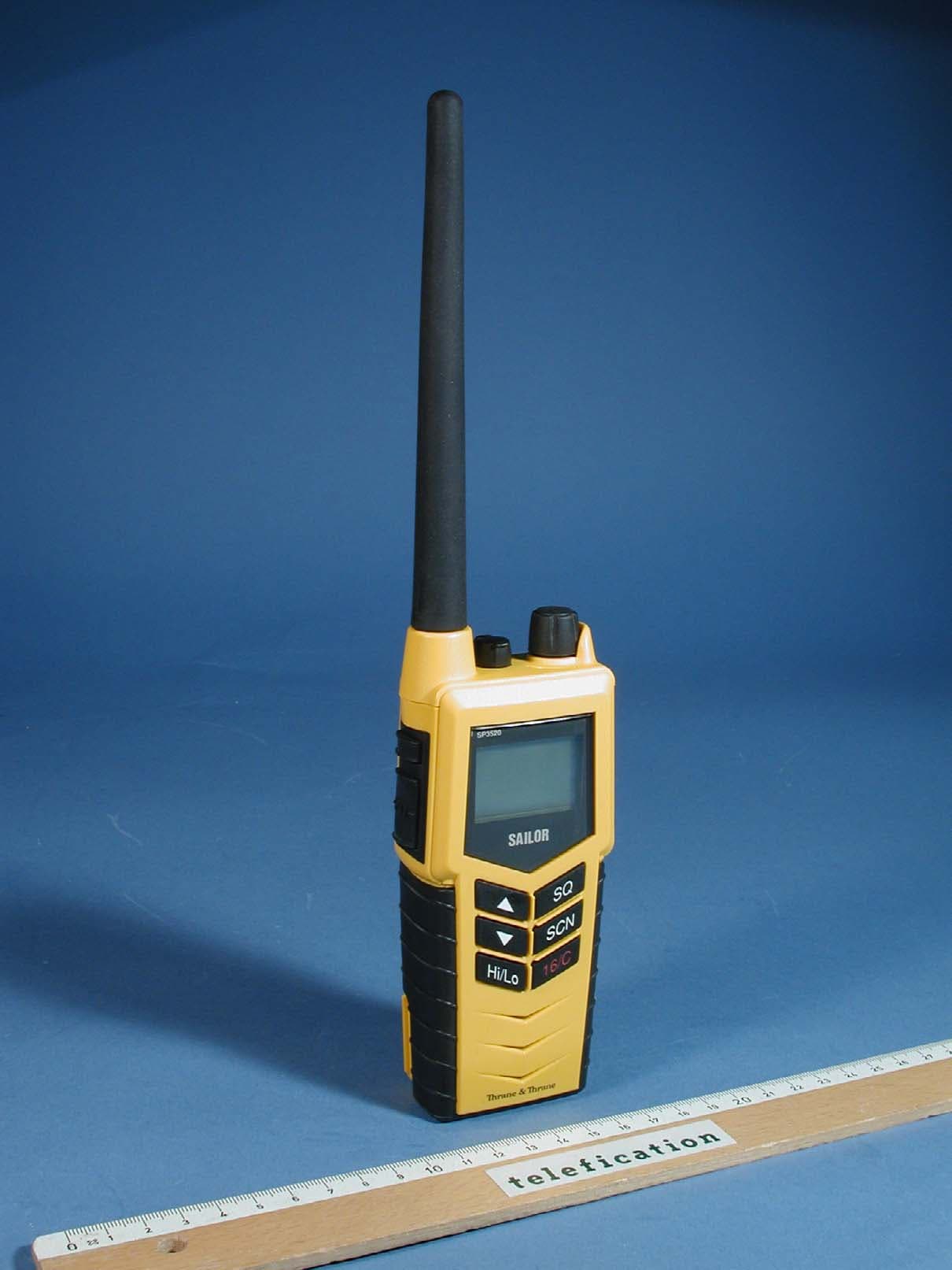
TCOSP3520
May 22, 2007Sailor SP3520 Hand Held VHF Radiotelephone (GMDSS)
Equipment Class
GHH - Part 80 VHF Hand Held Transmitter (GMDSS)
TCORT5020
Dec 11, 2005VHF Marine Radiotelephone
Equipment Class
GVH - Part 80 VHF Transmitter (GMDSS)
TCORT5022
Jun 28, 2005VHF Marine Radiotelephone
Equipment Class
GVH - Part 80 VHF Transmitter (GMDSS)