TE7D2V1A750 Wireless Dual Band Gigabit ADSL2+ Modem Router
TP-Link Technologies Co., Ltd.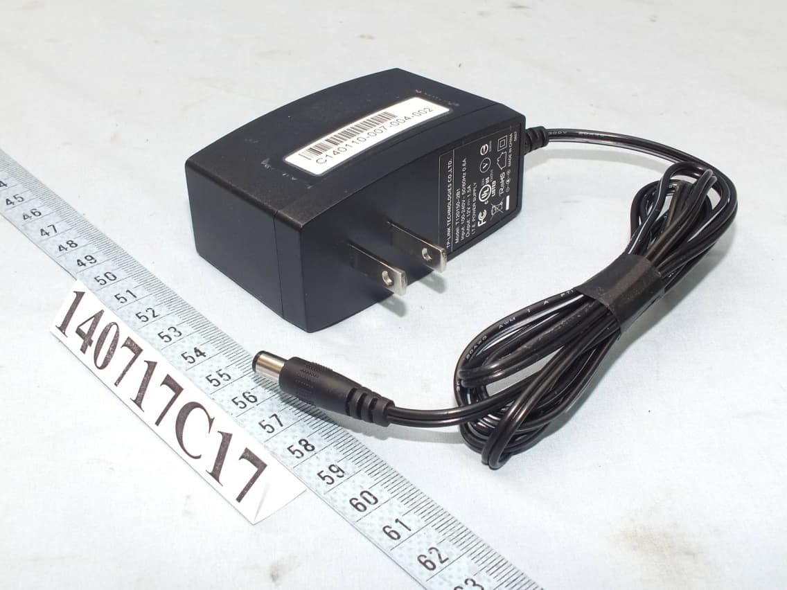
Click to zoom
Application Details
- Equipment Class
- DTS - Digital Transmission System
- Date of Grant
- Oct 28, 2014
- Application Purpose
- Original Equipment
- Date of Application
- Oct 14, 2014
- Equipment Note
- A750 Wireless Dual Band Gigabit ADSL2+ Modem Router
- Frequency Range
- 2412.00000000 - 2462.00000000
- Country
- China
Documents & Files
Document Text
Text extracted from the exhibit documents filed with the FCC. Open a document above to read the original.
Users Manual
Archer D2 AC750 Wireless Dual Band Gigabit ADSL2+ Modem Router Rev: 1.0.0 1910011088 COPYRIGHT & TRADEMARKS Specifications are subject to change without notice. is a registered trademark of TP-LINK TECHNOLOGIES CO., LTD. Other brands and product names are trademarks or registered trademarks of their respective holders. No part of the specifications may be reproduced in any form or by any means or used to make any derivative such as translation, transformation, or adaptation without permission from TP-LINK TECHNOLOGIES CO., LTD. Copyright © 2014 TP-LINK TECHNOLOGIES CO., LTD. All rights reserved. http://www.tp-link.com FCC STATEMENT This equipment has been tested and found to comply with the limits for a Class B digital device, pursuant to part 15 of the FCC Rules. These limits are designed to provide reasonable protection against harmful interference in a residential installation. This equipment generates, uses and can radiate radio frequency energy and, if not installed and used in accordance with the instructions, may cause harmful interference to radio communications. However, there is no guarantee that interference will not occur in a particular installation. If this equipment does cause harmful interference to radio or television reception, which can be determined by turning the equipment off and on, the user is encouraged to try to correct the interference by one or more of the following measures: • Reorient or relocate the receiving antenna. • Increase the separation between the equipment and receiver. • Connect the equipment into an outlet on a circuit different from that to which the receiver is connected. • Consult the dealer or an experienced radio/ TV technician for help. This device complies with part 15 of the FCC Rules. Operation is subject to the following two conditions: 1) This device may not cause harmful interference. 2) This device must accept any interference received, including interference that may cause undesired operation. Any changes or modifications not expressly approved by the party responsible for compliance could void the user’s authority to operate the equipment. Note: The manufacturer is not responsible for any radio or TV interference caused by unauthorized modifications to this equipment. Such modifications could void the user’s authority to operate the equipment. FCC RF Radiation Exposure Statement This equipment complies with FCC RF radiation exposure limits set forth for an uncontrolled environment. This device and its antenna must not be co-located or operating in conjunction with any other antenna or transmitter. “To comply with FCC RF exposure compliance requirements, this grant is applicable to only Mobile Configurations. The antennas used for this transmitter must be installed to provide a separation distance of at least 20 cm from all persons and must not be co-located or operating in conjunction with any other antenna or transmitter.” CE Mark Warning This is a class B product. In a domestic environment, this product may cause radio interference, in which case the user may be required to take adequate measures. National Restrictions This device is intended for home and office use in all EU countries (and other countries following the EU directive 1999/5/EC) without any limitation except for the countries mentioned below: Country Restriction Reason/remark Bulgaria None General authorization required for outdoor use and public service France Outdoor use limited to 10 mW e.i.r.p. within the band 2454-2483.5 MHz Military Radiolocation use. Refarming of the 2.4 GHz band has been ongoing in recent years to allow current relaxed regulation. Full implementation planned 2012 Italy None If used outside of own premises, general authorization is required Luxembourg None General authorization required for network and service supply(not for spectrum) Norway Implemented This subsection does not apply for the geographical area within a radius of 20 km from the centre of Ny-Ålesund Russian Federation None Only for indoor applications Note: Please don’t use the product outdoors in France. Canadian Compliance Statement This device complies with Industry Canada license-exempt RSS standard(s). Operation is subject to the following two conditions: (1)This device may not cause interference, and (2)This device must accept any interference, including interference that may cause undesired operation of the device. Cet appareil est conforme aux norms CNR exemptes de licence d’Industrie Canada. Le fonctionnement est soumis aux deux conditions suivantes: (1)cet appareil ne doit pas provoquer d’interférences et (2)cet appareil doit accepter toute interférence, y compris celles susceptibles de provoquer un fonctionnement non souhaité de l’appareil. This device has been designed to operate with the antennas listed below, and having a maximum gain of 5 dBi. Antennas not included in this list or having a gain greater than 5 dBi are strictly prohibited for use with this device. The required antenna impedance is 50 ohms. To reduce potential radio interference to other users, the antenna type and its gain should be so chosen that the equivalent isotropically radiated power (e.i.r.p.) is not more than that permitted for successful communication. Industry Canada Statement Complies with the Canadian ICES-003 Class B specifications. Cet appareil numérique de la classe B est conforme à la norme NMB-003 du Canada. This device complies with RSS 210 of Industry Canada. This Class B device meets all the requirements of the Canadian interference-causing equipment regulations. Cet appareil numérique de la Classe B respecte toutes les exigences du Règlement sur le matériel brouilleur du Canada. Korea Warning Statements: 당해 무선설비는 운용중 전파혼신 가능성이 있음. NCC Notice& BSMI Notice: 注意! 依據 低功率電波輻射性電機管理辦法 第十二條 經型式認證合格之低功率射頻電機,非經許可,公司、商號或使用者均不得擅自變更頻率、 加大功率或變更原設計之特性或功能。 第十四條 低功率射頻電機之使用不得影響飛航安全及干擾合法通行;經發現有干擾現象時,應立即 停用,並改善至無干擾時方得繼續使用。前項合法通信,指依電信規定作業之無線電信。低功率射 頻電機需忍受合法通信或工業、科學以及醫療用電波輻射性電機設備之干擾。 減少電磁波影響,請妥適使用。 …
Text truncated - open the document above for the full version.
Attestation Statements
TP-Link Technologies Co., Ltd. Building 24 (floors 1,3,4,5) and 28 (floors1-4), Central Science and Technology Park, Nanshan, Shenzhen, China Declaration for no non‐US channel operation August 28, 2014 We, TP-LINK TECHNOLOGIES CO., LTD declare that the device does not support channel 12 ~ 13 in 2.4GHz band and any non-US channels in all the operational mode(s) for the following product. FCC ID:TE7D2V1 If you should have any question(s) regarding this declaration, please don’t hesitate to contact us. Thank you! Name of authorized signer: Yongquan Wang Title of authorized signer: Product Dept. Manager Company Name: TP‐LINK Technologies Co., Ltd. Tel: 86‐755‐26525554 Fax: 86‐755‐26508930 Web site: WWW.TP‐LINK.COM E‐mail: public@tp‐link.com.cn
Attestation Statements
TP-Link Technologies Co., Ltd. Building 24 (floors 1,3,4,5) and 28 (floors1-4), Central Science and Technology Park, Nanshan, Shenzhen, China Attestation for FCC Declaration of Conformity FCC ID: TE7D2V1Date: 2014-09-01 Please be notified that we, the undersigned, TP-LINK TECHNOLOGIES CO., LTD declare that the product bears the above FCC ID is also complying with the requirements of FCC DoC. The test report number for FCC DoC is FD140717C17, with is issued by an accredited lab, Bureau Veritas Consumer Products Services (H.K.) Ltd., Taoyuan Branch (BV CPS Taoyuan) of Taiwan. Which has been accredited in accordance to all of the requirements of 47CFR 2.948(d) and (e) of the FCC rules and KDB349827. Sincerely, Name of authorized signer: Yongquan Wang Title of authorized signer: Product Dept. Manager Company Name: TP‐LINK Technologies Co., Ltd. Tel:86‐755‐26525554 Fax:86‐755‐26508930 Web site: WWW.TP‐LINK.COM E‐mail:public@tp‐link.com.cn
Cover Letter(s)
TP-Link Technologies Co., Ltd. Building 24 (floors 1,3,4,5) and 28 (floors1-4), Central Science and Technology Park, Nanshan, Shenzhen, China Date: 2014‐08‐28 FCC ID: TE7D2V1 To the attention of Federal Communications Commission Authorization and Evaluation Division Confidentiality Request Pursuant to Sections 0.457 and 0.459 of the Commission’s Rules, the Applicant hereby requests confidential treatment of information accompanying this Application as outlined below: Schematics Block Diagram Operational Description The above materials contain trade secrets and proprietary information not customarily released to the public. The public disclosure of these matters might be harmful to the Applicant and provide unjustified benefits to its competitors. The Applicant understands that pursuant to Rule 0.457, disclosure of this Application and all accompanying documentation will not be made before the date of the Grant for this application. Sincerely yours, Name: Yongquan Wang TP‐Link Technologies Co., Ltd. Tel.: +86‐755‐26502509 Fax.: +86‐755‐26508930 E‐mail: public@tp‐link.com.cn
Cover Letter(s)
TP-Link Technologies Co., Ltd. Building 24 (floors 1,3,4,5) and 28 (floors1-4), Central Science and Technology Park, Nanshan, Shenzhen, China Date: 2014‐08‐28 AUTHORIZATION LETTER To whom it may concern: We, the undersignedTP‐Link Technologies Co., Ltd., hereby authorize Bureau Veritas Consumer Products Services (H.K.) Ltd., Taoyuan Branch (BV CPS Taoyuan) of Taiwan to act on our behalf in all matters relating to all processes required in FCC approval and any communication needed with the national authority. Any and allacts carried out by BV CPS Taoyuan on our behalf shall have the same effects as acts of our own. If you have any questions regarding the authorization, please don’t hesitate to contact us. Thank you! Sincerely yours, Name: Yongquan Wang TP‐Link Technologies Co., Ltd. Tel.: +86‐755‐26502509 Fax.: +86‐755‐26508930 E‐mail: public@tp‐link.com.cn
External Photos
Page 1 CONSTRUCTION PHOTOS OF EUT Page 2 Page 3 Page 4
ID Label/Location Info
Label Location
ID Label/Location Info
C B A 12 C 345678 B E D D A 9 料号: 12345 E 6789 与上一版的区别 颜 色 名 称 版 本 材 质 模 具 机型版本号 logo 底色 文字 其它 结构工程师 硬件工程师 产品工程师 平面负责人 记 录 审 核 完成日期 设 计 Archer D2(UN)_1.0_产品规格标贴 A1 75#PET+普通雾膜 壳体尾桨-229 Archer D2(UN)_1.0 徐宾徽 2014-5-13 Pantone 432 C 详见标注 19.5 181.63 187.54 4-R0.5 3-5mm 3mm 3-5mm 文字方向 文字方向 文字方向 走纸示意图: 跳距:3mm 边距:3~5mm AC750 Wireless Dual Band Gigabit ADSL2+ Modem Router Model: Default Access: This device complies with part 15 of the FCC Rules. Operation is subject to the following two conditions:(1) This device may not cause harmful interference, and (2) this device must accept any interference received, including interference that may cause undesired operation. IC:8853A-D2 FCC ID:TE7D2V1 Wireless Password /PIN Serial Number MAC Address SSID
Internal Photos
Page 5 Page 6 Page 7 Page 8 2.4 & 5GHz Antenna 2.4GHz Antenna Page 9 Page 10
RF Exposure Info
Report No.: SA140717C17 1 of 6 Report Format Version 5.0.0 RF EXPOSURE REPORT REPORT NO.: SA140717C17 MODEL NO.: Archer D2 FCC ID: TE7D2V1 RECEIVED: Jul. 17, 2014 TESTED: Aug. 10 ~ Sep. 30, 2014 ISSUED: Sep. 30, 2014 APPLICANT: TP-LINK TECHNOLOGIES CO., LTD. ADDRESS: Building 24 (floors 1,3,4,5) and 28 (floors1-4) Central Science and Technology Park, Shennan Rd, Nanshan, Shenzhen, China ISSUED BY: Bureau Veritas Consumer Products Services (H.K.) Ltd., Taoyuan Branch LAB ADDRESS: No. 47-2, 14th Ling, Chia Pau Vil., Lin Kou Dist., New Taipei City, Taiwan, R.O.C. TEST LOCATION: No. 19, Hwa Ya 2nd Rd, Wen Hwa Tsuen, Kwei Shan Hsiang, Taoyuan Hsien 333, Taiwan, R.O.C. This report is for your exclusive use. Any copying or replication of this report to or for any other person or entity, or use of our name or trademark, is permitted only with our prior written permission. This report sets forth our findings solely with respect to the test samples identified herein. The results set forth in this report are not indicative or representative of the quality or characteristics of the lot from which a test sample was taken or any similar or identical product unless specifically and expressly noted. Our report includes all of the tests requested by you and the results thereof based upon the information that you provided to us. You have 60 days from date of issuance of this report to notify us of any material error or omission caused by our negligence, provided, however, that such notice shall be in writing and shall specifically address the issue you wish to raise. A failure to raise such issue within the prescribed time shall constitute your unqualified acceptance of the completeness of this report, the tests conducted and the correctness of the report contents. Unless specific mention, the uncertainty of measurement has been explicitly taken into account to declare the compliance or non-com pliance to the specification. Report No.: SA140717C17 2 of 6 Report Format Version 5.0.0 TABLE OF CONTENTS RELEASE CONTROL RECORD .............................................................................................. 3 1. CERTIFICATION ...................................................................................................... 4 2. RF EXPOSURE ....................................................................................................... 5 2.1 LIMITS FOR MAXIMUM PERMISSIBLE EXPOSURE (MPE) ................................. 5 2.2 MPE CALCULATION FORMULA ............................................................................. 5 2.3 CLASSIFICATION .................................................................................................... 5 2.4 CALCULATION RESULT OF MAXIMUM CONDUCTED POWER .......................... 6 Report No.: SA140717C17 3 of 6 Report Format Version 5.0.0 RELEASE CONTROL RECORD ISSUE NO. REASON FOR CHANGE DATE ISSUED SA140717C17 Original release Sep. 30, 2014 Report No.: SA140717C17 4 of 6 Report Format Version 5.0.0 1. CERTIFICATION PRODUCT: AC750 Wireless Dual Band Gigabit ADSL2+ Modem Router MODEL NO.: Archer D2 BRAND: TP-LINK APPLICANT: TP-LINK TECHNOLOGIES CO., LTD. TESTED: Aug. 10 ~ Sep. 30, 2014 TEST SAMPLE: PROTOTYPE STANDARDS: FCC Part 2 (Section 2.1091) KDB 447498 D03 IEEE C95.1 The above equipment (model: Archer D2) has been tested by Bureau Veritas Consumer Products Services (H.K.) Ltd., Taoyuan Branch, and found compliance with the requirement of the above standards. The test record, data evaluation & Equipment Under Test (EUT) configurations represented herein are true and accurate accounts of the measurements of the sample’s EMC characteristics under the conditions specified in this report. PREPARED BY :, DATE :Sep. 30, 2014 Celine Chou / Specialist APPROVED BY : , DATE :Sep. 30, 2014 Ken Liu / Senior Manager Report No.: SA140717C17 5 of 6 Report Format Version 5.0.0 2. RF EXPOSURE 2.1 LIMITS FOR MAXIMUM PERMISSIBLE EXPOSURE (MPE) FREQUENCY RANGE (MHz) ELECTRIC FIELD STRENGTH (V/m) MAGNETIC FIELD STRENGTH (A/m) POWER DENSITY (mW/cm 2 ) AVERAGE TIME (minutes) LIMITS FOR GENERAL POPULATION / UNCONTROLLED EXPOSURE 300-1500 ... ... F/1500 30 1500-100,000 ... ... 1.0 30 F = Frequency in MHz 2.2 MPE CALCULATION FORMULA Pd = (Pout*G) / (4*pi*r 2 ) where Pd = power density in mW/cm 2 Pout = output power to antenna in mW G = gain of antenna in linear scale Pi = 3.1416 R = distance between observation point and center of the radiator in cm 2.3 CLASSIFICATION The antenna of this product, under normal use condition, is at least 20cm away from the body of the user. So, this device is classified as Mobile Device. Report No.: SA140717C17 6 of 6 Report Format Version 5.0.0 2.4 CALCULATION RESULT OF MAXIMUM CONDUCTED POWER FREQUENCY BAND (MHz) MAX POWER (dBm) ANTENNA GAIN (dBi) DISTANCE (cm) POWER DENSITY (mW/cm 2 ) LIMIT (mW/cm 2 ) 2412-2462 19.70 6.77 20 0.088 1 5180-5240 18.06 3.00 20 0.025 1 5745-5825 16.18 3.00 20 0.016 1 NOTE: 2.4GHz: Directional gain = 2dBi + 10log(3) = 6.77dBi CONCLUSION: The formula of calculated the MPE is: CPD1 / LPD1 + CPD2 / LPD2 + ......etc. < 1 CPD = Calculation power density LPD = Limit of power density 2.4GHz + 5GHz = 0.088 + 0.025 = 0.113 Therefore the maximum calculations of above situations are less than the “1” limit.
Test Report
Report No.: RF140717C17 1 of 80 Report Format Version 5.2.1 FCC TEST REPORT (15.247) REPORT NO.: RF140717C17 MODEL NO.: Archer D2 FCC ID: TE7D2V1 RECEIVED: Jul. 17, 2014 TESTED: Aug. 10 ~ Sep. 30, 2014 ISSUED: Sep. 30, 2014 APPLICANT: TP-LINK TECHNOLOGIES CO., LTD. ADDRESS: Building 24 (floors 1,3,4,5) and 28 (floors1-4) Central Science and Technology Park, Shennan Rd, Nanshan, Shenzhen, China ISSUED BY: Bureau Veritas Consumer Products Services (H.K.) Ltd., Taoyuan Branch LAB ADDRESS: No. 47-2, 14th Ling, Chia Pau Vil., Lin Kou Dist., New Taipei City, Taiwan, R.O.C. TEST LOCATION: No. 19, Hwa Ya 2nd Rd, Wen Hwa Tsuen, Kwei Shan Hsiang, Taoyuan Hsien 333, Taiwan, R.O.C. This report is for your exclusive use. Any copying or replication of this report to or for any other person or entity, or use of our name or trademark, is permitted only with our prior written permission. This report sets forth our findings solely with respect to the test samples identified herein. The results set forth in this report are not indicative or representative of the quality or characteristics of the lot from which a test sample was taken or any similar or identical product unless specifically and expressly noted. Our report includes all of the tests requested by you and the results thereof based upon the information that you provided to us. You have 60 days from date of issuance of this report to notify us of any material error or omission caused by our negligence, provided, however, that such notice shall be in writing and shall specifically address the issue you wish to raise. A failure to raise such issue within the prescribed time shall constitute your unqualified acceptance of the completeness of this report, the tests conducted and the correctness of the report contents. Unless specific mention, the uncertainty of measurement has been explicitly taken into account to declare the compliance or non-com pliance to the specification. This report should not be used by the client to claim product certification, approval, or endorsement by TAF or any government agencies. Report No.: RF140717C17 2 of 80 Report Format Version 5.2.1 TABLE OF CONTENTS RELEASE CONTROL RECORD ................................................................................................................ 4 1. CERTIFICATION ............................................................................................................................ 5 2. SUMMARY OF TEST RESULTS ................................................................................................... 6 2.1 MEASUREMENT UNCERTAINTY ................................................................................................ 6 3. GENERAL INFORMATION ............................................................................................................ 7 3.1 GENERAL DESCRIPTION OF EUT .............................................................................................. 7 3.2 DESCRIPTION OF TEST MODES ................................................................................................ 8 3.2.1 TEST MODE APPLICABILITY AND TESTED CHANNEL DETAIL ................................................ 9 3.3 DUTY CYCLE OF TEST SIGNAL ................................................................................................ 11 3.4 DESCRIPTION OF SUPPORT UNITS ........................................................................................ 12 3.4.1 CONFIGURATION OF SYSTEM UNDER TEST ......................................................................... 12 3.5 GENERAL DESCRIPTION OF APPLIED STANDARDS ............................................................. 13 4. TEST TYPES AND RESULTS ..................................................................................................... 14 4.1 RADIATED EMISSION AND BANDEDGE MEASUREMENT ..................................................... 14 4.1.1 LIMITS OF RADIATED EMISSION AND BANDEDGE MEASUREMENT ................................... 14 4.1.2 TEST INSTRUMENTS ................................................................................................................. 15 4.1.3 TEST PROCEDURES ................................................................................................................. 16 4.1.4 DEVIATION FROM TEST STANDARD ....................................................................................... 16 4.1.5 TEST SETUP ............................................................................................................................... 17 4.1.6 EUT OPERATING CONDITIONS ................................................................................................ 18 4.1.7 TEST RESULTS .......................................................................................................................... 19 4.2 CONDUCTED EMISSION MEASUREMENT .............................................................................. 40 4.2.1 LIMITS OF CONDUCTED EMISSION MEASUREMENT ........................................................... 40 4.2.2 TEST INSTRUMENTS ................................................................................................................. 40 4.2.3 TEST PROCEDURES ................................................................................................................. 41 4.2.4 DEVIATION FROM TEST STANDARD ....................................................................................... 41 4.2.5 TEST SETUP ............................................................................................................................... 41 4.2.6 EUT OPERATING CONDITIONS ................................................................................................ 41 4.2.7 TEST RESULTS .......................................................................................................................... 42 4.3 6dB BANDWIDTH MEASUREMENT .......................................................................…
Text truncated - open the document above for the full version.
Test Setup Photos
1 PHOTOGRAPHS OF THE TEST CONFIGURATION CONDUCTED EMISSION TEST 2 RADIATED EMISSION TEST
Contact Information
Applicant
Jing Huang(Regulatory Compliance Manager)
Technical Contact
Test Firm
Bureau Veritas CPS (H.K.) Ltd., Taoyuan BranchRichard Chen
Technical Specifications
| # | Rule Parts | Frequency Range | Power Output |
|---|---|---|---|
| 1 | 15C | 2.41 GHz - 2.46 GHz | 93.00 mW |
Other Applications from TP-Link Technologies Co., Ltd.
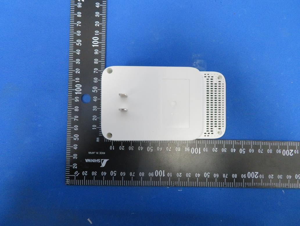
TE7RE230V2
Jan 13, 2021AC750 Wi-Fi Range Extender, AC1200 Wi-Fi Range Extender
Equipment Class
DTS - Digital Transmission System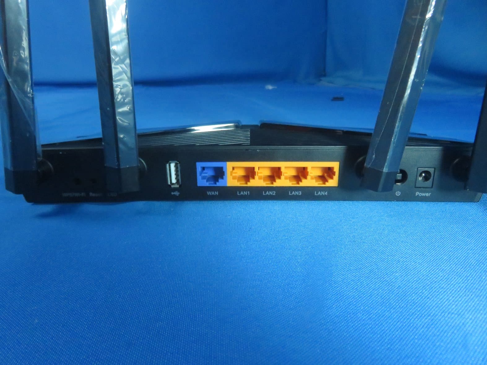
TE7AX20V2
Dec 22, 2020AX1800 Dual-Band Wi-Fi 6 Router
Equipment Class
DTS - Digital Transmission System
TE7EAP620HD
Dec 17, 2020AX1800 Wireless Dual-Band Gigabit Ceiling Mount Access Point
Equipment Class
NII - Unlicensed National Information Infrastructure TX
TE7KP303V2
Dec 15, 2020Kasa Smart Wi-Fi Power Strip, 3-Outlet
Equipment Class
DTS - Digital Transmission System
TE7RE550
Dec 03, 2020AC1750 Wi-Fi Range Extender, AC1900 MU-MIMO Wi-Fi Range Extender
Equipment Class
DTS - Digital Transmission System