TE7EAP220N600 Wireless Dual Band Gigabit Access Point
TP-Link Technologies Co., Ltd.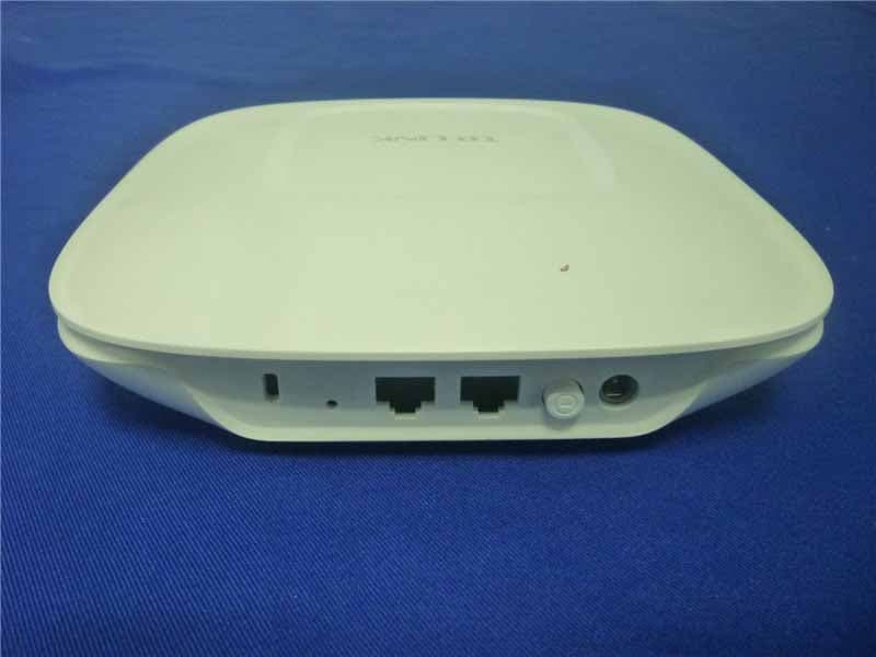
Click to zoom
Application Details
- Equipment Class
- DTS - Digital Transmission System
- Date of Grant
- Apr 18, 2015
- Application Purpose
- Original Equipment
- Date of Application
- Apr 15, 2015
- Equipment Note
- N600 Wireless Dual Band Gigabit Access Point
- Frequency Range
- 2412.00000000 - 2462.00000000
- Country
- China
Documents & Files
Document Text
Text extracted from the exhibit documents filed with the FCC. Open a document above to read the original.
Users Manual
Installation Guide Wireless N Gigabit Access Point EAP120 / EAP220 CONTENTS About This Installation Guide This guide is designed to familiarize you with the general layout of the EAP, describe how to deploy the device in your network and how to configure the device. Your EAP has more features and functionalities which can be found in the User Guide. Network Topology Requirements —————————————— 01 Overview ————————————————————————— 02 Hardware Installation ——————————————————— 04 1. Installation Requirements ....................................................... 04 2. Mounting Bracket ................................................................... 04 3. Installation ............................................................................ 05 4. Powering Mode ...................................................................... 09 Getting Started with the EAP ———————————————— 11 Q&A ——————————————————————————— 14 Specifications ——————————————————————— 15 Technical Support ————————————————————— 16 01 Network Topology Requirements Typical topology for the EAP is described below. Router Internet Switch Master EAPSlave EAPSlave EAP Enwuvgt Typical Topology The EAP120 and EAP220 provide two management modes: Cluster and Standalone. By default , the management mode is Cluster. In this mode, all the EAPs in the same LAN will form a Cluster, and a Master EAP will be elected among them to manage the other EAPs, called Slave EAPs. A DHCP server is required in the local network to assign IP addresses to the EAPs. A router usually acts as the DHCP server. Typically, a PoE switch can be used to provide Power over Ethernet for each EAP. Or, each EAP must be powered with a power adapter individually. 02 Overview ■ LED Explanation System LED Top View of the EAP LED StatusIndication Quickly flashing greenSystem initialization is complete. Solid greenThe device is working properly. Slowly flashing redThe system is abnormal. RAM, Flash, Ethernet, WLAN or firmware may be malfunctioning. Quickly flashing yellowFirmware is being updated. Alternating red/green/yellow twiceThe device is being reset. ■ Interface Panel RESET CONSOLEETHERNET ON/OFF POWER ARROW 1 Interface Panel of the EAP The interface panel components of the EAP, from left to right, are described in the following list: Kensington Security Slot Secure the lock into the slot to prevent the device from being stolen. 03 RESET With the device powered on, press and hold the RESET button for about 8 seconds, and then release the button. The device will restore to factory default settings. CONSOLE This port is used to connect with the serial port of a computer or a terminal to check and monitor simple system information of the device. ETHERNET This port is for connection to a router or switch to transmit and receive data as well as to a PSE device for power supply. Power sourcing equipment (PSE) is a device such as a switch that provides power over Ethernet cables to linked devices. ON/OFF Press this button to power on/off the device. Please remember to press it to use the device. POWER The power jack is for connection to the power adapter. Please use the power adapter provided. Refer to Powering Mode to learn how to power the device via PoE and power adapter. ARROW 1 To align with ARROW 2 in the mounting bracket before the EAP locks into place. Please refer to Mounting Bracket to locate ARROW 2. 04 Hardware Installation The EAP can be wall or ceiling mounted and can be powered via a PSE device or the provided adapter. Please suitably arrange your wire layout before the mounting. 1. Installation Requirements Check and prepare the following items in the package for installation. One EAP One Mounting Bracket One Installation Guide Three Nuts/ Washers/ Plastic Extending Tubes/ Self-tapping Screws/ Pan Head Screws Besides the above installation kits, these tools may be needed for hardware installation: pencil, ruler, drill, hammer, screwdriver and ladder. 2. Mounting Bracket The following figure describes the structure of the mounting bracket. Locking clip ARROW 2, to align with ARROW 1 under the interface panel Ceiling mounting slot Wall mounting slot Mounting Bracket 05 3. Installation ■ Ceiling Mounting Note: ■ Make sure the thickness of the ceiling is less than 18mm and the ceiling can bear at least five kilograms. ■ If the ceiling is made of low-strength material like gypsum, it is not recommended to mount the EAP on the ceiling. If it has to do, add a layer of strong material under the nut to ensure the EAP is mounted solidly. 1. Remove the ceiling tile. Remove the Ceiling Tile 2. Place the mounting bracket at the center of the ceiling tile. Mark the positions of three mounting slots and the hole for Ethernet cable to feed through. L≈40mm L Mark of the Hole for Ethernet cable to feed through Mark the Positions 06 3. Use a drill bit to drill three holes for screws, and drill a 10mm hole for the Ethernet cable to feed through. 10mm hole for Ethernet cable feed 4mm hole for mounting bracket Drill the Holes 4. Secure the mounting bracket to the ceiling board with nuts, washers and pan head screws as shown below. Hole to feed the Ethernet cable Hole to feed the screw Pan head screw Nut Washer Secure the Mounting Bracket 07 5. Align ARROW 1 with ARROW 2 as shown below, then press the EAP into the mounting bracket. RESET CONSOLE ETHERNET ON/OFF POWER Align Two Arrows 6. Turn the EAP clockwise until it locks into place. Make the EAP Lock into Place 08 7. Feed the cable through the hole and set the ceiling tile back into place. Fix the Ceiling Tile 8. Connect the Ethernet cable to the Ethernet port and ceiling mounting is done. ■ Wall Mounting There are two wall-mounting slots at the bottom of the EAP. To mount the EAP on a wall, please follow the steps below. 1. Make two small pencil marks on the wall. The distance between the two marks should be 98.6mm. Wall L L=98.6mm Mark on the Wall 09 2. Use a drill bit to drill two holes through the center of your …
Text truncated - open the document above for the full version.
Cover Letter(s)
AGENCYAUTHORIZATIONLETTER FCCID:TE7EAP220 Date:April14,2015 Towhomitmayconcern: We,theundersigned,herebyauthorizeAudixTechnology(Shenzhen)Co.,Ltd (No.6,KeFengRd.,52Block,ShenzhenScience&Industrial Park,Nantou,Shenzhen,Guangdong,China)toactonourbehalf,asouragent,in thefollowingmattersrelatedtotheFCCapprovalofourproducts:reportsubmittal, relatedcorrespondence,thesigningofalldocumentsrelatingtothesematters, andanyotherlawfulactivitynecessarytoobtainsuchcertification.Anyactcarried outbyAudixwithinthescopeofthisauthorizationshallhavethesameeffectsas ourown. Thisauthorizationshallexpire6monthsfromoriginaldate.Ifyouhaveany questionsregardingtheauthorization,pleasedon’thesitatetocontactus. Thankyou. Sincerely, Nameofauthorizedsigner:YongquanWang Titleofauthorizedsigner:ProductDept.Manager CompanyName:TP-LINKTechnologiesCo.,Ltd. Tel:86-755-21534921 Fax:86-755-26508930 Website:WWW.TP-LINK.COM E-mail:[email protected]
Cover Letter(s)
Date:April14,2015 FederalCommunicationsCommission AuthorizationandEvaluationDivision FCCID:TE7EAP220 ConfidentialityRequest PursuanttoSections0.457and0.459oftheCommission’sRules,the Applicantherebyrequestsconfidentialtreatmentofinformationaccompanying thisapplicationasoutlinedbelow: 1.Blockdiagram 2.Schematics 3.OperationDescription Theabovematerialscontaintradesecretsandproprietaryinformationnot customarilyreleasedtothepublic.Thepublicdisclosureofthesematters mighttoharmfultotheapplicantandprovideunjustifiedbenefitstoits competitors. TheapplicantunderstandsthatpursuanttoRule0.457,disclosureofthis applicationandallaccompanyingdocumentationwillnotbemadebeforethe dateofthegrantforthisapplication. Sincerely, Nameofauthorizedsigner:YongquanWang Titleofauthorizedsigner:ProductDept.Manager CompanyName:TP-LINKTechnologiesCo.,Ltd. Tel:86-755-21534921 Fax:86-755-26508930 Website:WWW.TP-LINK.COM E-mail:[email protected]
External Photos
R AUDIX Technology (Shenzhen) Co., Ltd. FCC ID:TE7EAP220 page Audix Technology (Shenzhen) Co., Ltd. Report No. ACS-F15079 13-1 13. PHOTOGRAPH OF EUT Figure 1 General Appearance of the EUT Figure 2 General Appearance of the EUT R AUDIX Technology (Shenzhen) Co., Ltd. FCC ID:TE7EAP220 page Audix Technology (Shenzhen) Co., Ltd. Report No. ACS-F15079 13-2 Figure 3 General Appearance of the EUT Figure 4 General Appearance of the EUT
Internal Photos
R AUDIX Technology (Shenzhen) Co., Ltd. FCC ID:TE7EAP220 page Audix Technology (Shenzhen) Co., Ltd. Report No. ACS-F15079 13-3 Figure 5 General Appearance of the EUT Figure 6 Inside of the EUT R AUDIX Technology (Shenzhen) Co., Ltd. FCC ID:TE7EAP220 page Audix Technology (Shenzhen) Co., Ltd. Report No. ACS-F15079 13-4 Figure 7 Inside of the EUT Figure 8 Inside of the EUT R AUDIX Technology (Shenzhen) Co., Ltd. FCC ID:TE7EAP220 page Audix Technology (Shenzhen) Co., Ltd. Report No. ACS-F15079 13-5 Figure 9 Inside of the EUT Figure 10 Inside of the EUT R AUDIX Technology (Shenzhen) Co., Ltd. FCC ID:TE7EAP220 page Audix Technology (Shenzhen) Co., Ltd. Report No. ACS-F15079 13-6 Figure 11 Inside of the EUT Figure 12 Inside of the EUT R AUDIX Technology (Shenzhen) Co., Ltd. FCC ID:TE7EAP220 page Audix Technology (Shenzhen) Co., Ltd. Report No. ACS-F15079 13-7 Figure 13 Adapter of the EUT Figure 14 Adapter of the EUT
RF Exposure Info
R AUDIX Technology (Shenzhen) Co., Ltd. FCC ID:TE7EAP220 page Audix Technology (Shenzhen) Co., Ltd. Report No. ACS-F15080 10-1 10. MPE ESTIMATION 10.1.Limit for General Population/ Uncontrolled Exposures Frequency Power density (mW/ cm 2 ) Averaging time(minutes) 300MHz----1.5GHz F/1500 30 1.5GHz---100GHz 1.0 30 Frequency(MHz) Power density (mW/ cm 2 ) Averaging time(minutes) 2412 1 30 2437 1 30 2462 1 30 Note: F= Frequency in MHz R AUDIX Technology (Shenzhen) Co., Ltd. FCC ID:TE7EAP220 page Audix Technology (Shenzhen) Co., Ltd. Report No. ACS-F15080 10-2 PG 4πR 2 10.2. Estimation Result EUT: N600 Wreiless Dual Band Gigabit Access Point M/N: EAP220 Test date: 2015-03-15 Pressure: 101.4±1.0 kpa Humidity: 50.1±3.0% Tested by: Black_Yan Test site: RF site Temperature:23.9±0.6 °C Test Mode CH Peak Output Power (dBm) Output Power (mW) Antenna Gain (dBi) Antenna Gain (Linear) MPE CH1 21.63 145.55 4.0 2.51 0.0728 CH6 21.50 141.25 4.0 2.51 0.0706 11b CH11 21.48 140.60 4.0 2.51 0.0703 CH1 21.74 149.28 4.0 2.51 0.0746 CH6 21.52 141.91 4.0 2.51 0.0709 11g CH11 20.60 114.82 4.0 2.51 0.0574 CH1 20.78 119.67 4.0 2.51 0.0598 CH6 20.62 115.35 4.0 2.51 0.0577 11n HT20 CH11 19.65 92.26 4.0 2.51 0.0461 CH3 20.41 109.90 4.0 2.51 0.0549 CH6 20.03 100.69 4.0 2.51 0.0503 11n HT40 CH9 19.43 87.70 4.0 2.51 0.0438 MPE= (R=20cm)
Test Report
R AUDIX Technology (Shenzhen) Co., Ltd. FCC ID:TE7EAP220 Audix Technology (Shenzhen) Co., Ltd. Report No. ACS-F15080 FCC PART 15C TEST REPORT FOR CERTIFICATION On Behalf of TP-LINK TECHNOLOGIES CO., LTD. N600 Wireless Dual Band Gigabit Access Point Model Number: EAP220 FCC ID: TE7EAP220 Prepared for : TP-LINK TECHNOLOGIES CO., LTD. Building 24(floors 1,3,4,5) and 28 (floors1-4) Central Science and Technology Park, Shennan Rd, Nanshan, Shenzhen, China Prepared By : Audix Technology (Shenzhen) Co., Ltd. No. 6, Ke Feng Rd., 52 Block, Shenzhen Science & Industrial Park, Nantou, Shenzhen, Guangdong, China Tel: (0755) 26639496 Report Number : ACS-F15080 Date of Test : Mar.13 ~ 15, 2015 Date of Report : Apr.09, 2015 R AUDIX Technology (Shenzhen) Co., Ltd. FCC ID:TE7EAP220 Audix Technology (Shenzhen) Co., Ltd. Report No. ACS-F15080 TABLE OF CONTENTS Description Page 1. SUMMARY OF STANDARDS AND RESULTS ......................................................... 1-1 1.1. Description of Standards and Results ...................................................................................1-1 2. GENERAL INFORMATION ......................................................................................... 2-1 2.1. Description of Device (EUT) ...............................................................................................2-1 2.2. Test Information ...................................................................................................................2-2 2.3. Tested Supporting System Details........................................................................................2-3 2.4. Block Diagram of Test Setup ...............................................................................................2-3 2.5. Test Facility ..........................................................................................................................2-4 2.6. Measurement Uncertainty (95% confidence levels, k=2).....................................................2-4 3. POWER LINE CONDUCTED EMISSION TEST....................................................... 3-1 3.1. Test Equipments ...................................................................................................................3-1 3.2. Block Diagram of Test Setup ...............................................................................................3-1 3.3. Power Line Conducted Emission Test Limits ......................................................................3-1 3.4. Configuration of EUT on Test..............................................................................................3-1 3.5. Operating Condition of EUT ................................................................................................3-2 3.6. Test Procedure ......................................................................................................................3-2 3.7. Power Line Conducted Emission Test Results .....................................................................3-2 4. RADIATED EMISSION TEST ...................................................................................... 4-1 4.1. Test Equipment.....................................................................................................................4-1 4.2. Block Diagram of Test Setup ...............................................................................................4-2 4.3. Radiated Emission Limit ......................................................................................................4-3 4.4. EUT Configuration on Test ..................................................................................................4-3 4.5. Operating Condition of EUT ................................................................................................4-3 4.6. Test Procedure ......................................................................................................................4-4 4.7. Radiated Emission Test Results ...........................................................................................4-4 5. CONDUCTED SPURIOUS EMISSIONS ..................................................................... 5-1 5.1. Test Equipment.....................................................................................................................5-1 5.2. Limit .....................................................................................................................................5-1 5.3. Test Procedure ......................................................................................................................5-1 5.4. Test result .............................................................................................................................5-1 6. BAND EDGE COMPLIANCE TEST............................................................................ 6-1 6.1. Test Equipment.....................................................................................................................6-1 6.2. Limit .....................................................................................................................................6-1 6.3. Test Produce .........................................................................................................................6-1 6.4. Test Results ..........................................................................................................................6-1 7. 6dB Bandwidth Test ........................................................................................................ 7-1 7.1. Test Equipment.....................................................................................................................7-1 7.2. Limit .....................................................................................................................................7-1 7.3. Test Procedure .............................................................................................................…
Text truncated - open the document above for the full version.
Test Setup Photos
R AUDIX Technology (Shenzhen) Co., Ltd. FCC ID:TE7EAP220 page Audix Technology (Shenzhen) Co., Ltd. Report No. ACS-F15079 12-1 12. PHOTOGRAPH OF TEST 12.1.Photos of Power Line Conducted Emission Test R AUDIX Technology (Shenzhen) Co., Ltd. FCC ID:TE7EAP220 page Audix Technology (Shenzhen) Co., Ltd. Report No. ACS-F15079 12-2 12.2.Photos of Radiated Emission Test 30-1000MHz Above 1000MHz
Contact Information
Applicant
Jing Huang(Regulatory Compliance Manager)
Technical Contact
AUDIX Technology (Shenzhen) Co., Ltd.
[email protected]86-755-26639497
52 Block Shenzhen Science&Industry · Shenzhen · China
Non-Technical Contact
AUDIX Technology (Shenzhen) Co., Ltd.
[email protected]86-755-26639497
Test Firm
Audix Technology (Shenzhen) Co., Ltd.Smart Tsai
Technical Specifications
| # | Rule Parts | Frequency Range | Power Output |
|---|---|---|---|
| 1 | 15C | 2.41 GHz - 2.46 GHz | 149.28 mW |
Other Applications from TP-Link Technologies Co., Ltd.
TE7RE230V2
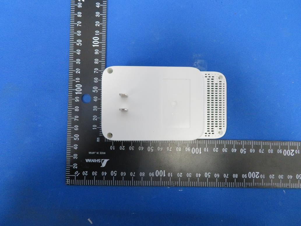
Jan 13, 2021AC750 Wi-Fi Range Extender, AC1200 Wi-Fi Range Extender
Equipment Class
DTS - Digital Transmission System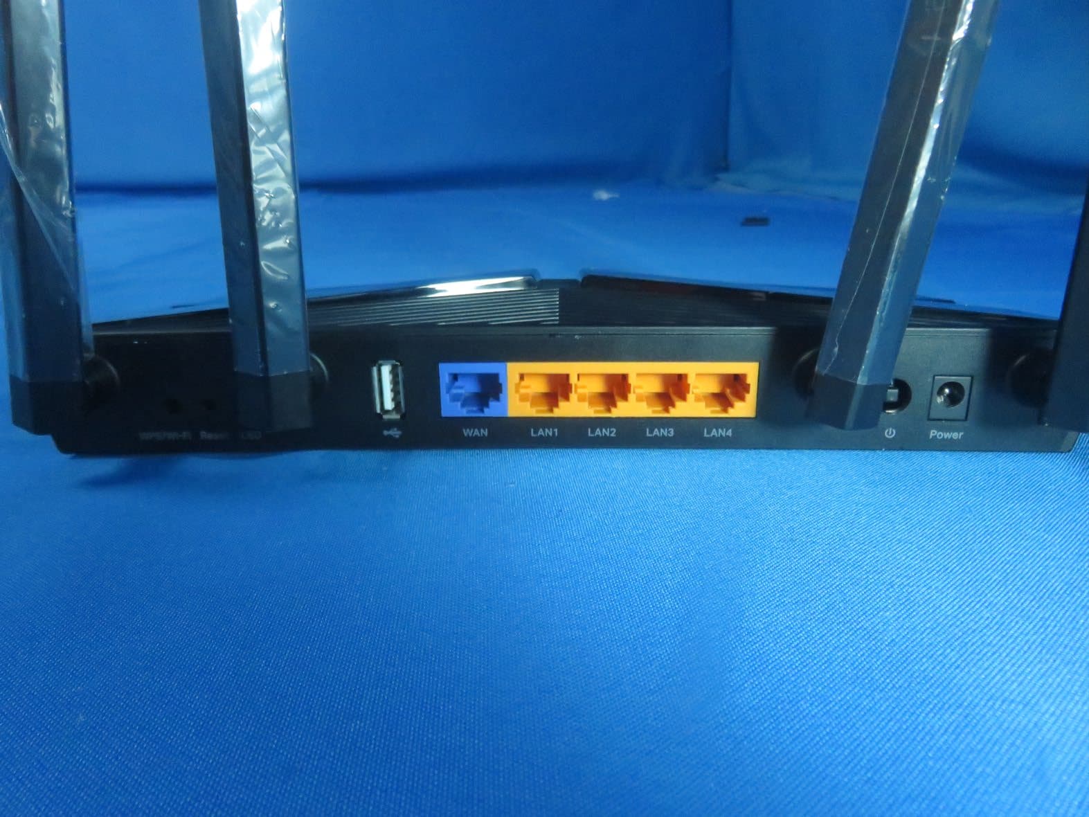
TE7AX20V2
Dec 22, 2020AX1800 Dual-Band Wi-Fi 6 Router
Equipment Class
DTS - Digital Transmission System
TE7EAP620HD
Dec 17, 2020AX1800 Wireless Dual-Band Gigabit Ceiling Mount Access Point
Equipment Class
NII - Unlicensed National Information Infrastructure TX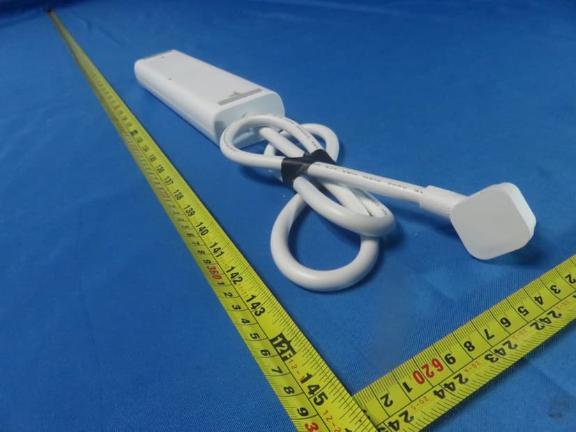
TE7KP303V2
Dec 15, 2020Kasa Smart Wi-Fi Power Strip, 3-Outlet
Equipment Class
DTS - Digital Transmission System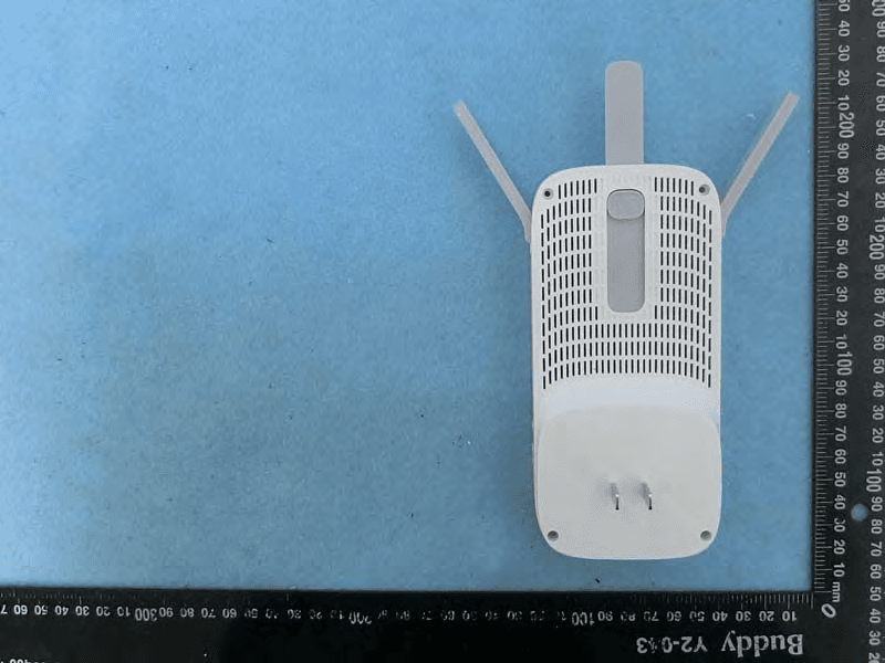
TE7RE550
Dec 03, 2020AC1750 Wi-Fi Range Extender, AC1900 MU-MIMO Wi-Fi Range Extender
Equipment Class
DTS - Digital Transmission System