TE7WA50XG54M Wireless Access Point
TP-Link Technologies Co., Ltd.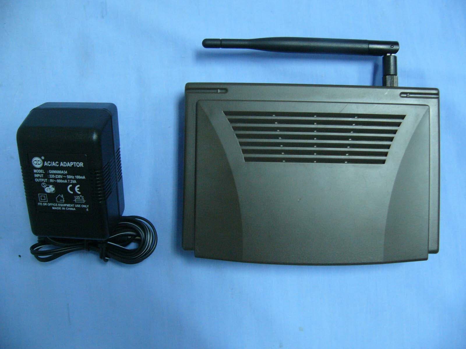
Click to zoom
Application Details
- Equipment Class
- DTS - Digital Transmission System
- Date of Grant
- Oct 21, 2006
- Application Purpose
- Original Equipment
- Date of Application
- Oct 18, 2006
- Equipment Note
- 54M Wireless Access Point
- Frequency Range
- 2412.00000000 - 2462.00000000
- Country
- China
Documents & Files
Document Text
Text extracted from the exhibit documents filed with the FCC. Open a document above to read the original.
Users Manual
User Guide TL-WA501G 54Mbps Wireless Access Point TM 2x to 3x eXtended Range 2.4GHz802.11g/b Rev:2.0 COPYRIGHT & TRADEMARKS Specifications are subject to change without notice. is a registered trademark of TP-LINK Technologies Co., Ltd. Other brands and product names are trademarks or registered trademarks of their respective holders. No part of the specifications may be reproduced in any form or by any means or used to make any derivative such as translation, transformation, or adaptation without permission from TP-LINK Technologies Co., Ltd. Copyright © 2006 TP-LINK Technologies Co., Ltd. All rights reserved. FCC STATEMENT This equipment has been tested and found to comply with the limits for a class B digital device, pursuant to part 15 of the FCC Rules. These limits are designed to provide reasonable protection against harmful interference in a residential installation. This equipment generates, uses and can radiate radio frequency energy and, if not installed and used in accordance with the instructions, may cause harmful interference to radio communications. However, there is no guarantee that interference will not occur in a particular installation. If this equipment does cause harmful interference to radio or television reception, which can be determined by turning the equipment off and on, the user is encouraged to try to correct the interference by one or more of the following measures: ¾ Reorient or relocate the receiving antenna. ¾ Increase the separation between the equipment and receiver. ¾ Connect the equipment into an outlet on a circuit different from that to which the receiver is connected. ¾ Consult the dealer or an experienced radio/TV technician for help. This device complies with Part 15 of the FCC Rules. Operation is subject to the following two conditions: (1) This device may not cause harmful interference. (2) This device must accept any interference received, including interference that may cause undesired operation. Changes or modifications to this unit not expressly approved by the party responsible for compliance could void the user's authority to operate the equipment. FCC RF Radiation Exposure Statement: This equipment complies with FCC RF radiation exposure limits set forth for an uncontrolled environment. This device and its antenna must not be co-located or operating in conjunction with any other antenna or transmitter. “To comply with FCC RF exposure compliance requirements, the antenna used for this transmitter must be installed to provide a separation distance of at least 20 cm from all persons and must not be co-located or operating in conjunction with any other antenna or transmitter”. CE Declaration of Conformity For the following equipment: TL-WA501G Is herewith confirmed to comply with the requirements set out in the Council Directive on the Approximation of the Laws of the Member States relating to Electromagnetic Compatibility (89/336/EEC), Low-voltage Directive (73/23/EEC) and the Amendment Directive (93/68/EEC), the procedures given in European Council Directive 99/5/EC and 89/3360EEC. The equipment was passed. The test was performed according to the following European standards: ¾ EN 300 328 V.1.4.1 (2003) ¾ EN 301 489-1 V.1.4.1 (2002) / EN 301 489-17 V.1.2.1 (2002) ¾ EN 60950-1: 2001 ¾ EN 55022: 1998 + A1: 2000 + A2: 2003 ¾ EN61000-3-2:2001 ¾ EN61000-3-3:2001 ¾ EN 55024: 1998 +A1: 2001 + A2: 2003 European standards dictate maximum radiated transmit power of 100mW EIRP and frequency range 2.400-2.4835GHz; In France, the equipment must be restricted to the 2.4465-2.4835GHz frequency range and must be restricted to indoor use. Package contents.............................................................................................................. 1 Chapter 1: About this Guide.............................................................................................. 2 1.1 Purposes.............................................................................................................. 2 1.2 Conventions......................................................................................................... 2 1.3 Overview of this User Guide................................................................................ 2 Chapter 2: Introduction...................................................................................................... 3 2.1 Overview of the AP.............................................................................................. 3 2.2 Features............................................................................................................... 3 2.3 Panel Layout........................................................................................................ 4 2.3.1 The Front Panel......................................................................................... 4 2.3.2 The Rear Panel.......................................................................................... 4 Chapter 3: Connecting the AP........................................................................................... 6 3.1 System Requirements.......................................................................................... 6 3.2 Installation Environment Requirements................................................................ 6 3.3 Connecting the AP............................................................................................... 6 Chapter 4: TCP/IP Configuration....................................................................................... 8 Chapter 5: Configuring the AP........................................................................................ 10 5.1 login................................................................................................................... 10 5.2 Status................................................................................................................. 10 5.3 Network....................................................…
Text truncated - open the document above for the full version.
Cover Letter(s)
Answer for ATCB Comments 10092006 6.) FCC is now requiring more details about the operational state when RF power and band edge measurements were performed. Please provide details about what data rates were used and what on/off transmitter pulse rates were tested. Answer:The worst case on 802.11b mode is 11Mbps, and 802.11g in 54bps, you may find the additional info on page 6 8.) Based upon the reported RF power and antenna gain, the expected peak radiated 3 meter field strength seen in your plots on pages 23 to 30 should be well over 120dBuV. [+23dBm + 2.5dBi EUT antenna – 11.7dB path loss for a 3M site] I question whether the device was properly peaked prior to testing the radiated band edge test. Please review your 15.205 radiated restricted band edge test. Answer:For the bandedge, the report shown all the possible worst data by the manner on tuning the turntable degree for the maximized emission. Further by accounting the antenna match and radiated measurement uncertainty entrusted that our measurements are getting in line on compliance each other. Thanks for your consideration.
Cover Letter(s)
American Telecommunications Certification Body Inc. 6731 Whittier Ave, McLean, VA 22101 October 9, 2006 RE: TP-Link Technologies FCC ID: TE7WA50XG I have a few comments on this Application. Depending on your responses, kindly understand there may be additional comments. 1.) There is some confusion in my mind about the component described as AR 2415 and AR 2315 in the Block Diagram, Schematics, and Operational Description. What is it and what does this do? Is there a problem with properly identifying this device? I am confused. 2.) Please note the Operational Description and Block Diagram are identical Exhibits. This is not allowed. Please provide unique Exhibits for both the Block Diagram and Operational Description. 3.) The label is incorrect. The proper format is “FCC ID:” and not “FCC Id:”. Please revise. 4.) I do not see required 15.19(a)(3) language on this product. Since this device is “larger than the palm of the hand”, then this required compliance language must appear on the device. Please review. 5.) Please review page 18 of the Manual. It appears that the end user is able to set regions/countries. This is absolutely not permitted under FCC rules. Only devices for which the end user has no ability to select operational characteristics which may allow the device to be set to frequency or power settings in violation of FCC rules are allowed for sale in USA. Please review. 6.) FCC is now requiring more details about the operational state when RF power and band edge measurements were performed. Please provide details about what data rates were used and what on/off transmitter pulse rates were tested. 7.) FCC is also recommending that RF Exposure reports be removed from all test reports and supplied as a separate RF Exposure exhibit. Please review and provide. 8.) Based upon the reported RF power and antenna gain, the expected peak radiated 3 meter field strength seen in your plots on pages 23 to 30 should be well over 120dBuV. [+23dBm + 2.5dBi EUT antenna – 11.7dB path loss for a 3M site] I question whether the device was properly peaked prior to testing the radiated band edge test. Please review your 15.205 radiated restricted band edge test. William H. Graff President and Director of Engineering mailto: [email protected] The items indicated above must be submitted before processing can continue on the above referenced application. Failure to provide the requested information may result in application termination. Correspondence should be considered part of the permanent submission and may be viewed from the Internet after a Grant of Equipment Authorization is issued. z Page 2 October 9, 2006 Please do not respond to this correspondence using the email reply button. In order for your response to be processed expeditiously, you must submit your documents through the AmericanTCB.com website. Also, please note that partial responses increase processing time and should not be submitted. Any questions about the content of this correspondence should be directed to the sender.
RF Exposure Info
RADIO FREQUENCY EXPOSURE LIMIT Systems operating under the provisions of this section shall be operated in a manner that ensures that the public is not exposed to radio frequency energy levels in excess of the Commission's guidelines. See §15.247(b)(4) and §1.1307(b)(1) of this chapter. EUT Specification EUT 54M Wireless Access Point Frequency band (Operating) WLAN: 2.412GHz ~ 2.462GHz WLAN: 5.18GHz ~ 5.32GHz / 5.50GHz ~ 5.70GHz WLAN: 5.745GHz ~ 5825GHz Others Device category Portable (<20cm separation) Mobile (>20cm separation) Others __________________________ Exposure classification Occupational/Controlled exposure (S = 5mW/cm 2 ) General Population/Uncontrolled exposure (S=1mW/cm 2 ) Antenna diversity Single antenna Multiple antennas Tx diversity Rx diversity Tx/Rx diversity Max. output power 23.12 dBm (205.12mW) Antenna gain (Max) 4 dBi (Numeric gain: 2.51) Evaluation applied MPE Evaluation SAR Evaluation Note: 1. The maximum output power is 23.12 dBm (205.12mW) at 2462MHz (with 2.51 numeric antenna gain.) 2. For mobile or fixed location transmitters, no SAR consideration applied. The minimum separation generally be used is at least 20 cm, even if the calculations indicate that the MPE distance would be lesser. TEST RESULTS No non-compliance noted Calculation Given d GP E ×× = 30 & 3770 2 E S= Where E = Field Strength in Volts / meter P = Power in Watts G=Numeric antenna gain d=Distance in meters S=Power Density in milliwatts / square centimeter Combining equations and re-arranging the terms to express the distance as a function of the remaining variables yields: S GP d × ×× = 3770 30 Changing to units of mW and cm, using: P (mW) = P (W) / 1000 and d (cm) =100 * d (m) Yields S GP S GP d × ×= × ×× ×=282.0 3770 )1000/(30 100 Where d = distance in cm P = Power in mW G = Numeric antenna gain S = Power Density in mW / cm^2 Substituting the logarithmic form of power and gain using: P (mW) = 10 ^ (P (dBm) / 10) and G (numeric) = 10 ^ (G (dBi) / 10) Yields 20 10 282.0 20 )(GP d + ×= Equation 1 Where d = MPE safe distance in cm P = Power in dBm G = Antenna Gain in dBi S = Power Density Limit in mW / cm^2 Maximum Permissible Exposure EUT output power = 205.12 mW Antenna Gain = 2.51 S = 1.0 mW / cm^2 from 1.1310 Table 1 Substituting these parameters into the above Equation 1: Æ MPE = 2 cmmW / 96.31 4 = × π GP (For mobile or fixed location transmitters, the minimum separation distance is 20 cm, even if calculations indicate that the MPE distance would be less.)
Test Report
Compliance Certification Services (Shenzhen) Inc. Report No: SZ060727B01-RP FCC ID: TE7WA50XG Date of Issue: September 26, 2006 Note: This report shall not be reproduced except in full, without the written approval of Compliance Certification Services Inc. This document may be altered or revised by Compliance Certification Services Inc. personnel only, and shall be noted in the revision section of the document. Page 1 of 59 FCC 47 CFR PART 15 SUBPART C TEST REPORT For 54M Wireless Access Point Model: TL-WA501G Trade Name: TP-LINK Prepared for TP-LINK TECHNOLOGIES CO., LTD. BUILDING 7, SECTION 2, HONGHUALING INDUSTRIAL PARK, XILI, NANSHAN DISTRICT, SHENZHEN, P.R.C. Prepared by COMPLIANCE CERTIFICATION SERVICES (SHENZHEN) INC. NO. 5, JINAO INDUSTRIAL PARK, NO. 35 JUKENG ROAD, DASHUIKENG VILLAGE, GUANLAN TOWN, BAOAN DISTRICT, SHENZHEN, CHINA TEL: 86-755-28055000 FAX: 86-755-28055221 LAB CODE:200577-0 Compliance Certification Services (Shenzhen) Inc. Report No: SZ060727B01-RP FCC ID: TE7WA50XG Date of Issue: September 26, 2006 Page 2 TABLE OF CONTENTS 1. TEST RESULT CERTIFICATION....................................................................................................3 2. EUT DESCRIPTION ...........................................................................................................................4 3. TEST METHODOLOGY ....................................................................................................................5 3.1 EUT CONFIGURATION........................................................................................................................5 3.2 EUT EXERCISE....................................................................................................................................5 3.3 GENERAL TEST PROCEDURES.............................................................................................................5 3.4 FCC PART 15.205 RESTRICTED BANDS OF OPERATIONS.........................................................6 3.5 DESCRIPTION OF TEST MODES...........................................................................................................6 4. INSTRUMENT CALIBRATION........................................................................................................7 5. FACILITIES AND ACCREDITATIONS ..........................................................................................8 5.1 FACILITIES ........................................................................................................8 5.2 EQUIPMENT........................................................................................................................................8 5.3 LABORATORY ACCREDITATIONS AND LISTING..................................................................................8 6. SETUP OF EQUIPMENT UNDER TEST .........................................................................................9 6.1 SETUP CONFIGURATION OF EUT.........................................................................................................9 6.2 SUPPORT EQUIPMENT .................................................................................................................9 7. FCC PART 15.247 REQUIREMENTS.............................................................................................10 7.1 6DB BANDWIDTH.............................................................................................................................10 7.2 PEAK POWER....................................................................................................................................16 7.3 BAND EDGES MEASUREMENT ................................................................................................22 7.4 PEAK POWER SPECTRAL DENSITY....................................................................................................31 7.5 SPURIOUS EMISSIONS.................................................................................................................37 7.6 POWERLINE CONDUCTED EMISSIONS..............................................................................................54 APPENDIX 1 PHOTOGRPHS OF TEST SETUP .................................................................................58 Compliance Certification Services (Shenzhen) Inc. Report No: SZ060727B01-RP FCC ID: TE7WA50XG Date of Issue: September 26, 2006 Page 3 1. TEST RESULT CERTIFICATION Applicant: TP-LINK TECHNOLOGIES CO., LTD. BUILDING 7, SECTION 2, HONGHUALING INDUSTRIAL PARK, XILI, NANSHAN DISTRICT, SHENZHEN, P.R.C. Equipment Under Test: 54M Wireless Access Point Trade Name: TP-LINK Model: TL-WA501G Date of Test: July 27-September 26, 2006 APPLICABLE STANDARDS STANDARD TEST RESULT FCC Part 15 Subpart C No non-compliance noted We hereby certify that: The above equipment was tested by Compliance Certification Services (Shenzhen) Inc. The test data, data evaluation, test procedures, and equipment configurations shown in this report were made in accordance with the procedures given in ANSI C63.4: 2003 and the energy emitted by the sample EUT tested as described in this report is in compliance with the requirements of FCC Rules Part 15.207, 15.209, 15.247. The test results of this report relate only to the tested sample EUT identified in this report. Approved by: Tested By: Henry Ding Reviewed By: Harris Lai / General Manager Eric Wong / Assistant manager COMPLIANCE CERTIFICATION COMPLIANCE CERTIFICATION SERVICES (SHENZHEN) INC. SERVICES (SHENZHEN) INC. Compliance Certification Services (Shenzhen) Inc. Report No: SZ060727B01-RP FCC ID: TE7WA50XG Date of Issue: September 26, 2006 Page 4 2. EUT DESCRIPTION Product 54M Wireless Access Point Trade Name TP-LINK Model Number TL-WA501G Model Difference N/A Power Supply Powered by the adapter Frequency Range 802.11b mode: 2412 ~ 2462 MHz 802.11g mode: 2412 ~ 2462 MHz Transmit Power 802.11b mode: 23.12 dBm 802.11g mode: 22.77 dBm Modulation Technique 802.11b: DSSS (CCK; DQPSK; DB…
Text truncated - open the document above for the full version.
Test Setup Photos
Compliance Certification Services (Shenzhen) Inc. Report No: SZ060727B01-RP FCC ID: TE7WA50XG Date of Issue: August 24, 2006 Page 66 APPENDIX 1 PHOTOGRPHS OF TEST SETUP LINE CONDUCTED EMISSION TEST Compliance Certification Services (Shenzhen) Inc. Report No: SZ060727B01-RP FCC ID: TE7WA50XG Date of Issue: August 24, 2006 Page 67 RADIATED EMISSION TEST
Contact Information
Applicant
Jing Huang(Regulatory Compliance Manager)
Technical Contact
TP-Link Technologies Co., LtdSai Li
[email protected]+86 755 26525554
3/F, Building R1-B, Hi-Tech Industrial Park · Shenzhen, Guangdong · China
Test Firm
Compliance Certification Services (Shenzhen) Inc.Clinton Kao
Technical Specifications
| # | Rule Parts | Frequency Range | Power Output |
|---|---|---|---|
| 1 | 15C | 2.41 GHz - 2.46 GHz | 205.00 mW |
Other Applications from TP-Link Technologies Co., Ltd.
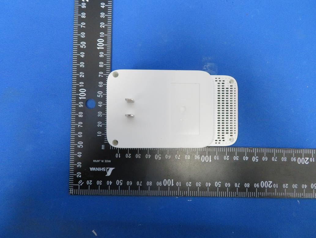
TE7RE230V2
Jan 13, 2021AC750 Wi-Fi Range Extender, AC1200 Wi-Fi Range Extender
Equipment Class
DTS - Digital Transmission System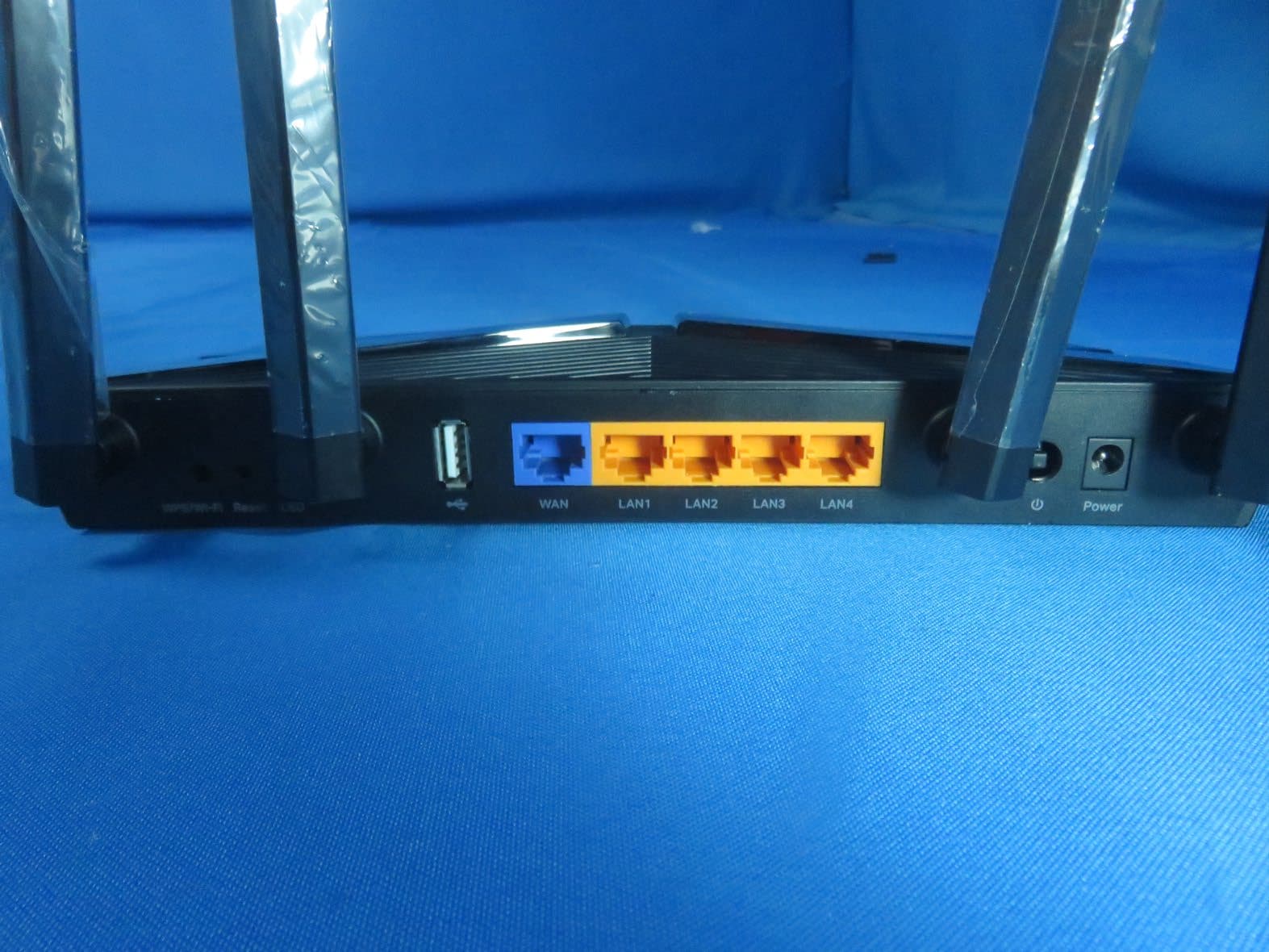
TE7AX20V2
Dec 22, 2020AX1800 Dual-Band Wi-Fi 6 Router
Equipment Class
DTS - Digital Transmission System
TE7EAP620HD
Dec 17, 2020AX1800 Wireless Dual-Band Gigabit Ceiling Mount Access Point
Equipment Class
NII - Unlicensed National Information Infrastructure TX
TE7KP303V2
Dec 15, 2020Kasa Smart Wi-Fi Power Strip, 3-Outlet
Equipment Class
DTS - Digital Transmission System
TE7RE550
Dec 03, 2020AC1750 Wi-Fi Range Extender, AC1900 MU-MIMO Wi-Fi Range Extender
Equipment Class
DTS - Digital Transmission System