TE7WN310G54M Wireless Cardbus Adapter
TP-Link Technologies Co., Ltd.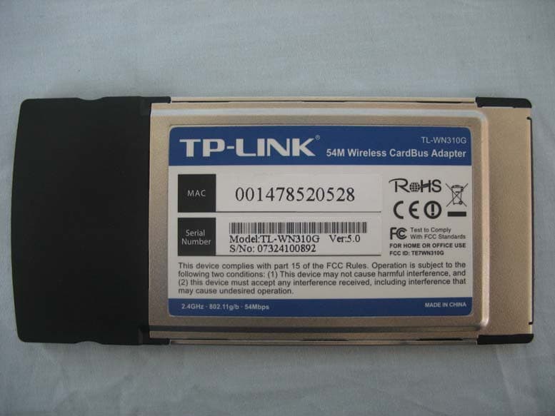
Click to zoom
Application Details
- Equipment Class
- DTS - Digital Transmission System
- Date of Grant
- May 20, 2007
- Application Purpose
- Original Equipment
- Date of Application
- May 15, 2007
- Equipment Note
- 54M Wireless Cardbus Adapter
- Frequency Range
- 2412.00000000 - 2462.00000000
- Country
- China
Documents & Files
Document Text
Text extracted from the exhibit documents filed with the FCC. Open a document above to read the original.
Users Manual
COPYRIGHT & TRADEMARKS Specifications are subject to change without notice. is a registered trademark of TP-LINK TECHNOLOGIES CO., LTD. Other brands and product names are trademarks or registered trademarks of their respective holders. No part of the specifications may be reproduced in any form or by any means or used to make any derivative such as translation, transformation, or adaptation without permission from TP-LINK TECHNOLOGIES CO., LTD. Copyright © 2007 TP-LINK TECHNOLOGIES CO., LTD. All rights reserved. FCC STATEMENT This equipment has been tested and found to comply with the limits for a Class B digital device, pursuant to part 15 of the FCC Rules. These limits are designed to provide reasonable protection against harmful interference in a residential installation. This equipment generates, uses and can radiate radio frequency energy and, if not installed and used in accordance with the instructions, may cause harmful interference to radio communications. However, there is no guarantee that interference will not occur in a particular installation. If this equipment does cause harmful interference to radio or television reception, which can be determined by turning the equipment off and on, the user is encouraged to try to correct the interference by one or more of the following measures: • Reorient or relocate the receiving antenna. • Increase the separation between the equipment and receiver. • Connect the equipment into an outlet on a circuit different from that to which the receiver is connected. • Consult the dealer or an experienced radio/ TV technician for help. This device complies with part 15 of the FCC Rules. Operation is subject to the following two conditions: 1) This device may not cause harmful interference. 2) This device must accept any interference received, including interference that may cause undesired operation. FCC Radiation Exposure Statement This device has been tested for compliance with FCC RF Exposure (SAR) limits in the typical laptop computer configuration and this device can be used in desktop or laptop computers with side mounted PCMCIA slots. This device cannot be used with handheld PDAs (personal digital assistants). This device and its antenna must not be co-located or operated in conjunction with any other antenna or transmitter. CE Mark Warning This is a class B product. In a domestic environment, this product may cause radio interference, in which case the user may be required to take adequate measures. Package Contents 1 Chapter1. Introduction.................................................................................................. 2 1.1 Overview of the product................................................................................... 2 1.2 Features .......................................................................................................... 2 1.3 LED Status....................................................................................................... 2 Chapter2. Installation Guide ......................................................................................... 3 2.1 Hardware Installation ....................................................................................... 3 2.2 Software Installation ........................................................................................ 3 2.2.1 Overview .............................................................................................. 3 2.2.2 Software Installation for Windows 2000................................................ 3 Chapter3. Configuration ............................................................................................... 9 3.1 Current Status.................................................................................................. 9 3.2 Profile Management....................................................................................... 10 3.2.1 Add or Modify a Configuration Profile ..................................................11 3.2.2 Remove a profile ................................................................................ 14 3.2.3 Switch another Profile......................................................................... 14 3.2.4 Export a Profile ................................................................................... 15 3.2.5 Import a Profile ................................................................................... 15 3.2.6 Scan Available Networks .................................................................... 15 3.2.7 Auto Profile Selection Management ................................................... 16 3.3 Diagnostics .................................................................................................... 17 3.3.1 Check Driver Information .................................................................... 17 3.3.2 Check Receive and Transmit Statistical Information........................... 18 Appendix A: Specifications .............................................................................................. 19 Appendix B: Glossary...................................................................................................... 20 Appendix C: Contact Information .................................................................................... 22 TL-WN310G 54M Wireless Adapter User Guide - 1 - Package Contents The following contents should be found in your box: ¾ One TL-WN310G Wireless Adapter ¾ Quick Installation Guide ¾ One Resource CD for TL-WN310G, including: • TP-LINK Wireless Client Utility (TWCU) and Drivers • User Guide • Other Helpful Information Note: If any of the listed contents are damaged or missing, please contact the retailer from whom you purchased the TL-WN310G Wireless Adapter for assistance. TL-WN310G 54M Wireless Adapter User Guide - 2 - Chapter1. Introduction 1.1 Overview of the product The TP-LINK 54M Wireless Adapter TL-WN310G gives you the flexibility to install your PC or notebook PC in the most…
Text truncated - open the document above for the full version.
Cover Letter(s)
American Telecommunications Certification Body Inc. 6731 Whittier Ave, McLean, VA 22101 May 1, 2007 RE: FCC ID: TE7WN310G_ATCB004856 Attention: Sai Li I have a few comments on this Application. Please note that further comments may arise in response to answers provided to the questions below. 1. Please note that the conducted power levels reported in the SAR report are significantly less than those reported in the EMC report. For example, the EMC report shows a max conducted power of 25.34dBm in 802.11g mode while the SAR report shows a max conducted power of only 18dBm in the same mode. This is a 7+dB difference. The 802.11b mode is a little better with the highest EMC conducted power was recorded as 20.81dBm while the highest conducted power in the same mode in the SAR report is only recorded at 19dBm and a 1.8dB difference. This is unacceptable. Please retest SAR using the 25.34 max power level as recorded in the EMC report. Please remember that the difference should not be greater than approximately 0.5dBm for conducted power. 2. Please note that the test data plots do not appear to provide the serial number of the probe. Please provide this information and please verify that the probe used is the same probe for which calibration data has been provided. Dennis Ward mailto:[email protected] The items indicated above must be submitted before processing can continue on the above referenced application. Failure to provide the requested information may result in application termination. Correspondence should be considered part of the permanent submission and may be viewed from the Internet after a Grant of Equipment Authorization is issued. Please do not respond to this correspondence using the email reply button. In order for your response to be processed expeditiously, you must submit your documents through the AmericanTCB.com website. Also, please note that partial responses increase processing time and should not be submitted. Any questions about the content of this correspondence should be directed to the sender.
Cover Letter(s)
American Telecommunications Certification Body Inc. 6731 Whittier Ave, McLean, VA 22101 May 10, 2007 RE: Additional comments due to original responses for FCC ID: TE7WN310G_ATCB004856 Attention: Sai Li I have a few comments on this Application. Please note that further comments may arise in response to answers provided to the questions below. 1. Please note that page 5 of the SAR report lists 2412 to 2483MHz. Please note that this is not a legal band of operation for this device in the US. Please correct the SAR report page to show the proper frequency band of operation (i.e. 2412-2462MHz). 2. Please note that the new report shows the exact same SAR values even though the power levels listed are up to 2+dB difference. Please explain how this is possible and please properly address items1 of the original comments letter. Please see page 20 of the revised and original SAR reports. Dennis Ward mailto:[email protected] The items indicated above must be submitted before processing can continue on the above referenced application. Failure to provide the requested information may result in application termination. Correspondence should be considered part of the permanent submission and may be viewed from the Internet after a Grant of Equipment Authorization is issued. Please do not respond to this correspondence using the email reply button. In order for your response to be processed expeditiously, you must submit your documents through the AmericanTCB.com website. Also, please note that partial responses increase processing time and should not be submitted. Any questions about the content of this correspondence should be directed to the sender.
External Photos
54M Wireless Cardbus Adapter (M/N: TL-WN310G) ¾ EUT Photograph – External Photographs (1) EUT Photo (2) EUT Photo (3) EUT Photo
ID Label/Location Info
Label&Location
Internal Photos
54M Wireless Cardbus Adapter (M/N: TL-WN310G) ¾ EUT Photograph - Internal Photographs (1) EUT Photo (2) EUT Photo
RF Exposure Info
Report No:074L143-HPTWP05V01 Page: 1 of 22 Version:1.0 SAR Test Report Product Name :54M Wireless Cardbus Adapter Model No. :TL-WN310G Applicant : TP-LINK Technologies Co., Ltd. Address : Building 7, Section 2, Honghualing Industrial Park, Xili, Nanshan District, Shenzhen, P.R.C. Date of Receipt :2007/04/17 Issued Date :2007/04/24 Report No. :074L143-HPTWP05V01 The test results relate only to the samples tested. The test report shall not be reproduced except in full without the written approval of QuieTek Corporation. Report No:074L143-HPTWP05V01 Page: 2 of 22 Version:1.0 Test Report Certification Issued Date: 2007/04/24 Report No.: 074143-HPTWP05V01 The test results relate only to the samples tested. The test report shall not be reproduced except in full without the written approval of QuieTek Corporation. Product Name : 54M Wireless Cardbus Adapter Applicant : TP-LINK Technologies Co., Ltd. Address : Building 7, Section 2, Honghualing Industrial Park, Xili, Nanshan District, Shenzhen, P.R.C. Manufacturer : TP-LINK Technologies Co., Ltd. Model No. : TL-WN310G FCC ID : KA2WA110A1 Trade Name : TP-LINK Applicable Standard : FCC Oet65 Supplement C June 2001 Test Result : Max. SAR Measurement (1g) 802.11b: 0.448 W/kg 802.11g: 0.458 W/kg Application Type Certification Documented By : (Engineering Adm. Assistant / Eva Huang) Tested By : (Senior Engineer / Shine Hsu) Approved By : (President / Gene Chang) Report No:074L143-HPTWP05V01 Page: 3 of 22 Version:1.0 TABLE OF CONTENTS Description Page 1. General Information.............................................................................. 5 1.1 EUT Description ............................................................................................................5 1.2 Test Environment ...........................................................................................................5 2. SAR Measurement System .................................................................. 6 2.1 ALSAS-10U System Description .................................................................................. 6 2.1.1 Applications ................................................................................................................ 6 2.1.2 Area Scans................................................................................................................... 6 2.1.3 Zoom Scan (Cube Scan Averaging)............................................................................ 7 2.1.4 ALSAS-10U Interpolation and Extrapolation Uncertainty......................................... 7 2.2 Isotropic E-Field Probe .................................................................................................. 7 2.2.1 Isotropic E-Field Probe Specification ......................................................................... 9 2.3 Boundary Detection Unit and Probe Mounting Device ................................................. 9 2.4 Daq-Paq (Analog to Digital Electronics) ..................................................................... 10 2.5 Axis Articulated Robot ................................................................................................ 10 2.6 ALSAS Universal Workstation.................................................................................... 11 2.7 Universal Device Positioner......................................................................................... 11 2.8 Phantom Types............................................................................................................. 11 2.8.1 APREL SAM Phantoms ........................................................................................... 12 2.8.2 APREL Laboratories Universal Phantom ................................................................. 12 3. Tissue Simulating Liquid ................................................................... 13 3.1 The composition of the tissue simulating liquid .......................................................... 13 3.2 Tissue Calibration Result ............................................................................................. 13 3.3 Tissue Dielectric Parameters for Head and Body Phantoms ....................................... 14 4. SAR Measurement Procedure ........................................................... 15 4.1 SAR System Validation................................................................................................ 15 4.1.1 Validation Dipoles..................................................................................................... 15 4.1.2 Validation Result ....................................................................................................... 15 4.2 SAR Measurement Procedure ...................................................................................... 16 5. SAR Exposure Limits ......................................................................... 17 6. Test Equipment List............................................................................ 18 7. Measurement Uncertainty .................................................................. 19 8. Test Results ......................................................................................... 20 Report No:074L143-HPTWP05V01 Page: 4 of 22 Version:1.0 8.1 SAR Test Results Summary ......................................................................................... 20 Appendix A. SAR System Validation Data........................................................................ 22 Appendix B. SAR measurement Data................................................................................ 22 Appendix C. Test Setup Photographs & EUT Photographs............................................... 22 Appendix D. Probe Calibration Data ................................................................................. 22 Appendix E. Dipole Calibration Data ................................................................................ 22 Report No:074L143-HPTWP…
Text truncated - open the document above for the full version.
Test Report
Test Report Product Name : 54M Wireless Cardbus Adapter Model No. : TL-WN310G FCC ID : TE7WN310G Applicant : TP-LINK Technologies Co., Ltd Address : Building 7, Section 2, Honghualing Industrial Park, Xili, Nanshan District, Shenzhen, P.R.C. Date of Receipt : 2007/04/11 Issued Date : 2007/04/25 Report No. : 074S033-RF-US-P05V01 The test results relate only to the samples tested. The test results shown in the test report are traceable to the national/international standard through the calibration of the equipment and evaluated measurement uncertainty herein. This report must not be used to claim product endorsement by CNLA, NVLAP, NIST or any agency of the Government. The test report shall not be reproduced except in full without the written approval of QuieTek Corporation. Report No: 074S033-RF-US-P05V01 Page: 2 of 115 Test Report Certification Issued Date : 2007/04/25 Report No. : 074S033-RF-US-P05V01 Product Name : 54M Wireless Cardbus Adapter Applicant : TP-LINK Technologies Co., Ltd Address : Building 7, Section 2, Honghualing Industrial Park, Xili, Nanshan District, Shenzhen, P.R.C. Manufacturer : TP-LINK Technologies Co., Ltd Model No. : TE7WN310G FCC ID : TL7WN310G EUT Voltage : DC 3.3V Trade Name : TP-LINK Applicable Standard : FCC CFR Title 47 Part 15 Subpart C: 2006 ANSI C63.4: 2003 Test Result : Complied Performed Location : SuZhou EMC laboratory No.99 Hongye Rd., Suzhou Industrial Park Loufeng Hi-Tech Development Zone., SuZhou, China TEL: +86-512-6251-5088 / FAX:+86-512-6251-5098 FCC Registration number: 800392 Documented By : ( Mandy Liu ) Reviewed By : ( Dream Cao ) Approved By : ( Gene Chang ) Report No: 074S033-RF-US-P05V01 Page: 3 of 115 Laboratory Information We , QuieTek Corporation, are an independent EMC and safety consultancy that was established the whole facility in our laboratories. The test facility has been accredited by the following accreditation Bodies in compliance with ISO 17025, EN 45001 and Guide 25: The related certificate for our laboratories about the test site and management system can be downloaded from QuieTek Corporation’s Web Site : http://tw.quietek.com/modules/myalbum/ The address and introduction of QuieTek Corporation’s laboratories can be founded in our Web site : http://www.quietek.com/ If you have any comments, Please don’t hesitate to contact us. Our contact information is as below: HsinChu Testing Laboratory : No.75-2, 3rd Lin, Wangye Keng, Yonghxing Tsuen, Qionglin Shiang, Hsinchu County 307, Taiwan, R.O.C. TEL:+886-3-592-8858 / FAX:+886-3-592-8859 E-Mail : [email protected] LinKou Testing Laboratory : No. 5-22, Ruei-Shu Valley, Ruei-Ping Tsuen, Lin-Kou Shiang, Taipei, Taiwan, R.O.C. TEL : 886-2-8601-3788 / FAX : 886-2-8601-3789 E-Mail : [email protected] Suzhou Testing Laboratory : No.99 Hongye Rd., Suzhou Industrial Park Loufeng Hi-Tech Development Zone., SuZhou, China TEL : +86-512-6251-5088 / FAX : 86-512-6251-5098 E-Mail : [email protected] Taiwan R.O.C. : BSMI, DGT, CNLA Germany : TUV Rheinland Norway : Nemko, DNV USA : FCC, NVLAP Japan : VCCI 0914 1313 1596 Report No: 074S033-RF-US-P05V01 Page: 4 of 115 TABLE OF CONTENTS Description Page 1. General Information .................................................................................................... 6 1.1. EUT Description...................................................................................................... 6 1.2. Mode of Operation .................................................................................................. 8 1.3. Tested System Details ............................................................................................ 9 1.4. Configuration of Tested System............................................................................ 10 1.5. EUT Exercise Software......................................................................................... 11 2. Technical Test ........................................................................................................... 12 2.1. Summary of Test Result........................................................................................ 12 2.2. Test Environment .................................................................................................. 13 3. Conducted Emission................................................................................................. 14 3.1. Test Equipment .....................................................................................................14 3.2. Test Setup............................................................................................................. 14 3.3. Limit... ..................................................................................................................15 3.4. Test Procedure ..................................................................................................... 15 3.5. Uncertainty ........................................................................................................... 15 3.6. Test Result ............................................................................................................ 16 3.7. Test Photograph ................................................................................................... 28 4. Radiated Emission .................................................................................................... 30 4.1. Test Equipment .....................................................................................................30 4.2. Test Setup............................................................................................................. 30 4.3. Limit... ..................................................................................................................31 4.4. Test Procedure ..................................................................................................... 32 4.5. Uncertainty .............................................................................…
Text truncated - open the document above for the full version.
Test Setup Photos
54M Wireless Cardbus Adapter (M/N: TL-WN310G) ¾ Test Setup Photographs Test Mode: Mode 1: Transmit by 802.11b Description: Front View of Conduction Test Test Mode: Mode 1: Transmit by 802.11b Description: Back View of Conduction Test Test Mode: Mode 2: Transmit by 802.11g Description: Front View of Conduction Test Test Mode: Mode 2: Transmit by 802.11g Description: Back View of Conduction Test Test Mode: Mode 1: Transmit by 802.11b Description: Front View of Radiated Test for Under 1GHz Test Mode: Mode 1: Transmit by 802.11b Description: Back View of Radiated Test for Under 1GHz Test Mode: Mode 1: Transmit by 802.11b Description: Front View of Radiated Test for Above 1GHz Test Mode: Mode 1: Transmit by 802.11b Description: Back View of Radiated Test for Above 1GHz Test Mode: Mode 2: Transmit by 802.11g Description: Front View of Radiated Test for Under 1GHz Test Mode: Mode 2: Transmit by 802.11g Description: Back View of Radiated Test for Under 1GHz Test Mode: Mode 2: Transmit by 802.11g Description: Front View of Radiated Test for Above 1GHz Test Mode: Mode 2: Transmit by 802.11g Description: Back View of Radiated Test for Above 1GHz
Contact Information
Applicant
Jing Huang(Regulatory Compliance Manager)
Test Firm
DEKRA Testing and Certification (Suzhou) Co., Ltd.Jerry Pan
Technical Specifications
| # | Rule Parts | Frequency Range | Power Output |
|---|---|---|---|
| 1 | 15C | 2.41 GHz - 2.46 GHz | 342.00 mW |
Other Applications from TP-Link Technologies Co., Ltd.
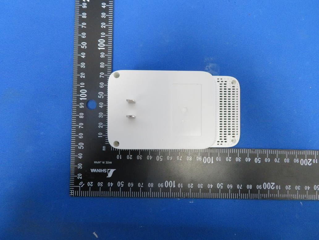
TE7RE230V2
Jan 13, 2021AC750 Wi-Fi Range Extender, AC1200 Wi-Fi Range Extender
Equipment Class
DTS - Digital Transmission System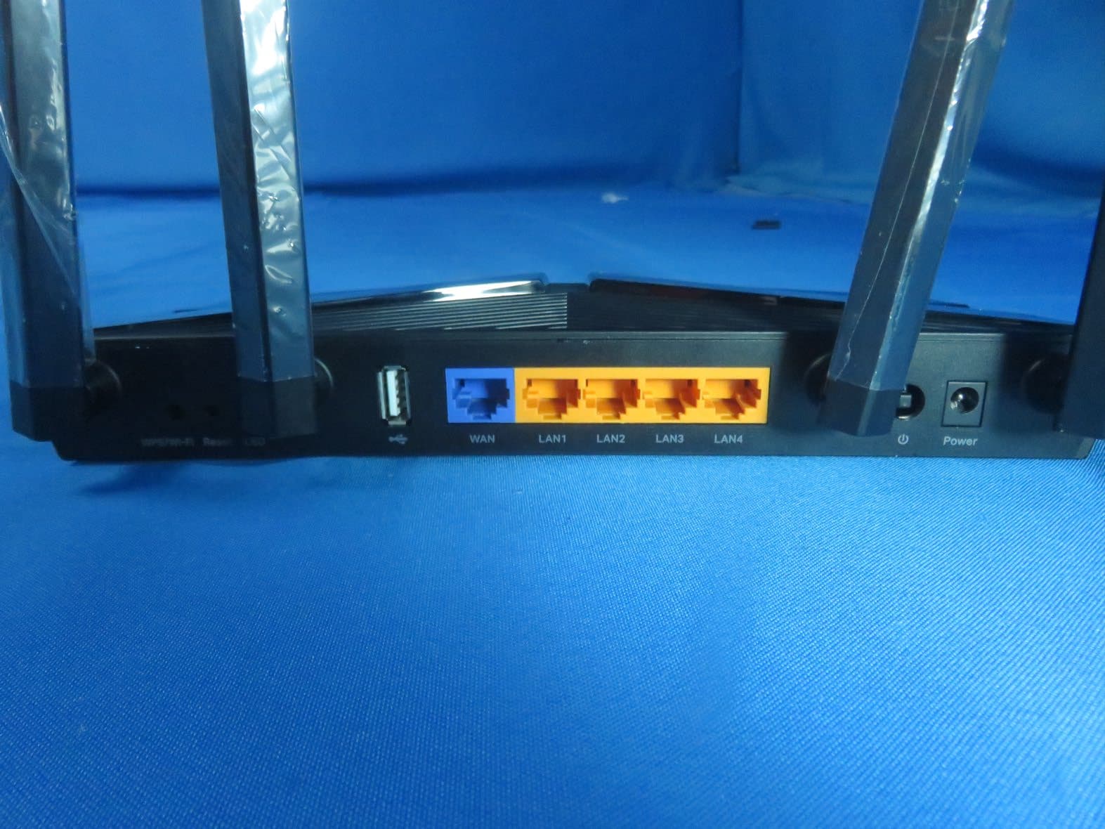
TE7AX20V2
Dec 22, 2020AX1800 Dual-Band Wi-Fi 6 Router
Equipment Class
DTS - Digital Transmission System
TE7EAP620HD
Dec 17, 2020AX1800 Wireless Dual-Band Gigabit Ceiling Mount Access Point
Equipment Class
NII - Unlicensed National Information Infrastructure TX
TE7KP303V2
Dec 15, 2020Kasa Smart Wi-Fi Power Strip, 3-Outlet
Equipment Class
DTS - Digital Transmission System
TE7RE550
Dec 03, 2020AC1750 Wi-Fi Range Extender, AC1900 MU-MIMO Wi-Fi Range Extender
Equipment Class
DTS - Digital Transmission System