TE7X20AX1800 Whole Home Mesh Wi-Fi System
TP-Link Technologies Co., Ltd.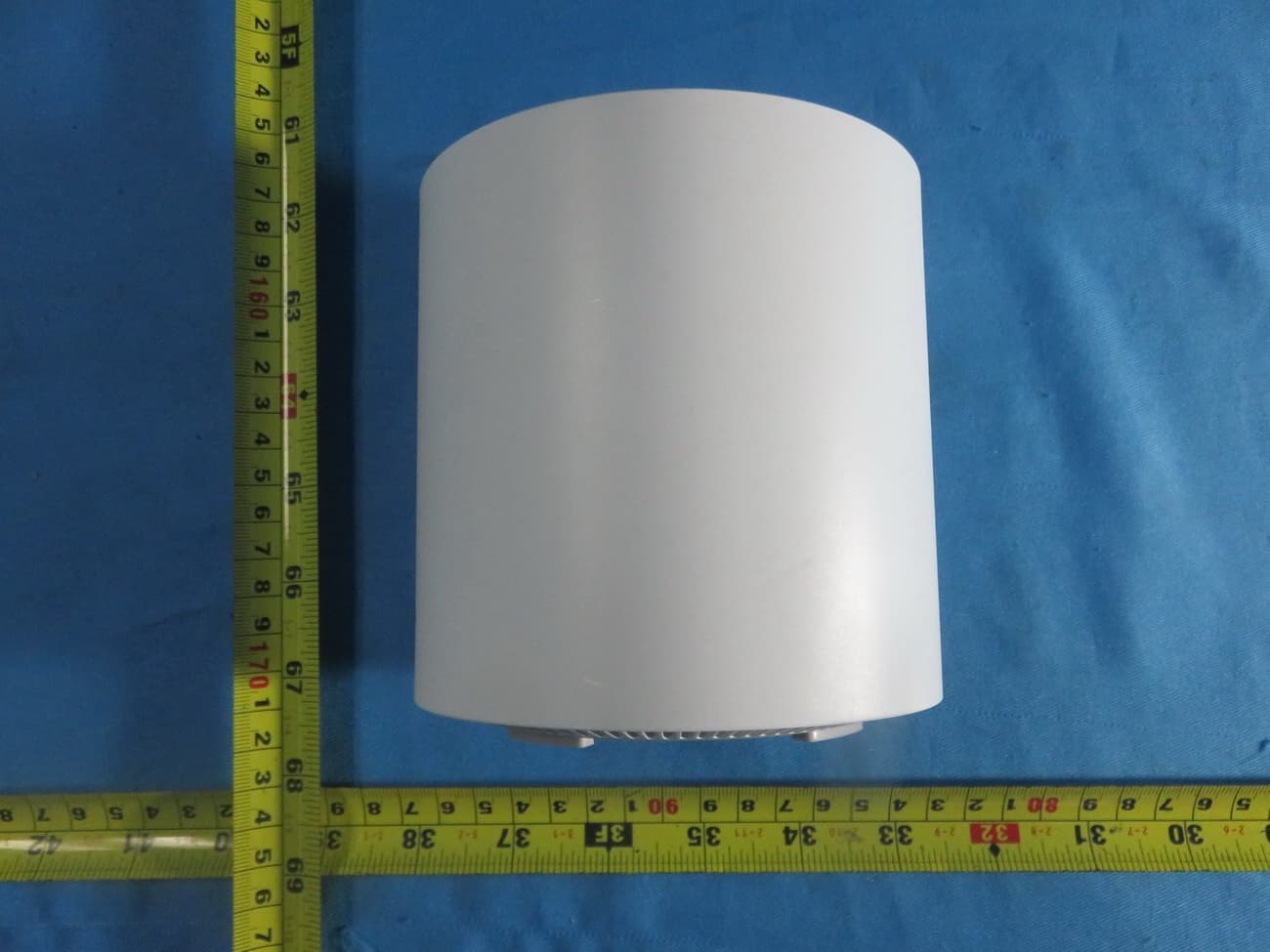
Click to zoom
Application Details
- Equipment Class
- NII - Unlicensed National Information Infrastructure TX
- Date of Grant
- Jan 16, 2020
- Application Purpose
- Original Equipment
- Date of Application
- Jan 13, 2020
- Equipment Note
- AX1800 Whole Home Mesh Wi-Fi System
- Frequency Range
- 5150.00000000 - 5250.00000000
- Country
- China
Documents & Files
Document Text
Text extracted from the exhibit documents filed with the FCC. Open a document above to read the original.
Users Manual
Whole Home Mesh Wi-Fi System Seamless Roaming | Parental Controls | Easy Setup User Guide AX1800 Whole Home Mesh Wi-Fi System Deco X20 1910012699 REV1.0.0 Contents About This Guide ····················································1 Appearance ·······························································2 Set Up Your Deco ···················································3 Dashboard ··································································5 Wi-Fi Settings····························································6 Parental Controls ····················································7 Advanced Features ···············································8 Update Decos ························································12 Managers ··································································13 Authentication ························································14 1 About This Guide This guide provides a brief introduction to Deco Whole Home Mesh Wi-Fi System and the Deco app, as well as regulatory information. Please note that features of Deco may vary slightly depending on the model and software version you have, and on your location, language and internet service provider. All images, parameters and descriptions documented in this guide are used for demonstration only. Conventions In this guide, the following conventions are used: Convention Description Deco Stands for Deco Whole Home Mesh Wi-Fi System/Unit. Underline Hyperlinks are in teal and underlined. You can click to redirect to a website or a specific section. Teal Key information appears in teal, including management page text such as menus, items, buttons and so on. Note: Ignoring this type of note might result in a malfunction or damage to the device. Tips: Indicates important information that helps you make better use of your device. More Info • Specific product information can be found on the product page at https://www.tp-link.com. • A Technical Community is provided for you to discuss our products at https://community.tp-link.com. • Our Technical Support contact information can be found at the Help center of the Deco app and the Contact Technical Support page at https://www.tp-link.com/support. Speed/Coverage/Device Quantity Disclaimer Maximum wireless transmission rates are the physical rates derived from IEEE Standard 802.11 specifications. Range, coverage, and maximum quantity of connected devices are based on test results under normal usage conditions. Actual wireless data throughput. wireless coverage, and quantity of connected devices are not guaranteed and will vary as a result of 1) environmental factors, including building materials, physical objects, and obstacles, 2) network conditions, including local interference, volume and density of traffic, product location, network complexity, and network overhead, and 3) client limitations, including rated performance, location, connection quality, and client condition. MU-MIMO Disclaimer Use of MU-MIMO requires clients to also support MU-MIMO. 2 Appearance Each Deco has an LED that changes color according to its status, two RJ-45 Ethernet ports, a power slot, and a Reset button. See the explanation below: Yellow pulse: Deco is resetting. Yellow solid: Deco is starting up. Blue pulse: Deco is ready for setup. Blue solid: Deco is setting up. White pulse: White solid: Deco is register ed and all is well. Red pulse: Deco is disconnected from main Deco. Red solid: Deco has an issue. Power Slot: For connecting Deco to the power socket via the provided power adapter . Ethernet Ports: For connecting Deco to your modem, the Ethernet outlet or other internet devices. Reset Button: Press to reset Deco to factory default settings. 3 Set Up Your Deco Follow the steps below to set up your Deco Whole Home Mesh Wi-Fi System. 1. Download and install the Deco app Scan the QR code below or go to Google Play or the Apple App Store to download the Deco app. Install the app on your Android or iOS smartphone or tablet. or 2. Log in or sign up with TP-Link ID Open the app. Use your TP-Link ID to log in. If you don’t have a TP-Link ID, tap Sign Up. The Deco app will guide you through the rest. 3. Connect Deco to your modem Find and power off your modem. Connect your Deco to the modem and power them both on. If you don't have a modem, connect the Ethernet outlet directly to your Deco. 4 4. Select a location Select a location for this Deco. If its location is not listed, you can create a new one by choosing Custom. 5. Create your Wi-Fi network Set a network name and a password. These will be the name and password you use to connect your devices to Wi-Fi. 6. Add more Decos You can add more Decos to expand Wi-Fi coverage. The app will guide you through the process of adding more Decos one by one. 5 Dashboard After you successfully set up your Deco network, you will see the dashboard of the Deco app. Here you can view the connected devices and their internet speeds, tap the (Internet) icon to check the working status of all Decos, and tap the icon to display more features. View connected devices Check the working status of all DecosDisplay more features 6 Wi-Fi Settings You can change the network name and password of your main network, create a separate network for guests, and shake your device to share the network details easily with family and friends. Change main network settings Create a guest networkShake to share Wi-Fi 7 Parental Controls Create profiles for family members and specify the devices that belong to them. Set individualized parental controls including when and for how long each person can access the internet. Block inappropriate content and pause the internet if necessary. Parental Controls Select filter levelSet time controls 8 Advanced Features Additional features are available under the Advanced menu. You can configure and change settings according to your needs. Advanced features Change IPv4 settingsChange IPv6 settings 9 Register a TP-Link DDNS domain na…
Text truncated - open the document above for the full version.
Attestation Statements
TP-Link Technologies Co., Ltd. Wi-Fi Channel 12 and 13 Declaration Letter Date: 2020-01-07 We, the undersigned company Company Name: TP-Link Technologies Co., Ltd. Address: Building 24 (floors 1,3,4,5) and 28 (floors1-4), Central Science and Technology Park,Nanshan Shenzhen,518057 China Declare that: Product description: AX1800 Whole Home Mesh Wi-Fi System Type designation: Deco X20, Deco W3600 Brand: tp-link FCC ID: TE7X20 Only channels 1~11 will be used in USA. Country code selection is disabled. If you have any questions regarding the authorization, please do not hesitate to contact us, thank you~ Sincerely, Signature: _______ Name: Jing Huang Tel: 75521534921 Email: [email protected]
Attestation Statements
< TP-Link Technologies Co., Ltd.> <Building 24 (floors 1,3,4,5) and 28 (floors1-4), Central Science and Technology Park,Nanshan Shenzhen, 518057 China> 1 Operation Description SOFTWARE SECURITY REQUIREMENTS FOR U-NII DEVICES Federal Communication Commission Equipment Authorization Division, Application Processing Branch 7435 Oakland Mills Road Columbia, MD21048 Date: <2020-01-07> Attn: Office of Engineering and Technology Subject: Attestation Letter regarding UNII devices FCC ID: TE7X20 Software security questions and answers per KDB 594280 D02: SOFTWARE SECURITY DESCRIPTION General Description 1. Describe how any software/firmware updates for elements than can affect the device’s RF parameters will be obtained, downloaded, validated and installed. For software that is accessed through manufacturer’s website or device’s management system, describe the different levels of security as appropriate. Software/firmware will be obtained by the factory, downloaded from the ODM website, and installed by the end user. Software is accessed through Web UI when computer is connected. 2. Describe the RF parameters that are modified by any software/firmware without any hardware changes. Are these parameters in some way limited such that any other software/firmware changes will not allow the device to exceed the authorized RF characteristics? The RF parameters cannot be modified by software. All these parameters will not exceed the authorized parameters. The firmware has been complied as binary file. It couldn’t change the setting RF parameter through this binary file. It is read-only without change. 3. Describe in detail the authentication protocols that are in place to ensure that the source of the RF-related software/firmware is valid. Describe in detail how the RF-related software is protected against modification. No any authentication protocol is used. The RF Parameters is put in read-only partition of EUT’s flash and are only installed in the factory. RF parameters including frequency of operation, power setting, modulation type, antenna types or country code setting will be locked in this partition. < TP-Link Technologies Co., Ltd.> <Building 24 (floors 1,3,4,5) and 28 (floors1-4), Central Science and Technology Park,Nanshan Shenzhen, 518057 China> 2 4. Describe in detail any encryption methods used to support the use of legitimate RF-related software/firmware. No encryption methods used. 5. For a device that can be configured as a master and client (with active or passive scanning), explain how the device ensures compliance for each mode? In particular if the device acts as master in some band of operation and client in another; how is compliance ensured in each band of operation? The device ensures the compliance by checking the configured parameter and operation values according to the regulatory domain and country code in each band. Third-Party Access Control 1. Explain if any third parties have the capability to operate a U.S.-sold device on any other regulatory domain, frequencies, or in any manner that may allow the device to operate in violation of the device’s authorization if activated in the U.S. No any third parties have the capability to operate a US sold device on any other regulatory domain, frequencies, or in any manner that may allow the device to operate in violation of the device’s authorization if activated in the U.S. 2. Describe, if the device permits third-party software or firmware installation, what mechanisms are provided by the manufacturer to permit integration of such functions while ensuring that the RF parameters of the device cannot be operated outside its authorization for operation in the U.S. In the description include what controls and/or agreements are in place with providers of third-party functionality to ensure the devices’ underlying RF parameters are unchanged and how the manufacturer verifies the functionality. The RF Parameters is put in read-only partition of EUT’s flash and are only installed in the factory. RF parameters including frequency of operation, power setting, modulation type, antenna types or country code setting will be locked in this partition. 3. For Certified Transmitter modular devices, describe how the module grantee ensures that host manufacturers fully comply with these software security requirements for U-NII devices. If the module is controlled through driver software loaded in the host, describe how the drivers are controlled and managed such that the modular transmitter RF parameters are not modified outside the grant of authorization. This is not a module device. SOFTWARE CONFIGURATION DESCRIPTION GUIDE For devices which have “User Interfaces” (UI) to configure the device in a manner that may impact the operational RF parameters, the following questions shall be answered by the applicant and the information included in the operational description. The description must < TP-Link Technologies Co., Ltd.> <Building 24 (floors 1,3,4,5) and 28 (floors1-4), Central Science and Technology Park,Nanshan Shenzhen, 518057 China> 3 address if the device supports any of the country code configurations or peer-peer mode communications discussed in KDB 594280 Publication D01. SOFTWARE CONFIGURATION DESCRIPTION USER CONFIGURATION GUIDE 1. Describe the user configurations permitted through the UI. If different levels of access are permitted for professional installers, system integrators or end-users, describe the differences. Authorized channel, bandwidth, and modulation can be configured through the UI. There are no different levels of access. a. What parameters are viewable and configurable by different parties? Authorized channel, bandwidth, and modulation. b. What parameters are accessible or modifiable by the professional installer or system integrators? This is not professional install device. (1) Are the parameters in some way limited, so that the installers will not enter parameters that exceed those authorized? This is not professiona…
Text truncated - open the document above for the full version.
Attestation Statements
Non-SDR (Software Defined Radio) Cover Letter Date: 2020-01-07 Refer to KDB 442812 D01 SDR apps Guide v02r03. The following six questions can be used for determining if a radio can elect to be, or must be an SDR. 1. Can the RF parameters of the device be altered through software? □Yes - go to 2. No, not an SDR 2. Can third parties not permitted by the Commission through specific filings modify, configure, or load different software, or make configuration settings to operate the device or host hardware radio frequency parameters (frequency range, modulation type, maximum output power or other radio parameters) in any other way than granted (or expected to be granted)? □Yes, must be an SDR. □No - go to 3. 3. Is the device capable of operating in any other way than granted, or will be, granted? □Yes, - go to 4. □No - go to 5. 4. Is this a Part 15 client Device as defined in Section 15.202 (as opposed to a master device)? □Yes, qualifies as a part 15 client devices - go to 5. □No, must be an SDR. 5. Does the manufacturer elect SDR? □Yes, elects to be an SDR. □No, Not an SDR Final conclusion: According to the above questions reply, we can confirm this AX1800 Whole Home Mesh Wi-Fi System (FCC ID: TE7X20) must be a Non-SDR. Name: Huang Jing Position: Regulatory Compliance Manager TP-Link Technologies Co., Ltd.
Cover Letter(s)
TP-Link Technologies Co., Ltd. Authority to Act as Agent Date: 2020-01-08 American Certification Body, Inc. 6731 Whittier Avenue Suite C110 McLean, VA 22101 To Whom It May Concern: BTL Inc./Mandy Wang is authorized to act on our behalf, until otherwise notified, for applications to American Certification Body, Inc. (ACB). We certify that we are not subject to denial of federal benefits, that includes FCC benefits, pursuant to Section 5301 of the Anti-Drug Abuse Act of 1988, 21 U.S.C. 862. Further, no party, as defined in 47 CFR 1.2002 (b), to the application is subject to denial of federal benefits, that includes FCC benefits. Thank you, Agency Agreement Expiration Date: 2021-01-08 By: __________________ ________Jing Huang________ (Signature 1 ) (Print name) Title: Regulatory Compliance Manager On behalf of: TP-Link Technologies Co., Ltd. (Company Name) Telephone: 75521534921 1 - Must be signed by applicant contact given for applicant on the FCC site, or by the authorized agent if an appropriate authorized agent letter has been provided. Letters should be placed on appropriate letterhead.
Cover Letter(s)
TP-Link Technologies Co., Ltd. Request for Confidentiality Date: 2020-01-07 Subject: Confidentiality Request for: TE7X20 Pursuant to FCC 47 CRF 0.457(d) and 0.459 and IC RSP-100, Section 9.4, the applicant requests that a part of the subject FCC application be held confidential. Type of Confidentiality Requested Exhibit Short Term Permanent Block Diagrams Short Term External Photos Short Term Permanent* 1 Internal Photos Short Term Permanent Operation Description/Theory of Operation Short Term Permanent Parts List & Placement/BOM Short Term Permanent Tune-Up Procedure Short Term Permanent Schematics Short Term Test Setup Photos Short Term Permanent* 3 User’s Manual TP-Link Technologies Co., Ltd.____ has spent substantial effort in developing this product and it is one of the first of its kind in industry. Having the subject information easily available to "competition" would negate the advantage they have achieved by developing this product. Not protecting the details of the design will result in financial hardship. Permanent Confidentiality: The applicant requests the exhibits listed above as permanently confidential be permanently withheld from public review due to materials that contain trade secrets and proprietary information not customarily released to the public. Short-Term Confidentiality: The applicant requests the exhibits selected above as short term confidential be withheld from public view for a period of ___(specify number of days not to exceed 180) 2 ___ days from the date of the Grant of Equipment Authorization and prior to marketing. This is to avoid premature release of sensitive information prior to marketing or release of the product to the public. Applicant is also aware that they are responsible to notify ACB in the event information regarding the product or the product is made available to the public. ACB will then release the documents listed above for public disclosure pursuant to FCC Public Notice DA 04-1705. NOTE for Industry Canada Applications: IC currently only distinguishes Permanent Confidentiality exhibits as shown above. Short Term confidentiality is not considered applicable to IC applications. Sincerely, By: Regulatory Compliance Manager ______Jing Huang__________ (Signature/Title 3 ) (Print name) 1 - The asterisked items (*) require further information to be provided to ACB before permanent confidentiality will be extended to these exhibits. Please refer to FCC KDB 726920 and the specific Document link for D01 found at: https://apps.fcc.gov/oetcf/kdb/forms/FTSSearchResultPage.cfm?switch=P&id=41731 and review section II, 3) regarding specific information that must accompany these requests. 2 - Please refer to http://acbcert.com/documents/misc-docs/Memo-Short-Term-Vs-Standard-Confidentiality.pdf for complete details. 3 - Must be signed by applicant contact given for applicant on the FCC site, or by the authorized agent if an appropriate authorized agent letter has been provided. Letters should be placed on appropriate letterhead.
External Photos
Project No.: 1910C060 Page 2 of 21 Project No.: 1910C060 Page 3 of 21 Project No.: 1910C060 Page 4 of 21 Project No.: 1910C060 Page 5 of 21 Project No.: 1910C060 Page 6 of 21 Project No.: 1910C060 Page 7 of 21
ID Label/Location Info
C B A 12 C 345678 B E D D A 9 料号: 12345 E 6789 标贴尺寸:54.5*29.5mm ±0.2文字转曲(来料效果图) No.5 Keyuan Road, Nanshan, Shenzhen, 518057, PRC TP-Link Technologies Co., Ltd. This device complies with part 15 of the FCC Rules. Operation is subject to the following two conditions: (1) This device may not cause harmful interference. (2) This device must accept any interference received, including interference that may cause undesired operation. AX1800 Whole Home Mesh Wi-Fi System Model: Deco X20 MADE IN CHINA IC: 8853A-X20 FCC ID: TE7X20 Power: 12V 1.5A Model:Deco X20(US) Ver:1.0 S/N:XXXXXXXXXXXXX MAC:XX-XX-XX-XX-XX-XX SSID:Deco_XXXX C B A 12 C 345678 B E D D A 9 料号: 12345 E 6789 标贴尺寸:54.5*29.5mm ±0.2文字转曲(来料效果图) No.5 Keyuan Road, Nanshan, Shenzhen, 518057, PRC TP-Link Technologies Co., Ltd. This device complies with part 15 of the FCC Rules. Operation is subject to the following two conditions: (1) This device may not cause harmful interference. (2) This device must accept any interference received, including interference that may cause undesired operation. AX1800 Whole Home Mesh Wi-Fi System Model: Deco W3600 MADE IN CHINA IC: 8853A-X20 FCC ID: TE7X20 Power: 12V 1.5A Model:Deco W3600(US) Ver:1.0 S/N:XXXXXXXXXXXXX MAC:XX-XX-XX-XX-XX-XX SSID:Deco_XXXX No.5 Keyuan Road, Nanshan, Shenzhen, 518057, PRC TP-Link Technologies Co., Ltd. This device complies with part 15 of the FCC Rules. Operation is subject to the following two conditions: (1) This device may not cause harmful interference. (2) This device must accept any interference received, including interference that may cause undesired operation. AX1800 Whole Home Mesh Wi-Fi System Model: Deco W3600 MADE IN CHINA IC: 8853A-X20 FCC ID: TE7X20 Power: 12V 1.5A Label and Label location
Internal Photos
Project No.: 1910C060 Page 8 of 21 Project No.: 1910C060 Page 9 of 21 Project No.: 1910C060 Page 10 of 21 2.4G ANT2 2.4G ANT1 5G ANT2 5G ANT1 Project No.: 1910C060 Page 11 of 21 5G ANT2 2.4G ANT1 2.4G ANT2 5G ANT1 Project No.: 1910C060 Page 12 of 21 Project No.: 1910C060 Page 13 of 21 Project No.: 1910C060 Page 14 of 21
Internal Photos
Project No.: 1910C060 Page 15 of 21 Project No.: 1910C060 Page 16 of 21 Project No.: 1910C060 Page 17 of 21 Project No.: 1910C060 Page 18 of 21 Project No.: 1910C060 Page 19 of 21 Project No.: 1910C060 Page 20 of 21
Internal Photos
Project No.: 1910C060 Page 21 of 21
RF Exposure Info
Report No.: BTL-FCCP-3-1910C060 Page 1 of 5 FCC RF EXPOSURE REPORT FCC ID: TE7X20 Project No. : 1910C060 Equipment : AX1800 Whole Home Mesh Wi-Fi System Brand Name : tp-link Test Model : Deco X20 Series Model : Deco W3600 Applicant : TP-Link Technologies Co., Ltd. Address : Building 24(floors1,3,4,5) and 28(floors1-4) Central Science and Technology Park, Shennan Rd, Nanshan, Shenzhen, China Manufacturer : TP-Link Technologies Co., Ltd. Address : Building 24(floors1,3,4,5) and 28(floors1-4) Central Science and Technology Park, Shennan Rd, Nanshan, Shenzhen, China Date of Receipt : Oct. 14, 2019 Date of Test : Oct. 15, 2019 ~ Nov. 15, 2019 Issued Date : Jan. 02, 2020 Report Version : R00 Test Sample : Engineering Sample No.: DG2019101528 Standard(s) : FCC Guidelines for Human Exposure IEEE C95.1 & FCC Part 2.1091 FCC Title 47 Part 2.1091, OET Bulletin 65 Supplement C The above equipment has been tested and found compliance with the requirement of the relative standards by BTL Inc. Prepared by : Vincent Tan Approved by : Ethan Ma Add: No.3, Jinshagang 1st Road, Shixia, Dalang Town,Dongguan, Guangdong, China. Te l : +86-769-8318-3000 Web: www.newbtl.com Report No.: BTL-FCCP-3-1910C060 Page 2 of 5 REPORT ISSUED HISTORY Report Version Description Issued Date R00 Original Issue Jan. 02, 2020 Report No.: BTL-FCCP-3-1910C060 Page 3 of 5 1. MPE CALCULATION METHOD Calculation Method of RF Safety Distance: where: S = power density P = power input to the antenna G = power gain of the antenna in the direction of interest relative to an isotropic radiator R = distance to the center of radiation of the antenna Antenna Specification: For 2.4GHz: Ant. Brand P/N Antenna Type Connector Gain (dBi) 1 3101502752 PCB I-PEX 1.95 2 3101502753 PCB I-PEX 1.97 Note: This EUT supports CDD, any transmit signals are correlated with each other, so Directional gain = 10log[(10 G1/20 +10 G2/20 +...10 GN/20 ) 2 /N]dBi, that is Directional gain=10log[(10 1.95/20 +10 1.97/20 ) 2 /2]dBi =4.97. For 5GHz: Ant. Brand P/N Antenna Type Connector Gain (dBi) 1 3101502754 PCB I-PEX 0.76 2 3101502755 PCB I-PEX 0.80 Note: This EUT supports CDD, any transmit signals are correlated with each other, so Directional gain = 10log[(10 G1/20 +10 G2/20 +...10 GN/20 ) 2 /N]dBi, that is Directional gain=10log[(10 0.76/20 +10 0.80/20 ) 2 /2]dBi =3.79. Report No.: BTL-FCCP-3-1910C060 Page 4 of 5 Table for Antenna Configuration: For 2.4GHz: Operating Mode TX Mode 2TX IEEE 802.11b V (Ant. 1+ Ant. 2) IEEE 802.11g V (Ant. 1+ Ant. 2) IEEE 802.11n(HT20) V (Ant. 1+ Ant. 2) IEEE 802.11n(HT40) V (Ant. 1+ Ant. 2) IEEE 802.11ax(HEW20) V (Ant. 1+ Ant. 2) IEEE 802.11ax(HEW40) V (Ant. 1+ Ant. 2) For 5GHz: Operating Mode TX Mode 2TX IEEE 802.11a V (Ant. 1 + Ant. 2) IEEE 802.11n (HT20) V (Ant. 1 + Ant. 2) IEEE 802.11n (HT40) V (Ant. 1 + Ant. 2) IEEE 802.11ac (VHT20) V (Ant. 1 + Ant. 2) IEEE 802.11ac (VHT40) V (Ant. 1 + Ant. 2) IEEE 802.11ac (VHT80) V (Ant. 1 + Ant. 2) IEEE 802.11ax (HEW20) V (Ant. 1 + Ant. 2) IEEE 802.11ax (HEW40) V (Ant. 1 + Ant. 2) IEEE 802.11ax (HEW80) V (Ant. 1 + Ant. 2) Report No.: BTL-FCCP-3-1910C060 Page 5 of 5 2. TEST RESULTS For 2.4GHz: Directional Gain (dBi) Directional Gain (numeric) Max. Output Power (dBm) Max. Output Power (mW) Power Density (S) (mW/cm 2 ) Limit of Power Density (S) (mW/cm 2 ) Test Result 4.97 3.1405 28.78 755.0922 0.47201 1 Complies For 5GHz: Directional Gain (dBi) Directional Gain (numeric) Max. Output Power (dBm) Max. Output Power (mW) Power Density (S) (mW/cm 2 ) Limit of Power Density (S) (mW/cm 2 ) Test Result 3.79 2.3933 28.25 668.3439 0.31838 1 Complies For the max simultaneous transmission MPE: Power Density (S) (mW/cm 2 ) Power Density (S) (mW/cm 2 ) Total Limit of Power Density (S) (mW/cm 2 ) Test Result 2.4GHz 5GHz 0.47201 0.31838 0.79039 1 Complies Note: The calculated distance is 20 cm. Output power including tune up tolerance. End of Test Report
Test Report
Report No.: BTL-FCCP-1-1910C060 Page 1 of 197 FCC Radio Test Report FCC ID: TE7X20 This report concerns: Original Grant Project No. : 1910C060 Equipment : AX1800 Whole Home Mesh Wi-Fi System Brand Name : tp-link Test Model : Deco X20 Series Model : Deco W3600 Applicant : TP-Link Technologies Co., Ltd. Address : Building 24(floors1,3,4,5) and 28(floors1-4) Central Science and Technology Park, Shennan Rd, Nanshan, Shenzhen, China Manufacturer : TP-Link Technologies Co., Ltd. Address : Building 24(floors1,3,4,5) and 28(floors1-4) Central Science and Technology Park, Shennan Rd, Nanshan, Shenzhen, China Date of Receipt : Oct. 14, 2019 Date of Test : Oct. 15, 2019 ~ Nov. 15, 2019 Issued Date : Jan. 02, 2020 Report Version : R00 Test Sample : Engineering Sample No.: DG2019101528 for conducted, DG2019101529 for radiated. Standard(s) : FCC Part15, Subpart C (15.247) ANSI C63.10-2013 FCC KDB 558074 D01 15.247 Meas Guidance v05r02 FCC KDB 662911 D01 Multiple Transmitter Output v02r01 The above equipment has been tested and found compliance with the requirement of the relative standards by BTL Inc. Prepared by : Vincent Tan Approved by : Ethan Ma Add: No.3, Jinshagang 1st Road, Shixia, Dalang Town,Dongguan, Guangdong, China. Te l : +86-769-8318-3000 Web: www.newbtl.com Report No.: BTL-FCCP-1-1910C060 Page 2 of 197 Declaration BTL represents to the client that testing is done in accordance with standard procedures as applicable and that test instruments used has been calibrated with standards traceable to international standard(s) and/or national standard(s). BTL's reports apply only to the specific samples tested under conditions. It is manufacture’s responsibility to ensure that additional production units of this model are manufactured with the identical electrical and mechanical components. BTL shall have no liability for any declarations, inferences or generalizations drawn by the client or others from BTL issued reports. The report must not be used by the client to claim product certification, approval, or endorsement by NVLAP, NIST, A2LA, or any agency of the U.S. Government. This report is the confidential property of the client. As a mutual protection to the clients, the public and ourselves, the test report shall not be reproduced, except in full, without our written approval. BTL’s laboratory quality assurance procedures are in compliance with the ISO/IEC 17025 requirements, and accredited by the conformity assessment authorities listed in this test report. BTL is not responsible for the sampling stage, so the results only apply to the sample as received. The information, data and test plan are provided by manufacturer which may affect the validity of results, so it is manufacturer’s responsibility to ensure that the apparatus meets the essential requirements of applied standards and in all the possible configurations as representative of its intended use. Limitation For the use of the authority's logo is limited unless the Test Standard(s)/Scope(s)/Item(s) mentioned in this test report is (are) included in the conformity assessment authorities acceptance respective. Please note that the measurement uncertainty is provided for informational purpose only and are not use in determining the Pass/Fail results. Report No.: BTL-FCCP-1-1910C060 Page 3 of 197 Table of Contents Page REPORT ISSUED HISTORY 6 1 . SUMMARY OF TEST RESULTS 7 1.1 TEST FACILITY 8 1.2 MEASUREMENT UNCERTAINTY 8 1.3 TEST ENVIRONMENT CONDITIONS 8 2 . GENERAL INFORMATION 9 2.1 GENERAL DESCRIPTION OF EUT 9 2.2 DESCRIPTION OF TEST MODES 11 2.3 PARAMETERS OF TEST SOFTWARE 12 2.4 DUTY CYCLE 13 2.5 BLOCK DIAGRAM SHOWING THE CONFIGURATION OF SYSTEM TESTED 15 2.6 SUPPORT UNITS 15 3 . AC POWER LINE CONDUCTED EMISSIONS TEST 16 3.1 LIMIT 16 3.2 TEST PROCEDURE 16 3.3 DEVIATION FROM TEST STANDARD 16 3.4 TEST SETUP 17 3.5 EUT OPERATION CONDITIONS 17 3.6 TEST RESULTS 17 4 . RADIATED EMISSIONS TEST 18 4.1 LIMIT 18 4.2 TEST PROCEDURE 19 4.3 DEVIATION FROM TEST STANDARD 19 4.4 TEST SETUP 20 4.5 EUT OPERATION CONDITIONS 21 4.6 TEST RESULTS - 9 KHZ TO 30 MHZ 21 4.7 TEST RESULTS - 30 MHZ TO 1000 MHZ 21 4.8 TEST RESULTS - ABOVE 1000 MHZ 21 5 . BANDWIDTH TEST 22 5.1 LIMIT 22 5.2 TEST PROCEDURE 22 5.3 DEVIATION FROM STANDARD 22 Report No.: BTL-FCCP-1-1910C060 Page 4 of 197 Table of Contents Page 5.4 TEST SETUP 22 5.5 EUT OPERATION CONDITIONS 22 5.6 TEST RESULTS 22 6 . MAXIMUM OUTPUT POWER TEST 23 6.1 LIMIT 23 6.2 TEST PROCEDURE 23 6.3 DEVIATION FROM STANDARD 23 6.4 TEST SETUP 23 6.5 EUT OPERATION CONDITIONS 23 6.6 TEST RESULTS 23 7 . CONDUCTED SPURIOUS EMISSIONS 24 7.1 LIMIT 24 7.2 TEST PROCEDURE 24 7.3 DEVIATION FROM STANDARD 24 7.4 TEST SETUP 24 7.5 EUT OPERATION CONDITIONS 24 7.6 TEST RESULTS 24 8 . POWER SPECTRAL DENSITY TEST 25 8.1 LIMIT 25 8.2 TEST PROCEDURE 25 8.3 DEVIATION FROM STANDARD 25 8.4 TEST SETUP 25 8.5 EUT OPERATION CONDITIONS 25 8.6 TEST RESULTS 25 9 . MEASUREMENT INSTRUMENTS LIST 26 10 . EUT TEST PHOTO 28 APPENDIX A - AC POWER LINE CONDUCTED EMISSIONS 32 APPENDIX B - RADIATED EMISSION - 9 KHZ TO 30 MHZ 35 APPENDIX C - RADIATED EMISSION - 30 MHZ TO 1000 MHZ 40 APPENDIX D - RADIATED EMISSION- ABOVE 1000 MHZ 43 APPENDIX E - BANDWIDTH 164 Report No.: BTL-FCCP-1-1910C060 Page 5 of 197 Table of Contents Page APPENDIX F - MAXIMUM OUTPUT POWER 171 APPENDIX G - CONDUCTED SPURIOUS EMISSIONS 178 APPENDIX H - POWER SPECTRAL DENSITY 191 Report No.: BTL-FCCP-1-1910C060 Page 6 of …
Text truncated - open the document above for the full version.
Contact Information
Applicant
Jing Huang(Regulatory Compliance Manager)
Technical Contact
BTL Inc.Steven Lu
[email protected]86-769-83183000
No.3 Jinshagang 1st Rd, Shixia, Dalang · Dongguan City · China
Non-Technical Contact
BTL Inc.Mandy Wang
[email protected]86-769-83183000
Test Firm
BTL Inc.Sophia Huang
[email protected]+86-769-83183000
Technical Specifications
| # | Rule Parts | Frequency Range | Power Output |
|---|---|---|---|
| 1 | 15E | 5.15 GHz - 5.25 GHz | 595.70 mW |
Other Applications from TP-Link Technologies Co., Ltd.
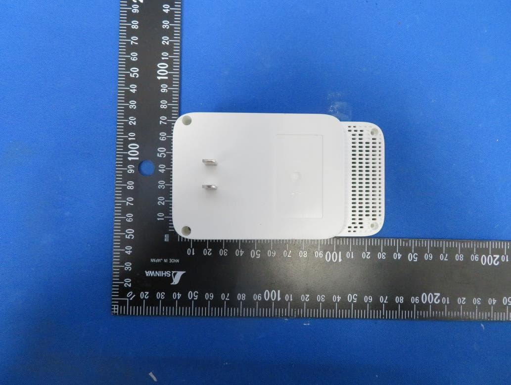
TE7RE230V2
Jan 13, 2021AC750 Wi-Fi Range Extender, AC1200 Wi-Fi Range Extender
Equipment Class
DTS - Digital Transmission System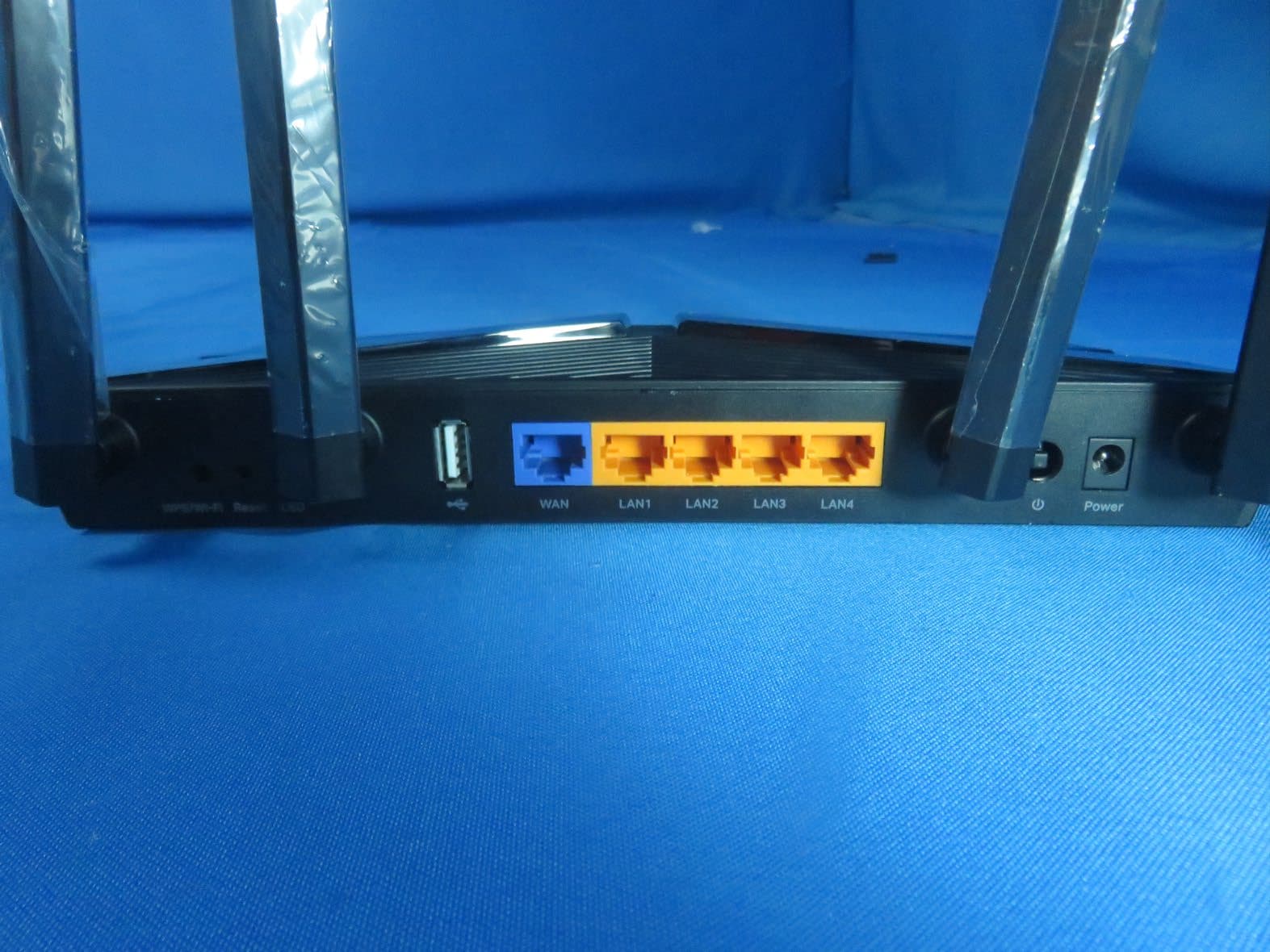
TE7AX20V2
Dec 22, 2020AX1800 Dual-Band Wi-Fi 6 Router
Equipment Class
DTS - Digital Transmission System
TE7EAP620HD
Dec 17, 2020AX1800 Wireless Dual-Band Gigabit Ceiling Mount Access Point
Equipment Class
NII - Unlicensed National Information Infrastructure TX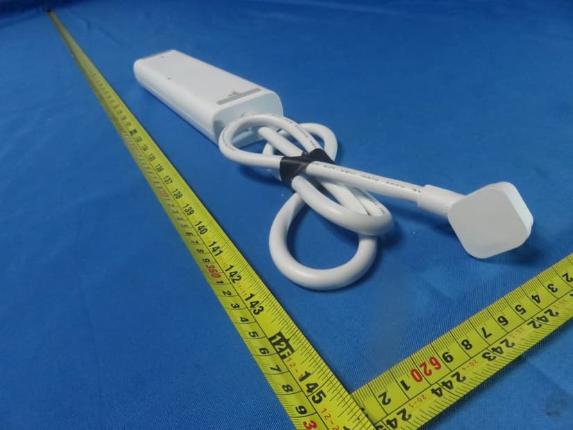
TE7KP303V2
Dec 15, 2020Kasa Smart Wi-Fi Power Strip, 3-Outlet
Equipment Class
DTS - Digital Transmission System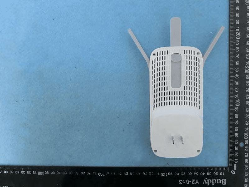
TE7RE550
Dec 03, 2020AC1750 Wi-Fi Range Extender, AC1900 MU-MIMO Wi-Fi Range Extender
Equipment Class
DTS - Digital Transmission System