TFB-MATRIXHPTransceiver Module
Laird Connectivity LLC
Click to zoom
Application Details
- Equipment Class
- DTS - Digital Transmission System
- Date of Grant
- Oct 21, 2007
- Application Purpose
- Original Equipment
- Date of Application
- Oct 18, 2007
- Equipment Note
- Transceiver Module
- Frequency Range
- 2405.00000000 - 2480.00000000
- Company
- Laird Connectivity LLC
- Country
- United States
Documents & Files
Document Text
Text extracted from the exhibit documents filed with the FCC. Open a document above to read the original.
Users Manual
LS Research, LLC. (Matrix/Zigbee Ready Module) Model #: MTX10 (10mW) and ZMXM-401-1-ES (100mW) 10mW Module 100mW Module Matrix Evaluation Kit and Application User's Guide 2 About This Manual This document provides the user with details in setting up and using the Matrix evaluation kits [Part#: MTX10-KIT1 (10mW) and MTX12-KIT1 (100mW)]. The document also provides information and references for software developers to write applications for use with the Matrix modules [Part#: MTX10 (10mW) and ZMXM-401-1-ES (100mW)]. This document contains the following chapters: Chapter 1 – Evaluation Kit Overview Chapter 2 – Quick Start Chapter 3 – Interface Module Description Chapter 4 – Matrix Evaluation Software Chapter 5 – Matrix/Zigbee Ready Module Input/Output Chapter 6 – Matrix Application Guide Appendix A – Open Field Range Test Results Appendix B – Agency Statements Related Documents Host Protocol EICD 3 Index CHAPTER 1......................................................................................................................................................... 4 MATRIX EVALUATION KIT OVERVIEW............................................................................................................... 4 CHAPTER 2......................................................................................................................................................... 5 QUICK START.................................................................................................................................................... 5 CHAPTER 3......................................................................................................................................................... 9 MATRIX INTERFACE MODULE........................................................................................................................... 9 CHAPTER 4....................................................................................................................................................... 15 SOFTWARE OVERVIEW................................................................................................................................... 15 CHAPTER 5....................................................................................................................................................... 33 MATRIX/ZIGBEE READY MODULE INPUT/OUTPUT......................................................................................... 33 CHAPTER 6....................................................................................................................................................... 35 MATRIX APPLICATION GUIDE.......................................................................................................................... 35 APPENDIX A..................................................................................................................................................... 47 RANGE TEST RESULTS................................................................................................................................... 47 APPENDIX B..................................................................................................................................................... 48 AGENCY STATEMENTS................................................................................................................................... 48 4 CHAPTER 1 Matrix Evaluation Kit Overview 1.1 Description The evaluation kit provides the end user the ability to quickly become familiar with the Matrix module. Included in the kit are two Matrix modules and a quick start guide to demonstrate the communication link between the two modules. Also included is a GUI interface referred to as the Matrix Evaluation Test Tool (TT) to quickly communicate with the RF modules. The Evaluation software demonstration is presented in Chapter 4. The important features provided by the evaluation software are: • Short and Long Addressing • Configurable Digital and Analog I/O • Demonstrating a Wireless Link • Packet Error Rate Statistics. 1.2 Contents The Matrix Evaluation Kit Contains: Two RF Modules with Firmware Loaded and Soldered to the Interface Modules Two Interface Modules Two RS-232 Interface Cables 4 AA Batteries 1 CD (includes User’s Guide, Host Protocol Document, EICD, and Matrix Evaluation Tool “Setup.exe” file) 5 CHAPTER 2 Quick Start 2.1 Board Description The Matrix module is a 2.4GHz 802.15.4 data transceiver module based on the Chipcon CC2430 Low Power 8051/Transceiver device. It provides enhanced range performance with either a 10mW or 100mW* power amplifier. The module also contains an integrated PCB trace antenna. Power is supplied by the host device through the interface connection in accordance to the operating voltage requirements with a nominal operating voltage of +3.3V. Exact details on the interface connections and messaging are available in the Matrix Electrical Interface Control Drawing. Figure 2-1. Top-Side of RF 10mW Matrix Module Figure 2-2. Top Side of Matrix 10mW Interface Board * Operation is Limited to 10mW Maximum for European Union Compliance 6 2.2 Operational Overview The quick start demonstration presented in this chapter is referred to as the ping pong test. The ping pong test allows an end user to easily verify communication between two transceivers and get a feel for the quality of the link via feedback of the flashing LEDs. Operation involves two boards, with one designated as a master device and the other as a slave device. The master periodically transmits packets to the slave. If the slave receives and verifies the packet, it will flash its LEDs and transmit an acknowledgement to the master. If the master receives and verifies the acknowledgement, it will flash its LEDs. In normal ping pong mode, LEDs indicate signal strength (two LEDs on indicate high signal strength, one LED indicates low signal strength). If the LEDs do not light, the pa…
Text truncated - open the document above for the full version.
Cover Letter(s)
Response to TCB Questions On Pg 20 of the report, second plot has a peak that exceeds the limit at 4.81GHz frequency. Corresponding radiated emissions data on Pg 15 shows a passing margin for this frequency. Please clarify why this level reduced when maximized for final readings. RESPONSE: The lower plot on page 20 shows a representative peak hold of TX harmonics using a 1 MHz RBW and a 10 kHz video bandwidth, in order to obtain reasonable sweep rates over the 5 to 18 GHz range. Final measurement of the harmonics is made with an average detector (10 hertz video bandwidth) which reduce the signal value by several dB. The signal being measured is continuously modulated during the compliance measurements. Pg 43 of the report refers to battery power and shows 3.9VDC operation. Modular approval request letter states 3.6VDC as the highest voltage it can operate at. Please clarify. RESPONSE: The test results presented on the module used specific test code that does not prevent operation outside the declared operating voltage range. The application code that is provided to the OEM user’s has this functionality included and it has been tested and verified.
Cover Letter(s)
August 24, 2007 Re: Modular Transmitter Approval FCC ID: TFB-MATRIXHP Gentlemen, The following information is being provided per the requirements of DA00-1407 regarding modular approval of Part 15 devices. This transceiver is a complete RF module with an integral reference oscillator. External connections are provided for power and data communication. The following numbered items correspond to similarly numbered paragraphs in DA00-1407. Each item is a response to the requirements of that document. 1) The module has integral RF shielding to isolate it from surrounding equipment and the larger environment in general. 2) All inputs are processed as data by the on-board microcontroller. The outside user has no direct control of transmit modulation. 3) There is a 1.8V voltage regulator that powers the radio circuits other than the power amplifier. The microcontroller monitors the amplifier power supply voltage on a continuous basis. Should the supply voltage be found to be greater than the specified maximum of 3.6 volts the unit will refuse to transmit. The minimum operating voltage is declared as 2.4 volts. 4) Either an integral PCB – trace antenna or a Nearson S131CL-5_RMM-2405S antenna with an MMCX connector is used with this module. This is in accordance with Part 15.203. 5) The module was tested in a stand-alone configuration and found to be compliant with Part 15 regulations. 6) An FCC ID label is affixed to each unit at the time of manufacture. Information is also clearly presented in the user guide about labeling requirements for the final assembly. 7) This unit is compliant with Part 15.247. Installation and other requirements are presented in the user guide to allow the unit to be correctly installed. 8) The unit is compliant with the RF exposure requirements of Parts 15.247, 15.1091, and 15.1093. Further information may be obtained from L.S. Research, LLC Sincerely, David Neperud W66 N220 Commerce Court, Cedarburg, Wisconsin 53012-2636 BUS 262.375.4400 FAX 262.375.4248 www.lsr.com
External Photos
Page 1 of 11 LS Research, LLC Matrix 100 mW FCC ID#: TFB-MATRIXHP Photo One – External Close up of FCC ID Label Page 2 of 11 LS Research, LLC Matrix 100 mW FCC ID#: TFB-MATRIXHP Photo Two – External Close up of FCC ID Label Page 3 of 11 LS Research, LLC Matrix 100 mW FCC ID#: TFB-MATRIXHP Photo Three – External View of Antenna Connector Page 4 of 11 LS Research, LLC Matrix 100 mW FCC ID#: TFB-MATRIXHP Photo Four – External Flip Side of Board Page 5 of 11 LS Research, LLC Matrix 100 mW FCC ID#: TFB-MATRIXHP Photo Five – External Close up of Antenna Connector Page 6 of 11 LS Research, LLC Matrix 100 mW FCC ID#: TFB-MATRIXHP Photo Six – External View Showing Antenna Connected Page 7 of 11 LS Research, LLC Matrix 100 mW FCC ID#: TFB-MATRIXHP Photo Seven – External Close up of Antenna Connected Page 8 of 11 LS Research, LLC Matrix 100 mW FCC ID#: TFB-MATRIXHP Photo Eight – External Front View Page 9 of 11 LS Research, LLC Matrix 100 mW FCC ID#: TFB-MATRIXHP Photo Nine – External Front View Page 10 of 11 LS Research, LLC Matrix 100 mW FCC ID#: TFB-MATRIXHP Photo Ten – External Showing Antenna Connector Page 11 of 11 LS Research, LLC Matrix 100 mW FCC ID#: TFB-MATRIXHP Photo Eleven – External Showing Antenna Connector
ID Label/Location Info
Page 1 of 11 LS Research, LLC Matrix 100 mW FCC ID#: TFB-MATRIXHP Photo One – External Close up of FCC ID Label
ID Label/Location Info
LS Research, LLC FCC ID Label File Matrix FCC ID: TFB-MATRIXHP 15mm x 15 mm Label Material: White Bond Paper Black Lettering Red Logo Label Size: 15mm x 15mm
Internal Photos
Page 1 of 6 LS Research, LLC Matrix 100 mW FCC ID#: TFB-MATRIXHP Photo One – Internal Open for Inspection, Partially Shielded Page 2 of 6 LS Research, LLC Matrix 100 mW FCC ID#: TFB-MATRIXHP Photo Two – Internal Open for Inspection, Partially Shielded Page 3 of 6 LS Research, LLC Matrix 100 mW FCC ID#: TFB-MATRIXHP Photo Three – Internal Complete Shield Removed, Showing Antenna Connected Page 4 of 6 LS Research, LLC Matrix 100 mW FCC ID#: TFB-MATRIXHP Photo Four – Internal Open for Inspection Page 5 of 6 LS Research, LLC Matrix 100 mW FCC ID#: TFB-MATRIXHP Photo Five – Internal Open for Inspection Page 6 of 6 LS Research, LLC Matrix 100 mW FCC ID#: TFB-MATRIXHP Photo Six – Internal Open for Inspection
RF Exposure Info
Prediction of MPE limit at a given distance Equation from page 18 of OET Bulletin 65, Edition 97-01 where:S = power density P = power input to the antenna G = power gain of the antenna in the direction of interest relative to an isotropic radiator R = distance to the center of radiation of the antenna Maximum peak output power at the antenna terminal: 19.36(dBm) Maximum peak output power at the antenna terminal:86.29785478(mW) Antenna gain(typical):2(dBi) Maximum antenna gain:1.584893192(numeric) Prediction distance: 20(cm) Prediction frequency:2450(MHz) MPE limit for uncontrolled exposure at prediction frequency:1(mW/cm^2) Power density at prediction frequency:0.027210(mW/cm^2) 2 4R PG S π =
Test Report
LS Research, LLC W66 N220 Commerce Court ● Cedarburg, WI 53012 ● USA Phone: 262.375.4400 ● Fax: 262.375.4248 www.lsr.com LS Research, LLC Prepared For: LS Research, LLC Template: 15.247 DTS TX (v2 9-06-06) Report #: 307340 TX Customer FCC ID #: TFB-MATRIXHP Page 1 of 48 ------------------------------------------------------------------------------------------------------------------------- ENGINEERING TEST REPORT # 307340 TX TCB Rev. 1 Compliance Testing of : Matrix 100mW Module Model # ZMXM-401-1-ES Test Date(s): June, July, August, 2007 Prepared For: LS Research, LLC Attn.: Mr. William Steinike W66 N220 Commerce Court Cedarburg, WI 53012 In accordance with: Federal Communications Commission (FCC) Part 15, Subpart C, Section 15.247 Digital Modulation Transmitters (DTS) Operating in the Frequency Band 2400 MHz – 2483.5 MHz This Test Report is issued under the Authority of: Brian Petted, VP of Engineering Signature: Date: September 10, 2007 Test Report Prepared by: Teresa A. White, Document Coordinator Signature: Date: September 10, 2007 Tested by: Kenneth Boston, PE EMC Lab Manager Signature: Date: September 10, 2007 This Test Report may not be reproduced, except in full, without written approval of LS Research, LLC. Prepared For: LS Research, LLC Model #: ZMXM-401-1-ES LS Research, LLC EUT: Matrix 100 mW Serial #: n/a Template: 15.247 DTS TX (V2 9-06-06) Report #: 307340 TX TCB Rev. 1 Customer FCC ID #:TFB-MATRIXHP Page 2 of 48 TABLE OF CONTENTS (PAGE 1 OF 2) EXHIBIT # SECTION # DESCRIPTION PAGE # 1 INTRODUCTION 4 1.1 Scope 4 1.2 Normative References 4 1.3 LS Research, LLC Test Facility 5 1.4 Location of Testing 5 1.5 Test Equipment Utilized 5 2 PERFORMANCE ASSESSMENT 6-8 2.1 Client Information 6 2.2 Equipment Under Test (EUT) Information 6 2.3 Associated Antenna Description 6 2.4 EUT’s Technical Specifications 7 2.5 Product Description 8 3 EUT OPERATING CONDITIONS & CONFIGURATIONS DURING TESTS 9 3.1 Climate Test Conditions 9 3.2 Applicability & Summary of EMC Emissions Test Results 9 3.3 Modifications Incorporated in the EUT for Compliance Purposes 9 3.4 Deviations and Exclusions from Test Specifications 9 4 DECLARATION OF CONFORMITY 10 5 RADIATED EMISSIONS TEST 11-21 5.1 Test Setup 11 5.2 Test Procedure 11 5.3 Test Equipment Utilized 12 5.4 Test Equipment List 12 5.5 Calculation of Radiated Emissions Limits 13 5.6 Radiated Emissions Data Chart 14-15 5.7 Test Setup Photo(s) – Radiated Emissions Test 16-17 5.8 Screen Captures – Radiated Emissions Testing 18-21 6 CONDUCTED EMISSIONS TEST, AC POWER LINE: 15.207 22-25 6.1 Test Setup 22 6.2 Test Procedure 22 6.3 Test Equipment List 22 6.4 FCC Limits of Conducted Emissions at the AC Mains Ports 23 6.5 Test Data Chart – Conducted Emission 24 6.6 Photo of Conducted Emissions Test 25 6.7 Screen Captures – Conducted Emissions 26 Prepared For: LS Research, LLC Model #: ZMXM-401-1-ES LS Research, LLC EUT: Matrix 100 mW Serial #: n/a Template: 15.247 DTS TX (V2 9-06-06) Report #: 307340 TX TCB Rev. 1 Customer FCC ID #:TFB-MATRIXHP Page 3 of 48 TABLE OF CONTENTS (PAGE 2 OF 2) EXHIBIT # SECTION # DESCRIPTION PAGE # 7 OCCUPIED BANDWIDTH: 15.247(A)(2) 27-31 7.1 Limits 27 7.2 Method of Measurements 27 7.3 Test Equipment List 27 7.4 Screen Captures – Occupied Bandwidth 28-31 8 BAND-EDGE MEASUREMENTS 32-33 8.1 Method of Measurements 32 8.2 Screen Captures – Band-Edge 32-33 9 POWER OUTPUT (CONDUCTED): 15.247(b) 34-36 9.1 Method of Measurements 34 9.2 Test Data 34 9.3 Test Equipment List 35 9.4 Screen Captures – Power Output (Conducted) 35-36 10 POWER SPECTRAL DENSITY: 15.247(e) 37-39 10.1 Limits 37 10.2 Test Equipment List 37 10.3 Test Data 37 10.4 Screen Captures – Power Spectral Density 38-39 11 SPURIOUS CONDUCTED EMISSIONS: 15.247(d) 40-43 11.1 Limits 40-41 11.2 Test Equipment List 41 11.3 Screen Captures – Spurious Conducted Emissions 42-43 12 FREQUENCY & POWER STABILITY OVER VOLTAGE VARIATIONS 44 13 CHANNEL PLAN AND SEPARATION 45 14 MPE CALCULATIONS 46 APPENDICES A TEST EQUIPMENT LIST 47 B JUSTIFICATIONS OF AVERAGE DUTY FACTOR CALCULATIONS 48 Prepared For: LS Research, LLC Model #: ZMXM-401-1-ES LS Research, LLC EUT: Matrix 100 mW Serial #: n/a Template: 15.247 DTS TX (V2 9-06-06) Report #: 307340 TX TCB Rev. 1 Customer FCC ID #:TFB-MATRIXHP Page 4 of 48 EXHIBIT 1. INTRODUCTION 1.1 SCOPE References: FCC Part 15, Subpart C, Section 15.247 Title: Telecommunication – Code of Federal Regulations, CFR 47, Part 15 Purpose of Test: To gain FCC Certification Authorization for Digital Modulation Transmitters operating in the Frequency Band of 2400 MHz – 2483.5 MHz Test Procedures: Both conducted and radiated emissions measurements were conducted in accordance with American National Standards Institute ANSI C63.4 – American National Standard for Methods of Measurement of Radio-Noise Emissions from Low-Voltage Electrical and Electronic Equipment in the Range of 9 kHz to 40 GHz. Environmental Classification: • Commercial, Industrial or Business • Residential 1.2 NORMATIVE REFERENCES Publication Year Title 47 CFR, Parts 0-15 (FCC) 2005 Code of Federal Regulations - Telecommunications ANSI C63.4 2004 American National Standard for Methods of Measurement of Radio-Noise Emissions from Low-Voltage Electrical and Electronic Equipment in the Range of 9 kHz to 40 GHz. CISPR 16-1-1 2003 Specification for radio disturbance and immunity measuring apparatus and methods. Part 1-1: Measuring Apparatus. CISPR 16-2-1 2003 Specification for radio disturbance and immunity measuring apparatus and methods. Part 201: Conducted disturbance measurement. FCC Public Notice DA 00-1407 2000 Part 15 Unlicensed Modular Transmitter Approval FCC ET Docket No. 99-231 2002 Amendment to FCC Part 15 of the Commission’s Rules Regarding Spread Spectrum Devices. FCC Procedures 2005, 03-23 Measurement of Digital Transmission Systems operating under Section 15.247. Prepared For: LS Research, LLC Model #: ZMXM-401-1-ES LS Research, LLC EUT: Matrix 100 mW Serial #: n/a Template: 15.247 DTS TX (V2 9-06-06…
Text truncated - open the document above for the full version.
Test Setup Photos
Test Setup Photos Company: LS Research, LLC FCC ID #: TFB-MATRIXHP Page 1 of 2 Test Setup Photo(s) – Radiated Emissions Test Vertical Orientation, EUT on Test Pedestal, F antenna Horizontal Orientation, EUT on Test Pedestal, F antenna Test Setup Photos Company: LS Research, LLC FCC ID #: TFB-MATRIXHP Page 2 of 2 Vertical Orientation, EUT on test pedestal, whip antenna Horizontal Orientation, EUT on test pedestal, whip antenna
Contact Information
Applicant
Brian Petted(Technology Leader)
Test Firm
LS Research, LLCRyan Urness
Technical Specifications
| # | Rule Parts | Frequency Range | Power Output |
|---|---|---|---|
| 1 | 15C | 2.40 GHz - 2.48 GHz | 86.30 mW |
Other Applications from Laird Connectivity LLC
TFB-1002
May 14, 2015SaBLE-x
Equipment Class
DTS - Digital Transmission System
TFB-1001
May 04, 2015TiWi-C-W Module
Equipment Class
DTS - Digital Transmission System
TFB-BT2
Sep 02, 2013TiWi-uB1
Equipment Class
DTS - Digital Transmission System
TFB-FREESTAR3
Dec 10, 2012FreeStar Tranceiver Module
Equipment Class
DTS - Digital Transmission System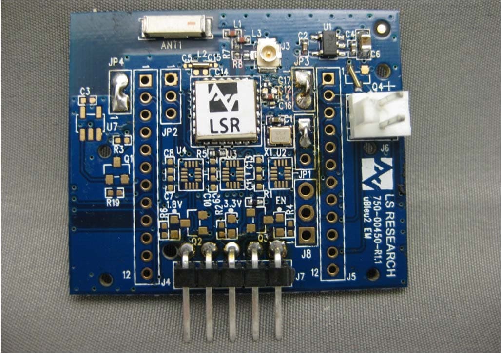
TFB-BT1
Nov 15, 2012TiWi-uB2 Bluetooth Module
Equipment Class
DTS - Digital Transmission System