TLZ-NM230NFIEEE 802.11 b/g/n Wireless LAN and Bluetooth combo M.2 1216 module
AzureWave Technologies, Inc.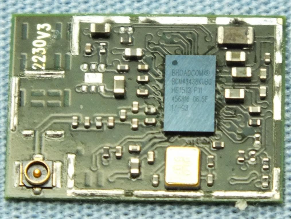
Click to zoom
Application Details
- Equipment Class
- DTS - Digital Transmission System
- Date of Grant
- Aug 09, 2015
- Application Purpose
- Original Equipment
- Date of Application
- Aug 06, 2015
- Equipment Note
- IEEE 802.11 b/g/n Wireless LAN and Bluetooth combo M.2 1216 module
- Frequency Range
- 2402.00000000 - 2480.00000000
- Company
- AzureWave Technologies, Inc.
- Country
- Taiwan
Documents & Files
Document Text
Text extracted from the exhibit documents filed with the FCC. Open a document above to read the original.
Users Manual
- 1 - AW-NM230NF-H IEEE 802.11 b/g/n Wireless LAN and Bluetooth Combo M.2 1216 Module User Guide Document release Date Modification Initials Approved Version 0.1 2015/03/10 Initial Version Chao Lee Amos Fu Version 0.2 2015/8/3 Add pin definition , pin map Chao Lee Amos Fu 1. WLAN Basic Test Driver Installation Throughput Test RF Tx/Rx Performance Test 2. Bluetooth Basic Test Download Mini-driver Throughput Test RF Performance Test 3. Statement 4. Pin definition/Pin map - 2 - 1. WLAN Basic Test **Must connect USB to PC Driver Installation DRIVER INSTALLATION (IN LINUX) •First prepare the Broadcom’s linux package, and put it in the “home”folder. •Open the Terminal, enter the command: sudo su and password. •Enter cd /home/username/drivername/src/dhd/linux •Enter make dhd-cdc-sdmmc-gpl to generate the dhd.ko file in /home/username/ drivername /src/dhd/linux/dhd-cdc-sdmmc-gpl-kernelversion •Enter Insmod /(path of dhd.ko file) firmware_path=/(path of firmware file) nvram_path=/(path of nvram file) to enable. •Enter rmmod dhd to disable Throughput Test CONNECTING TO WIRELESS NETWORKS The examples in the following sections illustrate how to connect to both infrastructure and ad hoc networks, including infrastructure networks that use no security, WEP security, and WPA/PSK and WPS2/PSK security. SCANNING FOR WIRELESS NETWORKS To force the dongle to scan • Run wl scan. To force the dongle to return the results of the scan • Run wl scanresults. Example results returned when an AP is found: • SSID: “Eval4325” • Mode: Managed: RSSI: -48 dBm noise: -105 dBm Channel: 1 • BSSID: 00:10:18:90:2E:C1 Capability: ESS ShortSlot • Supported Rates: [ 1(b) 2(b) 5.5(b) 11(b) 18 24 36 54 6 9 12 48 ] Example results returned when an ad hoc network is found: • SSID: “ADHOC#1” • Mode: Ad Hoc RSSI: -41 dBm noise: -105 dBm Channel: 1 - 3 - • BSSID: B2:51:28:6B:3C:A1 Capability: IBSS • Supported Rates: [ 1(b) 2(b) 5.5(b) 11(b) ] CONNECTING TO AN INFRASTRUCTURE NETWORK WITH NO SECURITY (AP CONNECTION) To connect to the network through an AP with SSID = Eval4325 Run wl join Eval4325. CONNECTING TO AN INFRASTRUCTURE NETWORK WITH WEP SECURITY To connect to the network that uses 12345 as the network key • Run wl join Eval4325 key 12345. CONNECTING TO AN INFRASTRUCTURE NETWORK WITH WPA-PSK/WPA2-PSK SECURITY To specify TKIP or AES as the data encryption method • Run wl wsec 3/7. To enable the supplicant • Run wl sup_wpa 1. To specify the PSK passphrase (network key) to use • Run wl set_psk $passphrase. To connect to a network that uses WPA-PSK security • Run wl join Eval4325 imode bss amode wpapsk. To connect to a network that uses WPA2-PSK security • Run wl join Eval4325 imode bss amode wpa2psk. CONNECTING TO AN AD HOC NETWORK USING CHANNEL 1 To set the channel to channel 1 • Run wl channel 1. To connect to the ad hoc network with SSID = 4325-ADHOC • Run wl join 4325-ADHOC imode ibss. MANAGING POWER CONSUMPTION To disable Power Save (PS) mode (default) • Run wl PM 0. To enable legacy IEEE 802.11 Power Save (PS) mode • Run wl PM 1. To enable Fast IEEE 802.11 Power Save mode • Run wl PM 2. - 4 - Note: • The STA automatically transitions to Legacy PS mode when no data is being sent or received. • The STA automatically disables PS mode when data is being sent or received. MEASURING WLAN THROUGHPUT The throughput measurement shows the performance of the TCP/IP layer over the wireless link. To achieve the best results, run the measurement test in a clean environment with as little interference as possible . The test can be run with the adapter connected to either an Infrastructure network (see Fig. 2.2) or an ad hoc network (see Fig. 2.3). An AP that is known to be in good working order should be used for the infrastructure mode test. MEASURING THROUGHPUT USING NETIQ CHARIOT Test Procedure 1. Bring up the AW-NM230NF-H demo boar with the IP address set as 192.168.1.110. 2. Connect the reference computer with Chariot Console, which is assigned an IP address of 192.168.1.100, to the LAN HOST COMPUTER. AW-NM230NF-H EndPoint Reference Computer Chariot Console HOST COMPUTER. AW-NM230NF -H EndPoint A P LAN Port Reference Computer Chariot Console FIG. 2.2 FIG. 2.3 - 5 - port of the AP 3. Verify that communication exists between the reference computer and the AW-NM230NF-H demo board by pinging 192.168.1.100 from the AW-NM230NF-H host console. 4. Set up Chariot. a. On the host computer, activate EndPoint: b. Using Chariot Console on the reference computer, create two pair groups (192.168.1.100 and 192.168.1.110) using the Chariot Throughput.scr script. Run the throughput test for a specified period of time and observe the results. RF Tx/Rx Performance Test CREATING A Tx TEST (In Ubuntu linux 12.04) 1. Open the Terminal, enter the command: sudo su and password. 2. Enter Insmod /(path of dhd.ko file) firmware_path=/(path of firmware file) nvram_path=/(path of nvram file) to enable. 3. Enter the wl ver command to check the current WL driver version. 4. Run the following command set (delay at least 700ms between each command): 11b rate: ./wl mpc 0 ./wl country ALL ./wl up ./wl scansuppress 1 ./wl band b ./wl channel 7 ./wl nrate -r 11 ./wl txpwr1 -o -q 68 ./wl phy_forcecal 1 ./wl pkteng_start 00:11:22:33:44:55 tx 300 1500 0 This will send continuous Tx Packets with 300 us packet interval,1500 byte packet length. Data rate =11Mbps ,Channel=7 and output power =17dBm(68/4=17 q means quarter). - 6 - 11g rate: ./wl mpc 0 ./wl country ALL ./wl up ./wl scansuppress 1 ./wl band b ./wl channel 7 ./wl nrate -r 54 ./wl txpwr1 -o -q 60 ./wl phy_forcecal 1 ./wl pkteng_start 00:11:22:33:44:55 tx 300 1500 0 This will send continuous Tx Packets with 300 us packet interval,1500 byte packet length. Data rate =54Mbps ,Channel=7 and output power =15dBm(60/4=15 q means quarter). 2.4G 11n 20 SISO rate: ./wl mpc 0 ./wl country ALL ./wl up ./wl scansuppress 1 ./wl band b ./wl channel 7 ./wl nrate -m 7 ./wl chanspec -c 7 -b 2 -w 20 -s 0 ./wl txpwr1 -o -q 52 ./wl phy_for…
Text truncated - open the document above for the full version.
Users Manual
- 1 - AW-NM230NF IEEE 802.11 b/g/n Wireless LAN and Bluetooth Combo M.2 1216 Module User Guide Document release Date Modification Initials Approved Version 0.1 2015/03/10 Initial Version Chao Lee Amos Fu Version 0.2 2015/8/3 Add Pin definition / pin map Chao Lee Amos Fu 1. WLAN Basic Test Driver Installation Throughput Test RF Tx/Rx Performance Test 2. Bluetooth Basic Test Download Mini-driver Throughput Test RF Performance Test 3. Statement 4. Pin definition / pin map - 2 - 1. WLAN Basic Test **Must connect USB to PC Driver Installation DRIVER INSTALLATION (IN LINUX) •First prepare the Broadcom’s linux package, and put it in the “home”folder. •Open the Terminal, enter the command: sudo su and password. •Enter cd /home/username/drivername/src/dhd/linux •Enter make dhd-cdc-sdmmc-gpl to generate the dhd.ko file in /home/username/ drivername /src/dhd/linux/dhd-cdc-sdmmc-gpl-kernelversion •Enter Insmod /(path of dhd.ko file) firmware_path=/(path of firmware file) nvram_path=/(path of nvram file) to enable. •Enter rmmod dhd to disable Throughput Test CONNECTING TO WIRELESS NETWORKS The examples in the following sections illustrate how to connect to both infrastructure and ad hoc networks, including infrastructure networks that use no security, WEP security, and WPA/PSK and WPS2/PSK security. SCANNING FOR WIRELESS NETWORKS To force the dongle to scan • Run wl scan. To force the dongle to return the results of the scan • Run wl scanresults. Example results returned when an AP is found: • SSID: “Eval4325” • Mode: Managed: RSSI: -48 dBm noise: -105 dBm Channel: 1 • BSSID: 00:10:18:90:2E:C1 Capability: ESS ShortSlot • Supported Rates: [ 1(b) 2(b) 5.5(b) 11(b) 18 24 36 54 6 9 12 48 ] Example results returned when an ad hoc network is found: • SSID: “ADHOC#1” • Mode: Ad Hoc RSSI: -41 dBm noise: -105 dBm Channel: 1 - 3 - • BSSID: B2:51:28:6B:3C:A1 Capability: IBSS • Supported Rates: [ 1(b) 2(b) 5.5(b) 11(b) ] CONNECTING TO AN INFRASTRUCTURE NETWORK WITH NO SECURITY (AP CONNECTION) To connect to the network through an AP with SSID = Eval4325 Run wl join Eval4325. CONNECTING TO AN INFRASTRUCTURE NETWORK WITH WEP SECURITY To connect to the network that uses 12345 as the network key • Run wl join Eval4325 key 12345. CONNECTING TO AN INFRASTRUCTURE NETWORK WITH WPA-PSK/WPA2-PSK SECURITY To specify TKIP or AES as the data encryption method • Run wl wsec 3/7. To enable the supplicant • Run wl sup_wpa 1. To specify the PSK passphrase (network key) to use • Run wl set_psk $passphrase. To connect to a network that uses WPA-PSK security • Run wl join Eval4325 imode bss amode wpapsk. To connect to a network that uses WPA2-PSK security • Run wl join Eval4325 imode bss amode wpa2psk. CONNECTING TO AN AD HOC NETWORK USING CHANNEL 1 To set the channel to channel 1 • Run wl channel 1. To connect to the ad hoc network with SSID = 4325-ADHOC • Run wl join 4325-ADHOC imode ibss. MANAGING POWER CONSUMPTION To disable Power Save (PS) mode (default) • Run wl PM 0. To enable legacy IEEE 802.11 Power Save (PS) mode • Run wl PM 1. To enable Fast IEEE 802.11 Power Save mode • Run wl PM 2. - 4 - Note: • The STA automatically transitions to Legacy PS mode when no data is being sent or received. • The STA automatically disables PS mode when data is being sent or received. MEASURING WLAN THROUGHPUT The throughput measurement shows the performance of the TCP/IP layer over the wireless link. To achieve the best results, run the measurement test in a clean environment with as little interference as possible . The test can be run with the adapter connected to either an Infrastructure network (see Fig. 2.2) or an ad hoc network (see Fig. 2.3). An AP that is known to be in good working order should be used for the infrastructure mode test. MEASURING THROUGHPUT USING NETIQ CHARIOT Test Procedure 1. Bring up the AW-NM230NF demo boar with the IP address set as 192.168.1.110. 2. Connect the reference computer with Chariot Console, which is assigned an IP address of 192.168.1.100, to the LAN HOST COMPUTER. AW-NM230NF EndPoint Reference Computer Chariot Console HOST COMPUTER. AW-NM230NF EndPoint A P LAN Port Reference Computer Chariot Console FIG. 2.2 FIG. 2.3 - 5 - port of the AP 3. Verify that communication exists between the reference computer and the AW-NM230NF demo board by pinging 192.168.1.100 from the AW-NM230NF host console. 4. Set up Chariot. a. On the host computer, activate EndPoint: b. Using Chariot Console on the reference computer, create two pair groups (192.168.1.100 and 192.168.1.110) using the Chariot Throughput.scr script. Run the throughput test for a specified period of time and observe the results. RF Tx/Rx Performance Test CREATING A Tx TEST (In Ubuntu linux 12.04) 1. Open the Terminal, enter the command: sudo su and password. 2. Enter Insmod /(path of dhd.ko file) firmware_path=/(path of firmware file) nvram_path=/(path of nvram file) to enable. 3. Enter the wl ver command to check the current WL driver version. 4. Run the following command set (delay at least 700ms between each command): 11b rate: ./wl mpc 0 ./wl country ALL ./wl up ./wl scansuppress 1 ./wl band b ./wl channel 7 ./wl nrate -r 11 ./wl txpwr1 -o -q 68 ./wl phy_forcecal 1 ./wl pkteng_start 00:11:22:33:44:55 tx 300 1500 0 This will send continuous Tx Packets with 300 us packet interval,1500 byte packet length. Data rate =11Mbps ,Channel=7 and output power =17dBm(68/4=17 q means quarter). - 6 - 11g rate: ./wl mpc 0 ./wl country ALL ./wl up ./wl scansuppress 1 ./wl band b ./wl channel 7 ./wl nrate -r 54 ./wl txpwr1 -o -q 60 ./wl phy_forcecal 1 ./wl pkteng_start 00:11:22:33:44:55 tx 300 1500 0 This will send continuous Tx Packets with 300 us packet interval,1500 byte packet length. Data rate =54Mbps ,Channel=7 and output power =15dBm(60/4=15 q means quarter). 2.4G 11n 20 SISO rate: ./wl mpc 0 ./wl country ALL ./wl up ./wl scansuppress 1 ./wl band b ./wl channel 7 ./wl nrate -m 7 ./wl chanspec -c 7 -b 2 -w 20 -s 0 ./wl txpwr1 -o -q 52 ./wl phy_forcecal 1 ./w…
Text truncated - open the document above for the full version.
Cover Letter(s)
Confidentiality Request Letter Date: 2015/7/24 Federal Communications Commission Authorization and Evaluation Division FCC ID:TLZ-NM230NF Permanent Confidentiality Request Pursuant to Sections 0.457 and 0.459 of the Commission’s Rules, the Applicant Hereby requests confidential treatment of information accompanying this Application As outlined below: 1. Block Diagram 2. Circuit Diagram 3. Operational Description The above materials contain trade secrets and proprietary information not customarily released to the public. The public disclosure of these matters might be harmful to the Applicant and provide unjustified benefits to its competitors. The Applicant understands that pursuant to Rule 0.457, disclosure of this Application and all accompanying documentation will not be made before the date of the Grant for this application Sincerely, Applicant’s company name : AzureWave Technologies, Inc. Applicant’s company address : 8F, No. 94, Baozhong Rd., Xindian, Taiwan 231 Signature : Job Title and Dept. : Ivan Chen / Manager E-mail : [email protected] Tel. : 02-55995805
Cover Letter(s)
AzureWave Technologies, Inc. 8 F., No. 94, Baozhong Rd., Xindian,Taipei, Taiwan 231 TEL:886-2-66289888 FAX:886-2-66289666 Date: July 24, 2015 Subject: Ad Hoc Mode Function Declaration FCC ID: TLZ-NM230NF IC ID: 6100A-NM230NF To Whom it may concern, We, AzureWave Technologies, Inc. declare that the device does not support any non-US channels and country code selection in all the operational mode(s) for the following product. Regards, Applicant : AzureWave Technologies, Inc. Address : 8 F., No. 94, Baozhong Rd., Xindian,Taiwan 231 Signature : Name and Job Title. : Ivan Chen / Manager E-mail [email protected] Tel. 02-55995599
Cover Letter(s)
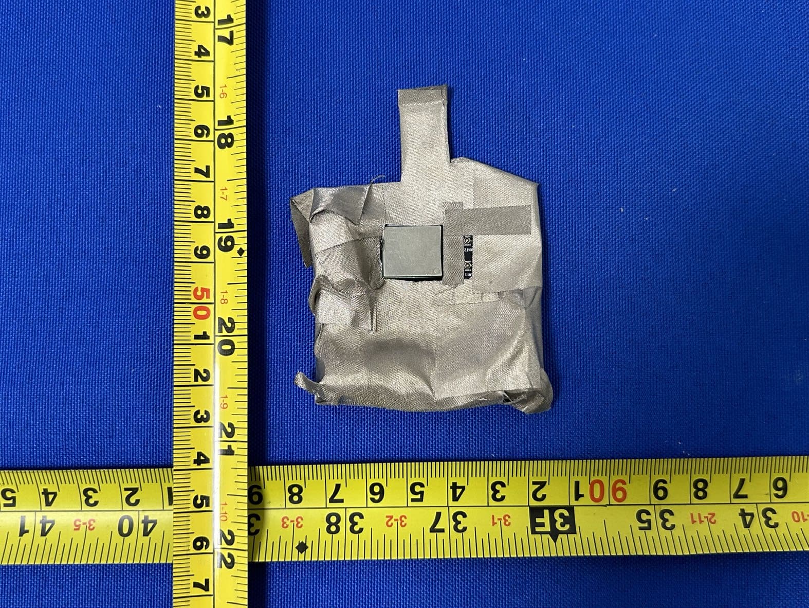
RF_734_00, Issue 1 Modular Approval Request FCC (per DA 00-1407) FCC ID: TLZ-NM230NF Items to be covered Answer from applicant 1. The modular transmitter must have its own RF shielding. The modular has a shielding Case. Please refer to EUT Photo. 2. The modular transmitter must have buffered modulation/data inputs (if such inputs are provided) to ensure that the module will comply with Part 15 requirements under conditions of excessive data rates or over-modulation. The component number is For both modes BCM43438KUBG 3. The modular transmitter must have its own power supply regulation. The component number is For AW-NM230NF-H BCM43438KUBG For AW-NM230NF BCM43438KUBG / RE0108ADD6-18 4. The modular transmitter must comply with the antenna requirements of Section 15.203 and 15.204(c). The antenna must either be permanently attached or employ a “unique” antenna coupler (at all connections between the module and the antenna, including the cable).. IPEX connector is used. And no external amplifier will be used with this modular. 5. The modular transmitter must be tested in a stand-alone configuration, i.e., the module must not be inside another device during testing. This is intended to demonstrate that the module is capable of complying with Part 15 emission limits regardless of the device into which it is eventually installed. This modular is tested under stand-alone configuration. Please refer to Test setup photo. 6. The modular transmitter must be labeled with its own FCC ID number, and, if the FCC ID is not visible when the module is installed inside another device, then the outside of the device into which the module is installed must also display a label referring to the enclosed module. This exterior label can use wording such as the following: “Contains Transmitter Module FCC ID: XYZMODEL1” or “Contains FCC ID: XYZMODEL1.” Any similar wording that expresses the same meaning may be used. The Grantee may either provide such a label, an example of which must be included in the application for equipment authorization, or, must provide adequate instructions along with the module which explain this requirement. In the latter case, a copy of these instructions must be included in the application for equipment authorization. The modular transmitter is labeled with its own FCC ID number. Please refer to label sample and label location. 7. The modular transmitter must comply with any specific rule or operating requirements applicable to the transmitter and the manufacturer must provide adequate instructions along with the module to explain any such requirements. A copy of these instructions must be included in the application for equipment authorization. For example, there are very strict operational and timing requirements that must be met before a transmitter is authorized for operation under Section 15.231. For instance, data transmission is prohibited, except for operation under Section 15.231(e), in which case there are separate field strength level and timing requirements. Compliance with these requirements must be assured. The modular complies with this requirement. Please refer to user manual. 8. The modular transmitter must comply with any applicable RF exposure requirements. For example, FCC Rules in Sections 2.1091, 2.1093 and specific Sections of Part 15, including 15.319(i), 15.407(f), 15.253(f) and 15.255(g), require that Unlicensed PCS, UNII and millimeter wave devices perform routine environmental evaluation for RF Exposure to demonstrate compliance. In addition, spread spectrum transmitters operating under Section 15.247 are required to address RF Exposure compliance in accordance with Section 15.247(b)(4). Modular transmitters approved under other Sections of Part 15, when necessary, may also need to address certain RF Exposure concerns, typically by providing specific installation and operating instructions for users, installers and other interested parties to ensure compliance. The device complies with this requirement. Please refer to RF exposure report. Note: If compliance with one or more of the numbered requirements, listed above, cannot be demonstrated, it may be possible to obtain a “Limited Modular Approval” (LMA). Name and surname of applicant (or authorized representative): __________________ RF_734_00, Issue 1 Date: ___04 August 2015____ Signature: ___________________________
ID Label/Location Info
Label drawing Label location
Internal Photos
Project No.: 550703 Page No. : 5 of 7 Model: AW-NM230NF-H Project No.: 550703 Page No. : 6 of 7 Model: AW-NM230NF Project No.: 550703 Page No. : 7 of 7
RF Exposure Info
Report No.: FA550703 Page : 1 of 5 Report Version: Rev. 01 FCC RF Exposure Report FCC ID : TLZ-NM230NF Equipment : IEEE 802.11 b/g/n WLAN and Bluetooth combo module Model No. : AW-NM230NF、AW-NM230NF-H (Please refer to section 1.1.1 for more details.) Brand Name : AzureWave Applicant : AzureWave Technologies, Inc. Address : 8 F., No. 94, Baozhong Rd., Xindian,Taipei, Taiwan 231 Standard : 47 CFR FCC Part 2.1091 Received Date : May 07, 2015 Tested Date : Jul. 03 ~ Jul. 20, 2015 We, International Certification Corp., would like to declare that the tested sample has been evaluated and in compliance with the requirement of the above standards. The test results contained in this report refer exclusively to the product. It may be duplicated completely for legal use with the approval of the applicant. It shall not be reproduced except in full without the written approval of our laboratory. Approved & Reviewed by: Gary Chang / Manager Ty: XXX Report No.: FA550703 Page : 2 of 5 Report Version: Rev. 01 Table of Contents 1 MPE EVALUATION OF MOBILE DEVICES ......................................................................................... 4 1.1 LIMITS FOR GENERAL POPULATION/UNCONTROLLED EXPOSURE............................................. 4 1.2 MPE EVALUATION FORMULA ............................................................................................................. 4 1.3 MPE EVALUATION RESULTS .............................................................................................................. 4 2 TEST LABORATORY INFORMATION ................................................................................................. 5 Report No.: FA550703 Page : 3 of 5 Report Version: Rev. 01 Release Record Report No. Version Description Issued Date FA550703 Rev. 01 Initial issue Jul. 30, 2015 Report No.: FA550703 Page : 4 of 5 Report Version: Rev. 01 1 MPE EVALUATION OF MOBILE DEVICES Human exposure to RF emissions from mobile devices (47 CFR §2.1091) may be evaluated based on the MPE limits adopted by the FCC for electric and magnetic field strength and/or power density, as appropriate, since exposures are assumed to occur at distances of 20 cm or more from persons. 1.1 LIMITS FOR GENERAL POPULATION/UNCONTROLLED EXPOSURE Frequency Range (MHz) Power Density (mW /cm 2 ) Averaging Time (minutes) 300~1500 F/1500 30 1500~100000 1.0 30 1.2 MPE EVALUATION FORMULA Pd = 2 **4RPi Pt Where Pd= Power density in mW/cm 2 Pt= EIRP in Mw Pi= 3.1416 R= Measurement distance 1.3 MPE EVALUATION RESULTS Modulation Mode Frequency Range (MHz) Maximum Conducted Power (dBm) Antenna Gain (dBi) Distance (cm) Power Density (mW/cm 2 ) Limit (mW/cm 2 ) WLAN 2412~2462 21.89 3 20 0.061 1 BT EDR 2402~2480 8.19 3 20 0.003 1 BT LE 2402~2480 6.49 3 20 0.002 1 Report No.: FA550703 Page : 5 of 5 Report Version: Rev. 01 2 Test laboratory information Established in 2012, ICC provides foremost EMC & RF Testing and advisory consultation services by our skilled engineers and technicians. Our services employ a wide variety of advanced edge test equipment and one of the widest certification extents in the business. International Certification Corp, it is our definitive objective is to institute long term, trust-based associations with our clients. The expectation we set up with our clients is based on outstanding service, practical expertise and devotion to a certified value structure. Our passion is to grant our clients with best EMC / RF services by oriented knowledgeable and accommodating staff. Our Test sites are located at Linkou District and Kwei Shan Hsiang. Location map can be found on our website http://www.icertifi.com.tw. Linkou Kwei Shan Kwei Shan Site II Tel: 886-2-2601-1640 Tel: 886-3-271-8666 Tel: 886-3-271-8640 No. 30-2, Ding Fwu Tsuen, Lin Kou District, New Taipei City, Taiwan, R.O.C. No. 3-1, Lane 6, Wen San 3rd St., Kwei Shan Hsiang, Tao Yuan Hsien 333, Taiwan, R.O.C. No. 14-1, Lane 19, Wen San 3rd St., Kwei Shan Hsiang, Tao Yuan Hsien 333, Taiwan, R.O.C. If you have any suggestion, please feel free to contact us as below information Tel: 886-3-271-8666 Fax: 886-3-318-0155 Email: [email protected] ══END══
Test Report
Report No.: FR550703AE Page : 1 of 37 Report Version: Rev. 01 FCC Test Report FCC ID : TLZ-NM230NF Equipment : IEEE 802.11 b/g/n Wireless LAN and Bluetooth combo M.2 1216 module Model No. : AW-NM230NF、AW-NM230NF-H (Please refer to section 1.1.1 for more details.) Brand Name : AzureWave Applicant : AzureWave Technologies, Inc. Address : 8 F., No. 94, Baozhong Rd., Xindian,Taipei, Taiwan 231 Standard : 47 CFR FCC Part 15.247 Received Date : May 07, 2015 Tested Date : Jul. 03 ~ Jul. 20, 2015 We, International Certification Corp., would like to declare that the tested sample has been evaluated and in compliance with the requirement of the above standards. The test results contained in this report refer exclusively to the product. It may be duplicated completely for legal use with the approval of the applicant. It shall not be reproduced except in full without the written approval of our laboratory. Approved & Reviewed by: Gary Chang / Manager Ty: XXX Report No.: FR550703AE Page : 2 of 37 Report Version: Rev. 01 Table of Contents 1 GENERAL DESCRIPTION .................................................................................................................... 5 1.1 Information .............................................................................................................................................. 5 1.2 Local Support Equipment List ................................................................................................................ 7 1.3 Test Setup Chart .................................................................................................................................... 7 1.4 Test Equipment List and Calibration Data .............................................................................................. 8 1.5 Test Standards ....................................................................................................................................... 9 1.6 Measurement Uncertainty ...................................................................................................................... 9 2 TEST CONFIGURATION ..................................................................................................................... 10 2.1 Testing Condition ................................................................................................................................. 10 2.2 The Worst Test Modes and Channel Details ....................................................................................... 10 3 TRANSMITTER TEST RESULTS ........................................................................................................ 11 3.1 Conducted Emissions ........................................................................................................................... 11 3.2 6dB and Occupied Bandwidth .............................................................................................................. 16 3.3 RF Output Power .................................................................................................................................. 18 3.4 Power Spectral Density ........................................................................................................................ 20 3.5 Emissions in Restricted Frequency Bands ........................................................................................... 22 3.6 Emissions in non-restricted Frequency Bands ..................................................................................... 34 4 TEST LABORATORY INFORMATION ............................................................................................... 37 Report No.: FR550703AE Page : 3 of 37 Report Version: Rev. 01 Release Record Report No. Version Description Issued Date FR550703AE Rev. 01 Initial issue Jul. 30, 2015 Report No.: FR550703AE Page : 4 of 37 Report Version: Rev. 01 Summary of Test Results FCC Rules Test Items Measured Result 15.207 AC Power Line Conducted Emissions [dBuV]: 0.474MHz 29.77 (Margin -16.68dB) - AV Pass 15.247(d) 15.209 Radiated Emissions [dBuV/m at 3m]: 4960.00MHz 52.95 (Margin -1.05dB) - AV Pass 15.247(b)(3) Maximum Output Power Power [dBm]: 6.63 Pass 15.247(a)(2) 6dB Bandwidth Meet the requirement of limit Pass 15.247(e) Power Spectral Density Meet the requirement of limit Pass 15.203 Antenna Requirement Meet the requirement of limit Pass Report No.: FR550703AE Page : 5 of 37 Report Version: Rev. 01 1 General Description 1.1 Information 1.1.1 Product Details The following models are provided to this EUT. Brand Name Model Name Product Name Description AzureWave AW-NM230NF IEEE 802.11 b/g/n Wireless LAN and Bluetooth combo M.2 1216 module 1.8Vdc with LDO AW-NM230NF-H 3.3Vdc w/o LDO Note: RF portion is identical to each model. 1.1.2 Specification of the Equipment under Test (EUT) RF General Information Frequency Range (MHz) Bluetooth Mode Ch. Freq. (MHz) Channel Number Data Rate 2400-2483.5 V4.1 LE 2402-2480 0-39 [40] 1 Mbps Note 1: Bluetooth LE (Low energy) uses GFSK modulation. 1.1.3 Antenna Details Ant. No. Brand Model Type Connector Gain (dBi) 1 Walsin RFMTA340715IMLB301 PIFA I-PEX 3 1.1.4 Power Supply Type of Equipment under Test (EUT) Power Supply Type Model AW-NM230NF: 1.8Vdc Model AW-NM230NF-H: 3.3Vdc 1.1.5 Accessories N/A Report No.: FR550703AE Page : 6 of 37 Report Version: Rev. 01 1.1.6 Channel List Frequency band (MHz) 2400~2483.5 Channel Frequency (MHz) Channel Frequency (MHz) Channel Frequency (MHz) Channel Frequency (MHz) 37 2402 9 2422 18 2442 28 2462 0 2404 10 2424 19 2444 29 2464 1 2406 38 2426 20 2446 30 2466 2 2408 11 2428 21 2448 31 2468 3 2410 12 2430 22 2450 32 2470 4 2412 13 2432 23 2452 33 2472 5 2414 14 2434 24 2454 34 2474 6 2416 15 2436 25 2456 35 2476 7 2418 16 2438 26 2458 36 2478 8 2420 17 2440 27 2460 39 2480 1.1.7 Test Tool and Duty Cycle Test tool Blue Tool, Version 1.9.0.2 Duty cycle of test signal (%) 67.28% Duty Factor (dB) 1.72 1.1.8 Power Setting Modulation Mode Test Frequency…
Text truncated - open the document above for the full version.
Test Report
Report No.: FR550703AC Page : 1 of 57 Report Version: Rev. 01 FCC Test Report FCC ID : TLZ-NM230NF Equipment : IEEE 802.11 b/g/n Wireless LAN and Bluetooth combo M.2 1216 module Model No. : AW-NM230NF、AW-NM230NF-H (Please refer to section 1.1.1 for more details.) Brand Name : AzureWave Applicant : AzureWave Technologies, Inc. Address : 8 F., No. 94, Baozhong Rd., Xindian,Taipei, Taiwan 231 Standard : 47 CFR FCC Part 15.247 Received Date : May 07, 2015 Tested Date : Jul. 03 ~ Jul. 20, 2015 We, International Certification Corp., would like to declare that the tested sample has been evaluated and in compliance with the requirement of the above standards. The test results contained in this report refer exclusively to the product. It may be duplicated completely for legal use with the approval of the applicant. It shall not be reproduced except in full without the written approval of our laboratory. Approved & Reviewed by: Gary Chang / Manager Ty: XXX Report No.: FR550703AC Page : 2 of 57 Report Version: Rev. 01 Table of Contents 1 GENERAL DESCRIPTION .................................................................................................................... 5 1.1 Information .............................................................................................................................................. 5 1.2 Local Support Equipment List ................................................................................................................ 7 1.3 Test Setup Chart .....................................…
Text truncated - open the document above for the full version.
Contact Information
Applicant
Patrick Lin(Director)
Technical Contact
International Certification Corp.Gary Chang
[email protected]886-3-271-8628
No.3-1, Lane 6, Wen San 3rd St. Kwei Shan · Taiwan
Non-Technical Contact
International Certification Corp.Wendy Liao
[email protected]886-3-271-8629
Test Firm
International Certification Corp.Fu-Cheng Chuang
Technical Specifications
| # | Rule Parts | Frequency Range | Power Output |
|---|---|---|---|
| 2 | 15C | 2.40 GHz - 2.48 GHz | 5.00 mW |
Other Applications from AzureWave Technologies, Inc.
TLZ-XM643SUR
Jul 22, 2026IEEE 802.11 a/b/g/n/ac/ax Wi-Fi +Bluetooth 6.0 Combo LGA Module
Equipment Class
NII - Unlicensed National Information Infrastructure TX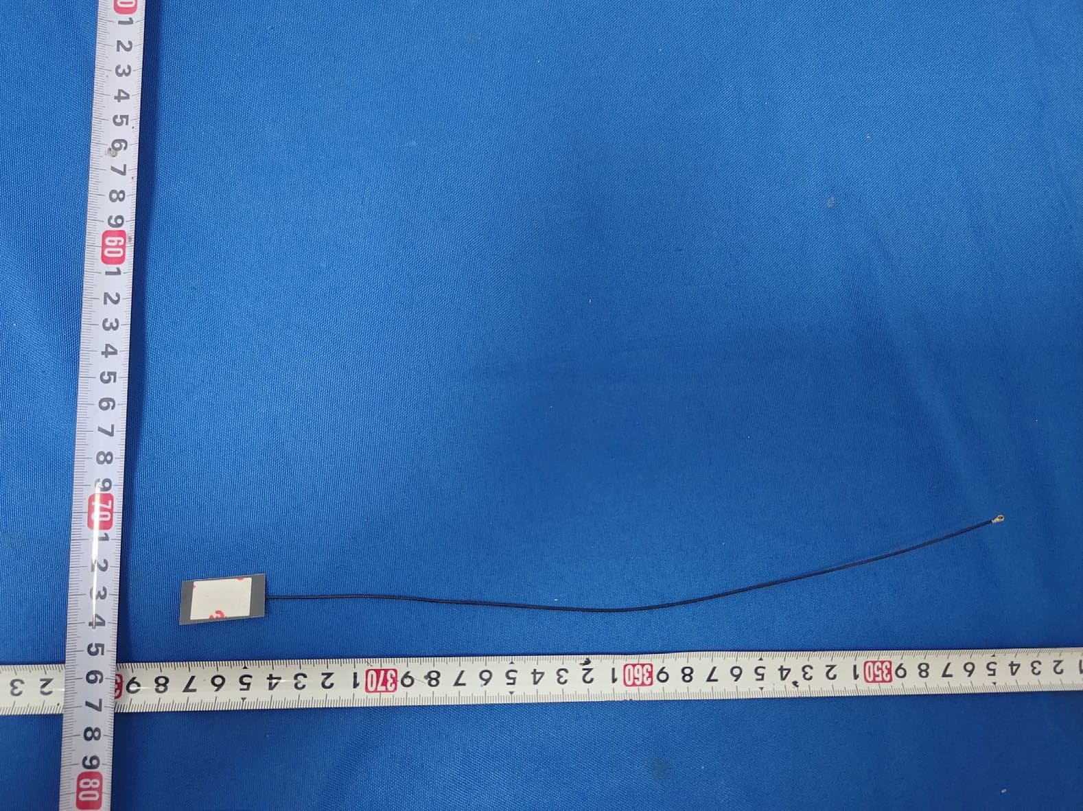
TLZ-CM689
May 06, 2026AW-CM689
Equipment Class
DSS - Part 15 Spread Spectrum TransmitterTLZ-CU640
Dec 23, 2025IEEE802.11 a/b/g/n/ac/ax and Bluetooth LE 5.4 LGA Module
Equipment Class
NII - Unlicensed National Information Infrastructure TXTLZ-CU668
Nov 25, 2025IEEE802.11 a/b/g/n/ac/ax and Bluetooth LE 5.4 LGA Module
Equipment Class
DTS - Digital Transmission SystemTLZ-CU597
Nov 24, 2025IEEE 802.11 a/b/g/n 1T1R WLAN and Bluetooth Low Energy Microcontroller Module
Equipment Class
NII - Unlicensed National Information Infrastructure TX