TMGG1JDDMN001Scan Tool
G.I.T CO.,LTD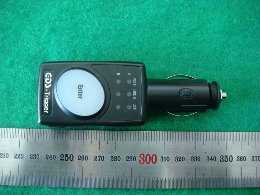
Click to zoom
Application Details
- Equipment Class
- DSS - Part 15 Spread Spectrum Transmitter
- Date of Grant
- Mar 30, 2014
- Application Purpose
- Original Equipment
- Date of Application
- Mar 30, 2014
- Equipment Note
- Scan Tool
- Frequency Range
- 2402.00000000 - 2480.00000000
- Company
- G.I.T CO.,LTD
- Country
- South Korea
Documents & Files
Document Text
Text extracted from the exhibit documents filed with the FCC. Open a document above to read the original.
Users Manual
GDS User’s Manual 1 G | Before Use Read the instructions thoroughly for proper operation of your GDS M. This manual contains information needed for using GDS M. The manual is subject to change without prior notice. Git assumes no liability for the Application which GIT do not produce GDS M application includes the several functions for uploading and downloading data. GIT assumes no liability for the fee due to the use of data Safety Warning and Caution before Use This section contains WARNING and CAUTION for safe usage of GDS M. Before use, the user should read the following information. WARNING This indicates incorrect handling may result in a major accident involving death or serious injury. The VCI should be secured in a safe location when operating the vehicle to avoid interference with other vehicle equipment. Only use the specified adapters and cables when connecting the VCI module. (7~35VDC) Ensure all cables are properly connected during operation. Do not disconnect communication cable or power cables unless finished with the equipment. When using the trigger module, ensure that the module is installed in a safe and secure location to avoid interference with other vehicle equipment. Do not disassemble the VCI module. Use only genuine accessory parts supplied by GIT. Never connect the device to equipment rather than vehicles. Products are to be stored within the right temperatures. (Refer to CAUTION) 2 G | CAUTION This indicates incorrect handling may lead to injury or damage to property. Under certain conditions more serious consequences may result. Do not remove the rubber shield from the VCI. Keep liquids and other contaminants away from the VCI. Do not drop the VCI. Do not place any objects (tools, manuals, etc.) on the VCI. Observe correct polarity when connecting the battery supply extension cable. When connecting cables under the hood, secure the cables to avoid damage caused by hot or moving parts. Unplugging the DLC and USB cables from the VCI module must only be done after releasing the cable connector lock tap(s). USB cable must be connected to VCI module in order to upgrade any vehicle ECU or VCI firmware. Properly store all components when not in use. Do not use cables as carrying handles. Do not store products in places where; Extremely high or low temperature (Refer to feature of products) Extremely high or low humidity (Refer to feature of products) Inside a vehicle during summer season for a long time Exposed to direct rays Avoid a shock or vibrations or under heavy weight. Avoid a shock or vibrations during shifting. Keep products away and store from moisture. GIT is not responsible for those causes that are generated by PCs, which are not recommended by GIT. Keep products away from flammable substances or places where fierce static electricity can occur. Products and accessories are not to be coated or painted with chemical substances or acid that can corrode the equipment. Do not expose the equipment to X-ray or Microwave. This might cause severe damage to the equipment. 3 G | Thank you for purchasing the Global Diagnostic System (GDS). Read the instructions thoroughly for proper operation of your Global Diagnostic System This Manual is copyrighted by Global Information Technology Co., Ltd. All rights reserved. No part of this manual may be reproduced in any form without the prior written permission of Global Information Technology Co., Ltd. No patent liability is assumed with respect to the use of the information contained herein. ⓒ2005 Global Information Technology Co., Ltd. All Right Reserved. Global Diagnostic System specifications and manual are subject to change without notice. Global Information technology Co., Ltd. assumes no liability for damage incurred directly or indirectly from error, omission or discrepancies between the Tablet PC, VCI, TPMS and the User Manual. Introduction Copyright Disclaimer 4 G | Introduction 5 G | Hardware VCI-II Component Identification and Functions VCI II Unlock button Unlock button for the pairing. When disconnecting VCI II from OBD-II(16Pin) on the vehicle side, unlock the pairing between . External Connector for USB cable Communication port for Connecting between VCI II and GDS PC with wire USB cable Bluetooth Paring Reset Button Reset button for re-pairing with Bluetooth GDS Trigger 1 2 3 6 G | GDS Trigger Component Identification and Functions Trigger Cigar Lighter connector Supplies the power to the GDS Trigger, should be connected to the Cigar Lighter on the vehicle Trigger Status LED Indicates VCI II communication status. Trigger Enter Button When using Trigger manually, the color of lights indicates the current status of trigger module. Notice Bluetooth Trigger Module must be inserted to Cigar Lighter when it is used for flight record (saving ECU input/output data on the vehicle) 1 2 3 7 G | VCI II Specifications Information Item Specifications CPU ARM 32-bit Cortex™-M3 (STM32F207VGT6) @ 120MHz Memory Flash Memory 1MByte, SRAM 128KByte Operating Voltage 7V - 35VDC Operating Temperature -20°C ~60°C Storage Temperature -40°C ~85°C Current Consumption Standby Mode 300mA @ 12V Wire Protocol USB 2.0 Full Speed(12Mbps) Wireless LAN Protocol Wireless LAN IEEE 802.11 a/b/g/n(20) Bluetooth Protocol Bluetooth 3.0, 2.1 (Class 1) Dimension 57.9 X 73.6 X 35.9 mm Weight 90 g Case PC+ABS GDS Trigger Specifications Information Item Specifications CPU ARM 32-bit Cortex™-M3 (STM32F205RGT6) @ 120MHz Memory Flash Memory 1MByte, SRAM 128KByte Operating Voltage 7V - 35VDC Operating Temperature -30°C ~70°C Storage Temperature -40°C ~85°C Current Consumption Standby Mode 70mA @ 12V Bluetooth Protocol Bluetooth 2.1 (Class 2) Dimension 38.3 X 111 X 25.3 mm Weight 55 g Case PC+ABS 8 G | VCI II and GDS Trigger Connection VCI II and GDS Trigger must be paired to transfer and save the data for Flight Record function from the vehicle to VCI II module. They are paired by Bluetooth communication system and must be set up as shown below. Prepar…
Text truncated - open the document above for the full version.
Cover Letter(s)
G.I.T Co., Ltd. GIT BLDG., 38-5 Garakbon-Dong, Songpa-Gu, Seoul, 138-801 Korea TEL: +82-2-2189-3353, FAX: +82-2-2189-3333 http://www.gitauto.com/ March 25, 2014 Federal Communications Commission Equipment Authorization Division, Application Processing Branch 7435 Oakland Mills Road Columbia, MD21046 RE: LETTER OF AGENT AUTHORIZATION We, the undersigned, hereby authorize SK TECH Co., Ltd.(Mr. Jongsoo, Yoon) to act on our behalf in all matters relating to application for equipment authorization. We also hereby certify that no party to the application authorized hereunder is subject to the denial of benefits, including FCC benefits, pursuant to Section 5301 of the Anti-Drug Abuse Act of 1988, 21 U.S.C.853(a). APPLICANT/AGENT CERTIFICATION AND AGREEMENT: All of the statements herein and the exhibits attached hereto, are true and correct to the best of my knowledge and belief. In accepting a Grant of Equipment Authorization issued by the TCB, under the authority of the FCC, as a result of the representations made in this application, the applicant is responsible for (1) labeling the equipment with the exact FCC ID specified in this application, (2) compliance statement labeling pursuant to the applicable rules, and (3) compliance of the equipment with the applicable technical rules. If the applicant is not the actual manufacturer of the equipment, appropriate arrangements have been made with the manufacturer to ensure that production units of this equipment will continue to comply with the FCC’s technical requirements. Authorizing an agent to sign this application, is done solely at the applicant’s discretion; however, the applicant remains responsible for all statements in this application. Sincerely, MIN KYU JEON/ Research Fellow
Cover Letter(s)
G.I.T Co., Ltd. GIT BLDG., 38-5 Garakbon-Dong, Songpa-Gu, Seoul, 138-801 Korea TEL: +82-2-2189-3353, FAX: +82-2-2189-3333 http://www.gitauto.com/ March 25, 2014 Federal Communications Commission Equipment Authorization Division, Application Processing Branch 7435 Oakland Mills Road Columbia, MD21046 TO WHOM IT MAY CONCERN Pursuant to Paragraphs §0.457 and 0.459 of the Commission's Rules (47 C.F.R) and Section §552(b)(4) of the Freedom of Information Act, G.I.T Co., Ltd. requests confidentiality for the following products: FCC ID Number ProductDescription (Model) TMGG1JDDMN001 Scan Tool(GDS Trigger) The requested Permanent and Short-Term Confidential exhibits art listed as follows: PERMANENT AND SHORT-TERM CONFIDENTIAL LIST Exhibit Description 1 Block Diagram 2 Operational Description 3 Schematics PERMANENT 4 Part List No other items submitted as part of the equipment authorization filing process are deemed confidential. The above exhibits contain G.I.T Co., Ltd. trade secrets and proprietary information that could be of benefit to our competitors regarding the design of our products. This material is not customarily available to the general public and we request that it be withheld from public inspection. Sincerely, MIN KYU JEON/ Research Fellow
External Photos
SK Tech Co., Ltd. Page 1 of 3 Photographs of EUT External view SK Tech Co., Ltd. Page 2 of 3 SK Tech Co., Ltd. Page 3 of 3
ID Label/Location Info
ID Label Location & Sample LABEL LOCATION: Label will be attached to the Rear of the product LABEL Drawing:
Internal Photos
SK Tech Co., Ltd. Page 1 of 4 Photographs of EUT Cover opened SK Tech Co., Ltd. Page 2 of 4 Main board SK Tech Co., Ltd. Page 3 of 4 Power board CHIP ANTENNA SK Tech Co., Ltd. Page 4 of 4 Power board(Bluetooth shielding can removed)
Operational Description
Dielectric Chip Antenna - Application Frequency Band[MHz] Bluetooth2400 ~ 2485 WiFi / Zigbee2400 ~ 2485 S-DMB2630 ~ 2655 Wibro 2300 ~ 2390 band1 : 2300 ~ 2327 band2 : 2331.5 ~ 2358.5 bnad3 : 2363 ~ 2390 Original Design Chip Antenna Data Sheet - P/N : SDBTPTR3015 - Dielectric Chip Antenna ■ ■■ ■ SDBTPTR3015 Dimension ParameterLWTABCDE Value[mm] 3.0 ± 0.1 1.5 ± 0.1 1.2 ± 0.1 1.00.550.41.10.65 Unless Specified tolerances are ± 0.05 mm Dielectric Chip Antenna ■ ■■ ■ Antenna Marking System ◀S SS S3 33 3 ① ①① ①② ②② ②③ ③③ ③ ITEMDESCRIPTION ① ①① ① Input SignalInput Signal ② ②② ② SerialSDBTPTR3015 ③ ③③ ③ Month ■ ■■ ■ Antenna PAD Information ◀S SS S3 33 3 123456 JanuaryFebruaryMarchAprilMayJune 789ABC JulyAugustSeptemberOctoberNovemberDecember Dielectric Chip Antenna ■ ■■■ AutoCAD Drawing of Reference PCB Design for SDBTPTR3015 Pro duct 41 2 3 Dielectric Chip Antenna ■ ■■ ■ PCB Drawing Top View Case #1 <Default> 1 11 12 22 2 3 33 3 4 44 4 Case #2 1 11 12 22 2 3 33 3 4 44 4 Case #3 1 11 12 22 2 3 33 3 4 44 4 Case #4 1 11 12 22 2 3 33 3 4 44 4 Bottom View <Equivalent Circuit> Dielectric Chip Antenna ■ ■■ ■ Matching Value Band (MHz) Matching Value (Default) Bluetooth / WiFi / Zigbee (2400 ~ 2485) Connector N/C Ant. 100pF 1.8pF 100 pF N/C S-DMB ( 2630 ~ 2655) Connector N/C Ant. 100pF 1.0nH 100 pF N/C Wibro (2300 ~ 2390) band1:2300~2327 band2:2331.5~2358.5 bnad3:2363~2390 Connector N/C Ant. 100pF 2.0pF 100 pF N/C Dielectric Chip Antenna - 3D Passive Gain ForBluetooth / WiFi / Zigbee ■ ■■ ■ Test Result for Ver 0.0 SWR & Smith chart3D Peak [dBi] Average [dBi] Efficiency [%] 2400MHz1.96-0.9780.18 2425MHz1.99-0.6685.92 2445MHz1.74-0.8582.42 2465MHz1.27-1.2575.12 2485MHz0.86-1.6468.59 ■ ■■ ■ Radiation PatternVer 0.0 3D Passive Dielectric Chip Antenna - 3D Passive Gain ForS-DMB ■ ■■ ■ Test Result for Ver 0.0 SWR & Smith chart3D Peak [dBi] Average [dBi] Efficiency [%] 2627MHz4.33-0.3891.80 2642MHz4.67-0.3692.06 2657MHz4.71-0.5688.02 ■ ■■ ■ Radiation PatternVer 0.0 3D Passive Dielectric Chip Antenna - 3D Passive Gain ForWibro ■ ■■ ■ Test Result for Ver 0.0 SWR & Smith chart3D Peak [dBi] Average [dBi] Efficiency [%] 2300MHz2.51-0.8482.52 2322.5MHz2.68-0.7883.71 2345MHz3.15-0.4590.20 2367.5MHz3.02-0.7883.76 2390MHz3.09-0.8682.12 ■ ■■ ■ Radiation PatternVer 0.0 3D Passive
RF Exposure Info
RF Exposure requirements Product name Scan Tool Model number GDS Trigger FCC ID TMGG1JDDMN001 Radio specification 2.4 GHz Bluetooth transceiver Antenna Integral chip antenna Power source DC 7 V ‐ DC 35 V According to the KDB 447498, the following standalone SAR test exclusion was considered to qualify for the SAR test exclusion. Tx frequency range 2402 MHz ‐ 2480 MHz Device category Mobile station Maximum conducted output power 0.68 mW (‐1.66 dBm) Limit 10 mW (distance = 5 mm) SAR test exclusion thresholds: [(max. power of channel, mW) / (min. separation distance, mm ] ∙ √f (GHz) ≤ 3.0 for 1‐g SAR and ≤ 7.5 for 10‐g extremity SAR MHz 5 10 15 20 25 293035404550 test separation distance (mm) 2450 10 19 29 38 48 565767778696 SAR test exclusion threshold (mW) The source‐based time‐averaged maximum conducted output power of the RF channel is less than 10 mW, and the minimum separation distance of 5 mm can be achived. Therefore the transmitter complies with the RF exposure requirements and the SAR is not required.
Test Report
SK Tech Co., Ltd. Report No.: SKT-RFC-140003 Page 2 of 24 Revision History of Report Rev. Revisions Effect pageReviewed by Date - Initial issue All Jongsoo Yoon March 20, 2014 SK Tech Co., Ltd. Report No.: SKT-RFC-140003 Page 3 of 24 TABLE OF CONTENTS 1 Summary of test results ................................................................................................. 4 2 Description of equipment under test (EUT) .................................................................. 5 3 Test and measurement conditions ................................................................................ 6 3.1. Test configuration (arrangement of EUT) ................................................................................ 6 3.2. Description of support units (accessory equipment)................................................................ 6 3.3. Interconnection and I/O cables................................................................................................ 6 3.4. Measurement Uncertainty (U) ................................................................................................. 6 3.5. Test date .................................................................................................................................. 6 4 Facilities and accreditations .......................................................................................... 7 4.1. Facilities................................................................................................................................... 7 4.2. Accreditations .......................................................................................................................... 7 4.3. List of test and measurement instruments............................................................................... 7 5 Test and measurements ................................................................................................. 8 5.1. Antenna requirement ............................................................................................................... 8 5.2. Maximum peak output power ..................................................................................................9 5.3. Carrier frequency separations and 20 dB bandwidth ............................................................ 11 5.4. Number of Hopping channels ................................................................................................14 5.5. Time of occupancy (Dwell time).............................................................................................16 5.6. Spurious emissions, Band edge, and Restricted bands ........................................................ 18 SK Tech Co., Ltd. Report No.: SKT-RFC-140003 Page 4 of 24 1 Summary of test results Requirement CFR 47 Section Result Antenna Requirement 15.203, 15.247(b)(4) Meets the requirements Maximum Peak Output Power 15.247(b)(1), (4) Meets the requirements Carrier Frequency Separation 15.247(a)(1) Meets the requirements 20dB Channel Bandwidth 15.247(a)(1) Meets the requirements Number of Hopping Channels 15.247(a)(iii), 15.247(b)(1) Meets the requirements Time of Occupancy (Dwell Time) 15.247(a)(iii) Meets the requirements Spurious Emission, Band Edge, and Restricted bands 15.247(d), 15.205(a), 15.209(a) Meets the requirements AC power line Conducted emissions 15.207(a) N/A ** The product is powered from a DC 12 V or 24 V lead-acid battery in a vehicle. SK Tech Co., Ltd. Report No.: SKT-RFC-140003 Page 5 of 24 2 Description of equipment under test (EUT) Product: Scan Tool Model: GDS Trigger Serial number: None (prototype) Model differences: Model name Difference Tested (checked) GDS Trigger Original (basic model that was fully tested) Note: All the differences were compared with the tested sample. Technical data: Power source 12 V/ 24 V lead-acid battery installed in vehicles Local Oscillator or X-Tal 25 MHz, 26 MHz Transmit Frequency 2402 MHz to 2480 MHz (79 channels) Antenna Type Integral chip antenna, peak gain: 1.99 dBi Type of Modulation GFSK RF Output power -1.66 dBm (measured conducted RF power) Note: I/O port Type Q'ty Remark Equipment Modifications none SK Tech Co., Ltd. Report No.: SKT-RFC-140003 Page 6 of 24 3 Test and measurement conditions 3.1. Test configuration (arrangement of EUT) The measurements were taken in continuous transmitting mode using the TEST MODE. For controlling the EUT as TEST MODE, the test program and the cable assembly were provided by the applicant. USB Interface TEST JIG PC Debug AC Mains DC input EUT DC Power Supply 3.2. Description of support units (accessory equipment) The following support units or accessories were used to form a representative test configuration during the tests. # Equipment Manufacturer Model No. Serial No. 1 PC DELL INC. 7XH86BX 17261795085 2 TEST JIG - - - Note: 1) For control of the RF module via USB interface at the Debug port(SPI) in the EUT. 2) For radiated spurious emission measurements, the measurements were performed without PC after setting the radio module to TEST MODE. 3) If not otherwise stated, for modulating the transmitter, a pseudo random bit sequence with each pattern type DH5 for GFSK was used. The power setting value of 48 was used as the applicant provided. BC4 (Hardware ID 0x26) firmware version 6705 3.3. Interconnection and I/O cables The following support units or accessories were used to form a representative test configuration during the tests. Start End Cable # Name I/O port Name I/O port length (m) shielded (Y/N) 1 EUT Debug TEST JIG RJ-45 1.0 N 2 TEST JIG USB PC USB 2.0 N Note: 1) All the equipment/cables were placed in the worst-case configuration to maximize the emission during the test. 2) Grounding was established in accordance with the manufacturer’s requirements and conditions for the intended use. 3.4. Measurement Uncertainty (U) Measurement Item Combined Standard Uncertainty Uc Expanded Uncertainty U = k Uc (k = 2) Conducted RF power ±1.49 d…
Text truncated - open the document above for the full version.
Test Setup Photos
SK Tech Co., Ltd. Report No.: SKT-RFC-140001 Page 1 of 3 Photographs of the test set-up Radiated emissions - front view Radiated emissions - rear view SK Tech Co., Ltd. Report No.: SKT-RFC-140001 Page 2 of 3 Radiated emission test below 30 MHz Radiated emission test below 1 GHz SK Tech Co., Ltd. Report No.: SKT-RFC-140001 Page 3 of 3 Radiated emission test above 1 GHz
Contact Information
Applicant
JIHYUNG RYU(Research Engineer)
Test Firm
SK Tech Co., LTD.Yoon Jongsoo
Technical Specifications
| # | Rule Parts | Frequency Range | Power Output |
|---|---|---|---|
| 1 | 15C | 2.40 GHz - 2.48 GHz | 680.00 µW |
Other Applications from G.I.T CO.,LTD
TMGG1TDDMN015
Jan 25, 2023Scan Tool
Equipment Class
DSS - Part 15 Spread Spectrum Transmitter
TMGGEVCT101
Jan 08, 2023Scan Tool
Equipment Class
DTS - Digital Transmission System
TMGG1XDDMN001
May 13, 2014Scan Tool
Equipment Class
DTS - Digital Transmission System
TMGG1TDDMN006
Feb 03, 2014TPMS Module
Equipment Class
DSS - Part 15 Spread Spectrum Transmitter
TMGG1PDDMN001
Apr 18, 2007Scan Tool
Equipment Class
DCD - Part 15 Low Power Transmitter Below 1705 kHz