TMGGEVCT101Scan Tool
G.I.T CO.,LTD
Click to zoom
Application Details
- Equipment Class
- DTS - Digital Transmission System
- Date of Grant
- Jan 08, 2023
- Application Purpose
- Original Equipment
- Date of Application
- Jan 08, 2023
- Equipment Note
- Scan Tool
- Frequency Range
- 2402.00000000 - 2480.00000000
- Company
- G.I.T CO.,LTD
- Country
- South Korea
Documents & Files
Document Text
Text extracted from the exhibit documents filed with the FCC. Open a document above to read the original.
Users Manual
1 User ’ s Manual | EV Charging Tester 2 User ’ s Manual | EV Charging Tester The EV charging tester is an equipment that determines the status of rapid/standard charges, high-voltage relay, and the presence of any abnormality in rapid and high-voltage charging path of the electric vehicle. 3 User ’ s Manual | Precautions Before inspecting or repairing high-voltage system, make sure to separate the safety plug to cut off the high voltage. Make sure to remove metal substances (watch, ring, and other metal products, etc.) from your body as they may cause high-voltage short circuit, which causes human and vehicle damages. Before starting any operation related to high voltage, please wear personal protective equipment for safety accident prevention. Please make sure that persons other than the operator wearing the protective equipment are prohibited from touching any part related to high-voltage parts. Remove foreign substances from the component and keep its cleanliness before and after using the equipment. Make sure you familiarize yourself with contents of the manual before use, in order to follow the procedures and instructions. Before using the equipment, please familiarize yourself with safety instructions for vehicle management, which were issued by the manufacturer of the vehicle. Use the equipment only in a well-ventilated space, and make sure to weak protective equipment (protective glasses and gloves, etc.). If the equipment is damaged by external shock, immediately stop using the equipment. If the equipment needs to be repaired, make sure to request the equipment manufacturer to perform the repair work. (Abnormal repair may become the cause of equipment damage) The equipment must not be exposed to rain or snow. The equipment must not be used for purposes other than the purpose of its manufacture. Do not leave the equipment being installed in the vehicle. If you do not use the equipment within its operating temperature range (0 – 40 °C), it may become the cause of its breakdown. These connectors are used for CP/PD voltage check and only trained professionals should use (or access). Precautions when handling high-voltage parts Precautions when utilizing the product 4 User ’ s Manual | Components Name Component Major function EV charging tester 1. Controls the conditions for the charging test. 2. Measures high voltage/current. GDS-Mobile 1. Performs the test sequence. 2. Indicates the test measured values. VCI II 1. Performs the vehicle diagnostic communication. (Connects the OBD terminal of the vehicle.) EV charging test components 5 User ’ s Manual | Name Major function LED status DC LINE Indicates the test results on rapid charging line. OK NG AC LINE Indicates the test results on standard charging line. OK NG ERROR Indicates the occurrence of system error. OK NG BT/Power - Indicates the power. - Indicates the connection status between the diagnostic apparatus and the test equipment. Connected Not connected (the light flickers once a second) Detailed description of the EV Charging Tester LED 6 User ’ s Manual | Advance Preparation Phase 1 Select [S/W Management]. Reference Before performing the function, VCI II must be connected to OBD connector on the vehicle. Phase 2 Select the type of vehicle to be measured. Entering into the function screen 7 User ’ s Manual | Phase 3 Select [Vehicle Charging Controller] -> [Charging Line Test] menu. 8 User ’ s Manual | Phase 1 After checking the purpose and condition of the EV charging test, press button at the bottom of the screen. Phase 2 Press button to connect the charging test equipment. Connection of the equipment 9 User ’ s Manual | Phase 3 Select the equipment in the research result. Phase 4 After the selected equipment is registered in “equipment currently being connected”, press button at the bottom of the screen. 10 User ’ s Manual | Phase 5 Once the BT signal of the equipment is connected normally, “BT/Power” LED of the equipment main body will be turned on with blue light. 11 User ’ s Manual | Major Functions It shows major functions of the EV charging line test, and the users can run a desired function by touching it. Main screen 12 User ’ s Manual | Menu Description of function This is a function for checking whether there is abnormality in the charging gun when an error occurs while the main test function is being operated, or if there is no change in voltage in connection test. Description Once you enter into the function screen, the self-test will be run right away, and the results will be shown on the screen after approximately 20 seconds. Reference Please run the corresponding function only after removing the charging test gun from the inlet. Notification The message below will appear when NG occurs. Self-test on the test equipment 13 User ’ s Manual | Menu Description of function This is a function that measures CP/PD voltage value to check whether the charging test equipment is normally connected to the inlet. Description The table at the top of the screen shows voltage value per operation and test results. The graph in the middle of the screen shows change in CP/PD voltage values of the controller, which are measured in real time through the diagnostic communication. Determination condition Charging gun connection test 14 User ’ s Manual | Menu Description of function The following 3 different functions will be performed as the main test functions: 1. Rapid charge relay test 2. Rapid charging line test 3. Standard charging line test 1. Rapid charge relay test This is a test that checks if there is abnormality in the rapid charge relay operation through a high-voltage rapid charge port. Determination condition Charging line test 15 User ’ s Manual | 2. Rapid charging line test This is a test that checks whether there is abnormality in the rapid charging line that goes through [high-voltage battery -> inverter -> charge port] through the path of the high-voltage rapid charge port. Determination …
Text truncated - open the document above for the full version.
Cover Letter(s)
G.I.T CO.,LTD 87, Macheon-ro, Songpa-gu Seoul South Korea 05655 Date: 01/05/2023 Federal Communications Commission Authorization and Evaluation Division 1435 Oakland Mills Road Columbia, MD 21046 Request of Confidentiality FCC ID: TMGGEVCT101 To Whom It may Concern: Pursuant to Sections 0.457 and 0.459 of the Commission`s Rules(CFR 47), and Section 552 (b) (4) of the Freedom of Information Act, G.I.T CO.,LTD. hereby requests confidentiality and treatment of certain information accompanying this application. The materials contain trade secrets and proprietary information not customarily released to the public. The public disclosure of these matters might be harmful to the Applicant and provide unjustified benefits to its competitors. We are also hereby request Short-Term Confidentiality for 180 days after the grant as outlined in Public Notice DA 04-1705. This provision will give G.I.T CO.,LTD. temporary confidentiality of commercially sensitive information prior to product release. The requested permanent and Short-Term Confidential exhibits are listed as follows: PERMANENT & SHORT-TERM CONFIDENTIAL LIST Exhibit Description PERMANENT 1 Block Diagram 2 Schematics 3 Part Lists 4 Operation Description 5 NA SHORT-TERM 6 Internal Photos 7 User Manual The Applicant understands that pursuant to Rule 0.457, disclosure of this application and all accompanying documentations, where applicable, will not be public before the date of the Grant for this application. Sincerely, Contact Name: JIHYUNG RYU Title: Senior Research Engineer
Cover Letter(s)
G.I.T CO.,LTD 87, Macheon-ro, Songpa-gu Seoul South Korea 05655 Date: 01/05/2023 Federal Communications Commission Authorization and Evaluation Division 1435 Oakland Mills Road Columbia, MD 21046 Letter of Authorization We, the undersigned, hereby authorize Geunki Son of Dt&C Co., Ltd. to act on our behalf in all manners relating to application for equipment authorization for FCC ID: TMGGEVCT101 including signing of all documents relating to these matters. Any and all acts carried out by Geunki Son of Dt&C Co., Ltd. on our behalf shall have the same affect as acts of our own. This authorization is valid until further written notice from G.I.T CO.,LTD. “I, the undersigned, hereby certify that we are not subject to a denial of federal benefits, that includes FCC benefits, pursuant to Section 5301 of the Anti-Drug Abuse Act of 1988, 21 U.S.C. 853(a).” Sincerely, Contact Name: JIHYUNG RYU Title: Senior Research Engineer
External Photos
FCC ID: TMGGEVCT101 Copyright Ⓒ 2023, Dt&C Co., Ltd. View 1 FCC ID: TMGGEVCT101 Copyright Ⓒ 2023, Dt&C Co., Ltd. View 2 FCC ID: TMGGEVCT101 Copyright Ⓒ 2023, Dt&C Co., Ltd. View 3 FCC ID: TMGGEVCT101 Copyright Ⓒ 2023, Dt&C Co., Ltd. View 4 <Port>
ID Label/Location Info
LABEL Label & Location
Internal Photos
FCC ID: TMGGEVCT101 Copyright Ⓒ 2023, Dt&C Co., Ltd. View 1 FCC ID: TMGGEVCT101 Copyright Ⓒ 2023, Dt&C Co., Ltd. View 2 FCC ID: TMGGEVCT101 Copyright Ⓒ 2023, Dt&C Co., Ltd. View 3 FCC ID: TMGGEVCT101 Copyright Ⓒ 2023, Dt&C Co., Ltd. View 4 FCC ID: TMGGEVCT101 Copyright Ⓒ 2023, Dt&C Co., Ltd. View 5 <Antenna>
Test Report
Report No.: DRTFCC2301-0001 FCC ID: TMGGEVCT101 This test report is prohibited to copy or reissue in whole or in part without the approval of Dt&C Co., Ltd. TRF-RF-238(06)210316 Pages: 57 / 77 TM 3 Conducted Spurious Emissions 3 (Te s t Channel : Highest) Report No.: DRTFCC2301-0001 FCC ID: TMGGEVCT101 This test report is prohibited to copy or reissue in whole or in part without the approval of Dt&C Co., Ltd. TRF-RF-238(06)210316 Pages: 58 / 77 5.5. Unwanted Emissions (Radiated) ▣ Test Requirements and limit, Part 15.247(d), Part 15.205, Part 15.209 In any 100 kHz bandwidth outside the frequency band in which the spread spectrum or digitally modulated intentional radiator is operating, the radio frequency power that is produced by the intentional radiator shall be at least 20 dB below that in the 100 kHz bandwidth within the band that contains the highest level of the desired power, based on either an RF conducted or a radiated measurement, provided the transmitter demonstrates compliance with the peak conducted power limits. If the transmitter complies with the conducted power limits based on the use of RMS averaging over a time interval, as permitted under paragraph (b)(3) of Part 15.247 the attenuation required under this paragraph shall be 30 dB instead of 20 dB. Attenuation below the general limits specified in §15.209(a) is not required. In addition, radiated emissions which fall in the restricted bands, as defined in §15.205(a), must also comply with the radiated emission limits specified in §15.209(a) (see §15.205(c)). - Part 15.209: General requirements Frequency (MHz) FCC Limit (uV/m) Measurement Distance (m) 0.009 – 0.490 2 400 / F (kHz) 300 0.490 – 1.705 24 000 / F (kHz) 30 1.705 – 30.0 30 30 Frequency (MHz) FCC Limit (uV/m) Measurement Distance (m) 30 ~ 88 100 ** 3 88 ~ 216 150 ** 3 216 ~ 960 200 ** 3 Above 960 500 3 **Except as provided in paragraph (g), fundamental emissions from intentional radiators operating under this section shall not be located in the frequency bands 54-72 MHz, 76-88 MHz, 174-216 MHz or 470-806 MHz. However, operation within these frequency bands is permitted under other sections of this part, e.g., §§15.231 and 15.241. Report No.: DRTFCC2301-0001 FCC ID: TMGGEVCT101 This test report is prohibited to copy or reissue in whole or in part without the approval of Dt&C Co., Ltd. TRF-RF-238(06)210316 Pages: 59 / 77 - Part 15.205(a): Restricted band of operation MHz MHz MHz MHz GHz GHz 0.009 ~ 0.110 0.495 ~ 0.505 2.173 5 ~ 2.190 5 4.125 ~ 4.128 4.177 25 ~ 4.177 75 4.207 25 ~ 4.207 75 6.215 ~ 6.218 6.267 75 ~ 6.268 25 6.311 75 ~ 6.312 25 8.291 ~ 8.294 8.362 ~ 8.366 8.376 25 ~ 8.386 75 8.414 25 ~ 8.414 75 12.29 ~ 12.293 12.519 75 ~ 12.520 25 12.576 75 ~ 12.577 25 13.36 ~ 13.41 16.42 ~ 16.423 16.694 75 ~ 16.695 25 16.804 25 ~ 16.804 75 25.5 ~ 25.67 37.5 ~ 38.25 73 ~ 74.6 74.8 ~ 75.2 108 ~ 121.94 123 ~ 138 149.9 ~ 150.05 156.524 75 ~ 156.525 25 156.7 ~ 156.9 162.012 5 ~ 167.17 167.72 ~ 173.2 240 ~ 285 322 ~ 335.4 399.90 ~ 410 608 ~ 614 960 ~ 1 240 1 300 ~ 1 427 1 435 ~ 1 626.5 1 645.5 ~ 1 646.5 1 660 ~ 1 710 1 718.8 ~ 1 722.2 2 200 ~ 2 300 2 310 ~ 2 390 2 483.5 ~ 2 500 2 655 ~ 2 900 3 260 ~ 3 267 3 332 ~ 3 339 3 345.8 ~ 3 358 3 600 ~ 4 400 4.5 ~ 5.15 5.35 ~ 5.46 7.25 ~ 7.75 8.025 ~ 8.5 9.0 ~ 9.2 9.3 ~ 9.5 10.6 ~ 12.7 13.25 ~ 13.4 14.47 ~ 14.5 15.35 ~ 16.2 17.7 ~ 21.4 22.01 ~ 23.12 23.6 ~ 24.0 31.2 ~ 31.8 36.43 ~ 36.5 Above 38.6 Report No.: DRTFCC2301-0001 FCC ID: TMGGEVCT101 This test report is prohibited to copy or reissue in whole or in part without the approval of Dt&C Co., Ltd. TRF-RF-238(06)210316 Pages: 60 / 77 5.5.1. Test Setup Refer to the APPENDIX I. 5.5.2. Test Procedures 1. The EUT is placed on a non-conductive table. For emission measurements at or below 1 GHz, the table height is 80 cm. For emission measurements above 1 GHz, the table height is 1.5 m. 2. The turntable shall be rotated for 360 degrees to determine the position of maximum emission level. 3. EUT is set 3 m away from the receiving antenna, which is varied from 1 m to 4 m to find out the highest emissions. 4. Maximum procedure was performed on the six highest emissions to ensure EUT compliance. 5. And also, each emission was to be maximized by changing the polarization of receiving antenna both horizontal and vertical. 6. Repeat above procedures until the measurements for all frequencies are complete. Note: Measurement Instrument Setting for Radiated Emission Measurements. - KDB558074 D01v05r02 - Section 8.6 - ANSI C63.10-2013 – Section 11.12 1. Frequency Range Below 1 GHz RBW = 100 or 120 kHz, VBW = 3 x RBW, Detector = Peak or Quasi Peak 2. Frequency Range > 1 GHz Peak Measurement > 1 GHz RBW = 1 MHz, VBW = 3 MHz, Detector = Peak, Sweep time = Auto, Trace mode = Max Hold until the trace stabilizes Average Measurement > 1 GHz 1. RBW = 1 MHz (unless otherwise specified). 2. VBW ≥ 3 x RBW. 3. Detector = RMS (Number of points ≥ 2 x Span / RBW) 4. Averaging type = power (i.e., RMS). 5. Sweep time = auto. 6. Perform a trace average of at least 100 traces. 7. A correction factor shall be added to the measurement results prior to comparing to the emission limit in order to compute the emission level that would have been measured had the test been performed at 100 percent duty cycle. The correction factor is computed as follows: 1) If power averaging (RMS) mode was used in step 4, then the applicable correction factor is 10 log(1 / D), where D is the duty cycle. 2) If linear voltage averaging mode was used in step 4, then the applicable correction factor is 20 log(1 / D), where D is the duty cycle. 3) If a specific emission is demonstrated to be continuous (≥ 98 percent duty cycle) rather than turning on and off with the transmit cycle, then no duty cycle correction is required for that emission. Test Mode T on (ms) T on + T off (ms) D = T on / (T on+off ) DCCF = 10 log(1 / D) (dB) TM 1 0.417 0.627 0.665 1 1.77 TM 2 0.234 0.627 0.373 2 4.28 TM 3 3.120 3.750 0.832 0 0.80 Note1: Where, T= Transmi…
Text truncated - open the document above for the full version.
Test Report
Report No.: DRTFCC2301-0001 FCC ID: TMGGEVCT101 This test report is prohibited to copy or reissue in whole or in part without the approval of Dt&C Co., Ltd. TRF-RF-238(06)210316 Pages: 2 / 77 Test Report Version Test Report No. Date Description Revised by Reviewed by DRTFCC2301-0001 Jan, 05. 2023 Initial issue SeungMin Gil JaeJin Lee Report No.: DRTFCC2301-0001 FCC ID: TMGGEVCT101 This test report is prohibited to copy or reissue in whole or in part without the approval of Dt&C Co., Ltd. TRF-RF-238(06)210316 Pages: 3 / 77 Table of Contents 1. General Information .................................................................................... 4 1.1. Description of EUT .......................................................................................................... 4 1.2. Declaration by the applicant / manufacturer ................................................................ 4 1.3. Testing Laboratory .......................................................................................................... 5 1.4. Testing Environment ....................................................................................................... 5 1.5. Measurement Uncertainty............................................................................................... 5 1.6. Test Equipment List ........................................................................................................ 6 2. Test Methodology ........................................................................................ 7 2.1. EUT Configuration ........................................................................................................... 7 2.2. EUT Exercise .................................................................................................................... 7 2.3. General Test Procedures ................................................................................................ 7 2.4. Instrument Calibration .................................................................................................... 7 2.5. Description of Test Modes.............................................................................................. 8 3. Antenna Requirements ............................................................................... 9 4. Summary of Test Results ......................................................................... 10 5. Test Result ................................................................................................. 11 5.1. Maximum Peak Conducted Output Power .................................................................. 11 5.1.1. Test Setup .................................................................................................................. 11 5.1.2. Test Procedures ........................................................................................................ 11 5.1.3. Test Results ............................................................................................................... 11 5.2. 6 dB Bandwidth ............................................................................................................. 18 5.2.1. Test Setup .................................................................................................................. 18 5.2.2. Test Procedures ........................................................................................................ 18 5.2.3. Test Results ............................................................................................................... 19 5.3. Power Spectral Density ................................................................................................. 26 5.3.1. Test Setup .................................................................................................................. 26 5.3.2. Test Procedures ........................................................................................................ 26 5.3.3. Test Results ............................................................................................................... 26 5.4. Unwanted Emissions (Conducted) .............................................................................. 33 5.4.1. Test Setup .................................................................................................................. 33 5.4.2. Test Procedures ........................................................................................................ 33 5.4.3. Test Results ............................................................................................................... 34 5.5. Unwanted Emissions (Radiated) .................................................................................. 58 5.5.1. Test Setup .................................................................................................................. 60 5.5.2. Test Procedures ........................................................................................................ 60 5.5.3. Test Results ............................................................................................................... 61 5.6. AC Power-Line Conducted Emissions ........................................................................ 64 5.6.1. Test Setup .................................................................................................................. 64 5.6.2. Test Procedures ........................................................................................................ 64 5.6.3. Test Results ............................................................................................................... 64 APPENDIX I .................................................................................................... 67 APPENDIX II ................................................................................................... 68 APPENDIX III ..................................................................................................…
Text truncated - open the document above for the full version.
Test Report
2019.09.24 RA-N1909-10 APPROVAL SHEET MODEL :BCM-LA100-AS Antenna layout Review Consent Approval Messrs. BnCOM Co.,Ltd RadiNa Co. ,Ltd TEL:+82-2-463-0373 FAX:+82-2-463-0374 PRODUCT APPROVAL SHEET GRSNO2908IC11 MODEL NAME BCM-LA100-AS REV. 1.0 Page 2 / 10 RADINA. Co., LTD Table of contents 1. Revision History 2. Product Information 2.1 General Features 2.2 Electrical Specifications 3. Pattern Specifications 4. Mat ching Network 5. Electrical Char acteristics 5.1 VSWR 5.2 Smith Chart 5.3 3D-PLOT 5.4 2D-GAIN 6. Passive Measurement 7. Measurement Process PRODUCT APPROVAL SHEET GRSNO2908IC11 MODEL NAME BCM-LA100-AS REV. 1.0 Page 3 / 10 RADINA. Co., LTD 1. Revision History NO. Before After Reason Date 1 2 3 4 5 6 7 8 9 10 11 12 13 PRODUCT APPROVAL SHEET GRSNO2908IC11 MODEL NAME BCM-LA100-AS REV. 1.0 Page 4 / 10 RADINA. Co., LTD 2. Product Information 2.1 General Features PART NUMBER GradiANT ANTENNA TYPE PCB Pattern Antenna APPLICATIONS Bluetooth 2.2 Electrical Specifications Frequency Range1 (TX) 2400MHz~2485MHz Frequency Range1 (RX) 2400MHz~2485MHz IMPEDANCE 50 V.S.W.R TX 2400MHz 2485MHz 5↓ 5↓ RX 2400MHz 2485MHz 5↓ 5↓ RADIATION PATTERN Omni-directional POLARIZATION Linear PRODUCT APPROVAL SHEET GRSNO2908IC11 MODEL NAME BCM-LA100-AS REV. 1.0 Page 5 / 10 RADINA. Co., LTD 3. Pattern Specifications 4. Matching Network Capacitor value can be changed depending on different situation PRODUCT APPROVAL SHEET GRSNO2908IC11 MODEL NAME BCM-LA100-AS REV. 1.0 Page 6 / 10 RADINA. Co., LTD 5. Electrical Characterristics 5.1 VSWR 5.2 SMITH CHART PRODUCT APPROVAL SHEET GRSNO2908IC11 MODEL NAME BCM-LA100-AS REV. 1.0 Page 7 / 10 RADINA. Co., LTD 5.3 3D-PLOTs 5.4 2D-GAIN PRODUCT APPROVAL SHEET GRSNO2908IC11 MODEL NAME BCM-LA100-AS REV. 1.0 Page 8 / 10 RADINA. Co., LTD 6. Passive Measurement 1 2 3 4 5 6 7 8 9 10 Frequency(MHz) 2400 2405 2410 2415 2420 2425 2430 2435 2440 2445 Efficiency(dB) -3.27 -3.27 -3.17 -3.12 -3.26 -3.21 -2.97 -2.69 -2.56 -2.66 Efficiency(%) 47.07 47.15 48.15 48.80 47.19 47.75 50.43 53.78 55.44 54.25 TRG(dB) -3.27 -3.27 -3.17 -3.12 -3.26 -3.21 -2.97 -2.69 -2.56 -2.66 TRG Theta (dB) -3.62 -3.61 -3.52 -3.46 -3.60 -3.56 -3.31 -3.03 -2.90 -2.99 TRG Phi (dB) -14.36 -14.39 -14.36 -14.35 -14.47 -14.32 -14.30 -14.02 -13.86 -13.97 UHRG(dB) -6.76 -6.74 -6.64 -6.59 -6.73 -6.69 -6.47 -6.20 -6.08 -6.20 UHRG/TRG(%) 44.83 44.92 44.97 44.96 44.96 44.83 44.75 44.63 44.48 44.26 H-Plane -1.76 -1.64 -1.43 -1.26 -1.32 -1.19 -0.88 -0.57 -0.42 -0.51 E1-Plane, AVG(dB) -4.39 -4.39 -4.32 -4.25 -4.40 -4.37 -4.11 -3.82 -3.69 -3.76 E2-Plane, AVG(dB) -4.89 -4.87 -4.77 -4.71 -4.86 -4.81 -4.57 -4.29 -4.13 -4.23 Peak Gain(dB) -0.93 -0.80 -0.59 -0.42 -0.49 -0.30 0.02 0.36 0.56 0.50 Directivity(dB) 2.35 2.47 2.58 2.70 2.77 2.91 3.00 3.06 3.13 3.16 Minimum Gain(dB) -18.20 -17.71 -17.21 -16.87 -16.57 -16.00 -15.70 -15.30 -14.95 -14.70 11 12 13 14 15 16 17 18 19 20 Frequency(MHz) 2450 2455 2460 2465 2470 2475 2480 2485 2490 2497 Efficiency(dB) -2.80 -2.71 -2.51 -2.55 -2.69 -2.80 -2.99 -3.08 -2.95 -3.05 Efficiency(%) 52.43 53.63 56.08 55.58 53.81 52.47 50.23 49.17 50.72 49.60 TRG(dB) -2.80 -2.71 -2.51 -2.55 -2.69 -2.80 -2.99 -3.08 -2.95 -3.05 TRG Theta (dB) -3.13 -3.03 -2.84 -2.88 -3.02 -3.13 -3.33 -3.42 -3.29 -3.39 TRG Phi (dB) -14.18 -14.10 -13.88 -13.92 -14.11 -14.17 -14.27 -14.33 -14.17 -14.17 UHRG(dB) -6.35 -6.28 -6.10 -6.16 -6.32 -6.46 -6.67 -6.77 -6.66 -6.78 UHRG/TRG(%) 44.15 43.92 43.78 43.58 43.36 43.10 42.89 42.76 42.57 42.31 H-Plane -0.67 -0.61 -0.46 -0.55 -0.74 -0.90 -1.16 -1.34 -1.29 -1.53 E1-Plane, AVG(dB) -3.89 -3.78 -3.58 -3.59 -3.73 -3.83 -3.99 -4.07 -3.92 -3.97 E2-Plane, AVG(dB) -4.38 -4.26 -4.08 -4.12 -4.25 -4.37 -4.57 -4.66 -4.52 -4.61 Peak Gain(dB) 0.38 0.44 0.65 0.56 0.37 0.22 0.00 -0.19 -0.13 -0.38 Directivity(dB) 3.18 3.14 3.16 3.11 3.06 3.02 2.99 2.89 2.82 2.66 Minimum Gain(dB) -14.89 -14.95 -14.82 -14.93 -15.29 -15.55 -16.15 -16.57 -16.41 -16.95 Average Efficiency -2.91dBi, 51.19% Peak Gain 0.65 dBi PRODUCT APPROVAL SHEET GRSNO2908IC11 MODEL NAME BCM-LA100-AS REV. 1.0 Page 9 / 10 RADINA. Co., LTD 7. Measurement Process 7.1 SWR / Return loss Set Condition Network Analyzer Agilent 8753ES Cable Semi-ridid (40mm, 60mm) Test condition 7.2 Gain Antenna gain is measured in the anechoic chamber of this company. Anechoic Chamber for Antenna Gain Measurement PRODUCT APPROVAL SHEET GRSNO2908IC11 MODEL NAME BCM-LA100-AS REV. 1.0 Page 10 / 10 RADINA. Co., LTD 7.3 Gain test block diagram Active test Sysetm - TRP, NHPRP,UHRP - TIS, NHPIS, UHIS - Relative Sensitivity Passiver test Sysetm - Efficiency - Peak Gain, Avg, Gain - Min, Max PWR
Test Setup Photos
FCC ID: TMGGEVCT101 Copyright Ⓒ 2023, Dt&C Co., Ltd. Test Setup photographs EUT Position: X-axis EUT Position: Y-axis EUT Position: Z-axis FCC ID: TMGGEVCT101 Copyright Ⓒ 2023, Dt&C Co., Ltd. Test Setup Photo of Radiated Measurement (0.009 ~ 30MHz) FCC ID: TMGGEVCT101 Copyright Ⓒ 2023, Dt&C Co., Ltd. Test Setup Photo of Radiated Measurement (Below 1GHz) FCC ID: TMGGEVCT101 Copyright Ⓒ 2023, Dt&C Co., Ltd. Test Setup Photo of Radiated Measurement (Above 1GHz) FCC ID: TMGGEVCT101 Copyright Ⓒ 2023, Dt&C Co., Ltd. Test Setup Photo of AC Line Conducted Measurement
Contact Information
Applicant
JIHYUNG RYU(Research Engineer)
Test Firm
Dt&C Co., Ltd.Lee Sang-Wook
Technical Specifications
| # | Rule Parts | Frequency Range | Power Output |
|---|---|---|---|
| 1 | 15C | 2.40 GHz - 2.48 GHz | 3.00 mW |
Other Applications from G.I.T CO.,LTD
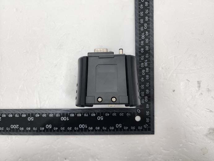
TMGG1TDDMN015
Jan 25, 2023Scan Tool
Equipment Class
DSS - Part 15 Spread Spectrum Transmitter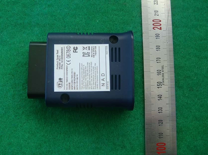
TMGG1XDDMN001
May 13, 2014Scan Tool
Equipment Class
DTS - Digital Transmission System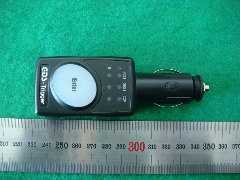
TMGG1JDDMN001
Mar 30, 2014Scan Tool
Equipment Class
DSS - Part 15 Spread Spectrum Transmitter
TMGG1TDDMN006
Feb 03, 2014TPMS Module
Equipment Class
DSS - Part 15 Spread Spectrum Transmitter
TMGG1PDDMN001
Apr 18, 2007Scan Tool
Equipment Class
DCD - Part 15 Low Power Transmitter Below 1705 kHz