TMGG1PDDMN001Scan Tool
G.I.T CO.,LTD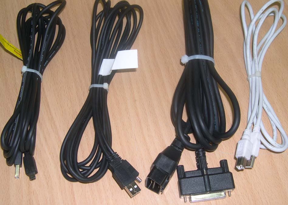
Click to zoom
Application Details
- Equipment Class
- DCD - Part 15 Low Power Transmitter Below 1705 kHz
- Date of Grant
- Apr 18, 2007
- Application Purpose
- Original Equipment
- Date of Application
- Apr 18, 2007
- Equipment Note
- Scan Tool
- Frequency Range
- 0.12500000 - 0.12500000
- Company
- G.I.T CO.,LTD
- Country
- South Korea
Documents & Files
Document Text
Text extracted from the exhibit documents filed with the FCC. Open a document above to read the original.
Users Manual
User’s Manual - 1 - Check before use Read me first ---------------------------- Introduction of G-scan ---------------------- Safety Warnings and Cautions before Use ------ G-scan Configuration Specification ---------------------------------- Introduction of component ---------------------- Introduction of function ------------------------- Basic Use of G-scan Power supplying ---------------------------- Power ON/OFF ---------------------------- Description for Main Component of H/W ----------- Description for Main Component of S/W Screen------ Connecting the DLC cable --------------------- Self Test Adapter connection ------------------ Configuration Setup ------------------------------------ User Information ----------------------------- Version ----------------------------------- Self Test ---------------------------------- Contents Check before using Module NO: A-00-001 User’s Manual - 2 - Vehicle Communication Function System Select -------------------- Fault Code Searching ------------ DTC Analysis ---------------------- DATA Analysis ------------------ Actuation Test --------------------------- Vehicle S/W Management --------- ECU Upgrade ------------------------------ OBD-II Function (CARB OBD-II) ----------------- Flight Recording -------------- PC Communication Software Installation -------------------------- Operating Program -------------------------- Appendix How to install Optional Items-------------------- O/S & Bootloader Update -------------------- G-scan and Peripherals Limited Warranty ---------- Disposal of Old Electrical and Electronic Equipment -------------------- Module NO: A-00-001 User’s Manual - 3 - User’s Manual - 4 - Read me first Check before use Module NO: A-00-002 Introduction Thank you for purchasing G-scan. This manual describes the basic information for using G-scan. Before using G-scan, please read this manual to be familiar with important information. Copyright Global Information Technology Co., Ltd copyrights this Manual. All rights reserved. No part of this manual may be reproduced in any form without the prior written permission of Global Information Technology Co., Ltd. No patent liability is assumed with respect to the use of the information contained herein. G-scan is registered trademark or trademark of Global Information Technology Corporation in the United States and/or other countries. ⓒ2007 Global Information Technology Co., Ltd. All Right Reserved. Disclaimer G-scan specifications and manual are subject to change without prior notice. Global Information technology Co., Ltd. assumes no liability for the products, which GIT do not produce. User’s Manual - 5 - Introduction of G-scan Check before use Module NO: A-00-003 Overview Comparing with the conventional diagnosis equipment, the interface of G-scan is configured to be easily operated. Anyone can easily use the G-scan to maintain the vehicle with maximized service efficiency. z Input using the Touch Screen Without complicated button operation, you can select menu and function on the screen directly. You can use diagnosis equipment easily. z 5.6′′ Color TFT LCD Adapting the 5.6′′ large size Color TFT LCD, various data can be shown on the same screen at the same time. z TPMS (Option) Embedding with TPMS module, it is possible to access to the TPMS sensor installed in the vehicle with wireless communication. z USB communication interface Using the USB communication interface, it is possible to connect with the diagnosis newly developed in future easily.. User’s Manual - 6 - Safety Warnings and Cautions Before Use Check before use Module NO: A-00-003 This section contains WARNINGS and CAUTIONS for safe usage of G-scan Before use, the user should read the following information. z The G-scan should be secured in a safe location when operated in the vehicle to avoid interference with other vehicle equipment. z Only use the specified adapters and cables when connecting the G- scan module. (7~35VDC). z Ensure all cables are properly connected during operation. Do not disconnect communication cable or power cables unless finished with the equipment. z Do not disassemble the G-scan module. z When updating G-scan, connect the external power (AC/DC adaptor) to supply stable power. z Ensure that the module is installed in a safe and secure location to avoid interference with other vehicle equipment. z Use only genuine accessory parts supplied by GIT. WARNING This indicates incorrect handling may result in a major accident involving death or serious injury. User’s Manual - 7 - z Never connect the device to equipment rather than vehicles. z Products are to be used within the right temperatures. (Refer to Specifications) z Products are to be stored within the right temperatures. (Refer to Specifications) z Use GIT products for their original purpose only. z This product is designed for technicians with proficient skills therefore all users must digest manuals fully before using the product. z Users have their own responsibility for Product damages, fire hazards and emitted gas caused by users with no full understanding of the Cautions and other information stated in the manual. z GIT products should never be tested or repaired by any one rather those authorized service technicians by GIT. z When exchanging rechargeable battery, comply with the method described in this manual by reading before exchanging it. z Use only rechargeable battery supplied from GIT. z Do not disconnect the rechargeable battery at one’s discretion. z Be careful that the rechargeable battery is not wet in water. z Do not put the rechargeable battery near the fire. z Do not impact to or prick the rechargeable battery with sharpen object. z Don not put the rechargeable battery into the microwave oven or high pressed vessel. z Do not throw or apply with physical impact to the rechargeable battery. Module NO: A-00-003 User’s Manual - 8 - z Be careful that the terminals of rechargeable battery are not shorted. z If the rechargeable batte…
Text truncated - open the document above for the full version.
Block Diagram
1. 315㎒ Receiver Block diagram ■ Circuit Description 1) SAW Filter SAW filter F1 is band pass filter. It filters out desired signal and delivers it to the LNA 2) RF IC (TDA5211) The TDA5211 is a very low power consumption single chip FSK/ASK superheterodyne receiver(SHR) for the frequency band 310 to 350MHz that is pin compatible with the ASK receiver TDA5201. The IC offers a high level of integration and needs only a few external components. The device contains a low noise amplifier(LNA), a double balanced mixer, a fully integrated VCO, a PLL synthesiser, a crystal oscillator, a limiter with RSSI generator, a PLL FSK demodulator, a data filter, a data comparator(slicer) and a peak detector. Additionally there is a power down feature to save battery life. 3) 10.1781㎒ Crystal & 10.7㎒ Filter fc = (315㎒ + 10.7㎒) / 32 = 10.1781㎒ SAW FILTER F1 RF IC TDA5211 U5 MPU U7 10.1781㎒ Crystal X2 10.7㎒ Filter F3 2. 433.92㎒ Receiver Block diagram ■ Circuit Description 1) SAW Filter SAW filter F2 is band pass filter. It filters out desired signal and delivers it to the LNA 2) RF IC (TDA5210) The TDA5210 is a very low power consumption single chip FSK/ASK superheterodyne receiver(SHR) for the frequency band 400 to 440MHz that is pin compatible with the ASK receiver TDA5200. The IC offers a high level of integration and needs only a few external components. The device contains a low noise amplifier(LNA), a double balanced mixer, a fully integrated VCO, a PLL synthesiser, a crystal oscillator, a limiter with RSSI generator, a PLL FSK demodulator, a data filter, a data comparator(slicer) and a peak detector. Additionally there is a power down feature to save battery life. 3) 13.2256㎒ Crystal & 10.7㎒ Filter fc = (433.92㎒ + 10.7㎒) / 32 = 13.2256㎒ SAW FILTER F2 RF IC TDA5210 U6 MPU U7 13.2256㎒ Crystal X3 10.7㎒ Filter F4 SYSTEM BLOCK DIAGRAM CONNECTOR 7~35V GND TXD RXD 5V Regulator Part LF Part MAIN CONTROLLER 315㎒ RF Controller 315㎒ RF Part 433㎒ RF Controller ANT 433㎒ RF Part
Cover Letter(s)
(Contact Person/Title) G.I.T Co., Ltd GIT BLDG., 38-5 Garakbon-Dong, Songpa-Gu, Seoul, 138-801 Korea Federal Communications Commission Equipment Authorization Division, Application Processing Branch 7435 Oakland Mills Road Columbia, MD21046 TO WHOM IT MAY CONCERN Pursuant to Paragraphs §0.457 and 0.459 of the Commission's Rules (47 C.F.R) and Section §552(b)(4) of the Freedom of Information Act, G.I.T Co., Ltd requests confidentiality for the following products: FCC ID Number Product Title / Model TMGG1PDDMN001 Scan Tool/G-scan For the product stated above, we request that the following information be held confidential: 1) Schematic diagrams 2) Bill of materials (Part List) No other items submitted as part of the equipment authorization filing process are deemed confidential. The above exhibits contain G.I.T Co., Ltd trade secrets and proprietary information that could be of benefit to our competitors regarding the design of our products. This material is not customarily available to the general public and we request that it be withheld from public inspection. Sincerely, Min Kyu, Jeon/ Senior Engineer
External Photos
SK TECH CO., LTD. Page 1 of 2 SKTTRT-070410-010 FCC ID: TMGG1PDDMN001 External Photographs of EUT <Photograph 1: Front View> <Photograph 2: Rear View> SK TECH CO., LTD. Page 2 of 2 SKTTRT-070410-010 FCC ID: TMGG1PDDMN001 < Photograph 3:Accessoris supplied with the EUT>
ID Label/Location Info
ID Label Location & Sample LABEL LOCATION: Label will be attached on the REAR of the product LABEL Drawing
Internal Photos
SK TECH CO., LTD. Page 1 of 6 SKTTRT-070410-010 FCC ID:TMGG1PDDMN001 Internal Photographs of EUT <Photograph 1: Cover removed> SK TECH CO., LTD. Page 2 of 6 SKTTRT-070410-010 FCC ID:TMGG1PDDMN001 <Photograph 2: RF Board View> <Photograph 3: RF Board Can Removed > SK TECH CO., LTD. Page 3 of 6 SKTTRT-070410-010 FCC ID:TMGG1PDDMN001 <Photograph 5: Main Board > SK TECH CO., LTD. Page 4 of 6 SKTTRT-070410-010 FCC ID:TMGG1PDDMN001 <Photograph 6: VCI Board > SK TECH CO., LTD. Page 5 of 6 SKTTRT-070410-010 FCC ID:TMGG1PDDMN001 <Photograph 7: Key-pad Board > SK TECH CO., LTD. Page 6 of 6 SKTTRT-070410-010 FCC ID:TMGG1PDDMN001 <Photograph 8: Charger Board > <Photograph 9: Inverter Board >
Operational Description
Operational Description The product, Model G-scan, is the diagnosis equipment, usually installed in a vehicle, to maintain the vehicle with maximized service efficiency and is made communication link with TPMS sensor to be provided the tire presure information at close from the tire of vehicle. The product transmit manually to TPMS sensor the LF signals and and deactivated automatically after transmitting LF signals then receive from the TPMS sensor the tire presure information. The activated "ON" time is about five seconds. * As shown below, in the case that the transmitter sends information that the tire is in abnormal condition, and that the receiver system has a trouble, the system will inform the user with lighting up Warning bulb. 5sec
Test Report
SK TECH CO., LTD. Page 1 of 13 Report No. : SKTTRT-070410-010 FCC ID: TMGG1PDDMN001 FCC-Certificate of Compliance Test Report No.: SKTTRT-070410-010 KOLAS No.: KT191 Applicant: G.I.T Co., Ltd. Applicant Address: GIT BLDG., 38-5 Garakbon-Dong, Songpa-Gu, Seoul, 138-801 Korea Manufacturer: G.I.T Co., Ltd. Manufacturer Address: GIT BLDG., 38-5 Garakbon-Dong, Songpa-Gu, Seoul, 138-801 Korea Device Under Test: Scan Tool FCC ID: TMGG1PDDMN001 Model No.: G-scan Receipt No.: SKTEU07-0136 Date of receipt: Feb. 15. 2007 Date of Issue: April 10, 2007 Location of Testing: SK TECH CO., LTD. 820-2, Wolmoon-Ri, Wabu-Up, Namyangju-Si, Kyunggi-Do, Korea Test Procedure: ANSI C63.4 / 2003 Test Specification: 47CFR, Part 15 Subpart C Equipment Class: DCD - Part 15 Low Power Transmitter Below 1705kHz Test Result: The above-mentioned device has been tested and passed. Tested & Reported by: Seong-Baek, Ko 2007. 04. 10 Approved by: Jong-Soo, Yoon 2007. 04. 10 Signature Date Signature Date Other Aspects: Abbreviations: · OK, Pass = passed · Fail = failed · N/A = not applicable ☞ ¾ This test report is not permitted to copy partly and entirely without our permission. ¾ This test result is dependent on only equipment to be used. ¾ This test result is based on a single evaluation of submitted samples of the above mentioned. ¾ This test report is the accredited testing items by Korea Laboratory Accreditation Scheme, which signed the ILAC-MRA. SK TECH CO., LTD. Page 2 of 13 Report No. : SKTTRT-070410-010 FCC ID: TMGG1PDDMN001 >> CONTENTS << 1. GENERAL ......................................................................................................................... 3 2. TEST SITE ........................................................................................................................ 3 2.1 Location ...................................................................................................................... 3 2.2 List of Test and Measurement Instruments ................................................................. 4 2.3 Test Date ..................................................................................................................... 4 2.4 Test Environment ........................................................................................................ 4 3. DESCRIPTION OF The EQUIPMENT UNDER TEST ............................................... 5 3.1 Rating and Physical Characteristics ........................................................................... 5 3.2 Equipment Modifications ··························································································· 5 3.3 Submitted Documents ································································································· 5 4. MEASUREMENT CONDITIONS .................................................................................. 6 4.1 Description of test configuration ................................................................................ 6 4.2 List of Peripherals .......................................................................................................6 4.3 Uncertainty ................................................................................................................. 6 5. TEST AND MEASUREMENTS ...................................................................................... 7 5.1 ANTENNA REQUIREMENT ................................................................................. 7 5.1.1 Regulation ............................................................................................................ 7 5.1.2 Result ...................................................................................................................7 5.2 RADIATED EMISSIONS(15.209) .......................................................................... 8 5.2.1 Regulation ............................................................................................................ 8 5.2.2 Measurement Procedure ...................................................................................... 8 5.2.3 Calculation of the filed strength limits .................................................................. 9 5.2.4 Test Results .......................................................................................................... 9 Table 1: Measured values of the Field strength (below 30MHz) .......................................................... 10 Table 2: Measured values of the Field strength (above 30MHz)........................................................... 10 5.3 CONDUCTED EMISSIONS(15.207) ······································································11 5.3.1 Regulation ···········································································································11 5.3.2 Test Procedure ····································································································11 5.3.3 Test Results ········································································································ 12 Table 3: Measured values of the Conducted Emissions·······································································12 Figure 1: Plot of the Conducted Emissions ........................................................................................ 13 SK TECH CO., LTD. Page 3 of 13 Report No. : SKTTRT-070410-010 FCC ID: TMGG1PDDMN001 1. GENERAL These tests were performed using the test procedure outlined in ANSI C63.4, 2003 for intentional radiators, and in accordance with the limits set forth in FCC Part 15.209, 15.207. The EUT (Equipment Under Test) has been shown to be capable of compliance with the applicable technical standards. We attest to the accuracy of data. All measurements reported herein were performed by SK Tech Co., Ltd. and were made under Chief Engineer’s supervision. We assume full responsibility for the completeness of these measurements and vouch for the qualifications of all persons taki…
Text truncated - open the document above for the full version.
Test Setup Photos
SK TECH CO., LTD. Page 1 of 2 SKTTRT-070410-010 FCC ID: TMGG1PDDMN001 Test set up photos <Radiated Emissions - Front View> <Radiated Emissions - Rear View> SK TECH CO., LTD. Page 2 of 2 SKTTRT-070410-010 FCC ID: TMGG1PDDMN001 <Conducted Emissions - Front View> <Conducted Emissions - Rear View>
Contact Information
Applicant
JIHYUNG RYU(Research Engineer)
Test Firm
SK Tech Co., LTD.Yoon Jongsoo
Technical Specifications
| # | Rule Parts | Frequency Range | Power Output |
|---|---|---|---|
| 1 | 15C | 0.125 MHz - 0.125 MHz | - |
Other Applications from G.I.T CO.,LTD
TMGG1TDDMN015
Jan 25, 2023Scan Tool
Equipment Class
DSS - Part 15 Spread Spectrum Transmitter
TMGGEVCT101
Jan 08, 2023Scan Tool
Equipment Class
DTS - Digital Transmission System
TMGG1XDDMN001
May 13, 2014Scan Tool
Equipment Class
DTS - Digital Transmission System
TMGG1JDDMN001
Mar 30, 2014Scan Tool
Equipment Class
DSS - Part 15 Spread Spectrum Transmitter
TMGG1TDDMN006
Feb 03, 2014TPMS Module
Equipment Class
DSS - Part 15 Spread Spectrum Transmitter