TMGGHDM-210000VCI TERMINAL DEVICE
G.I.T CO.,LTD
Click to zoom
Application Details
- Equipment Class
- JBP - Part 15 Class B Computing Device Peripheral
- Date of Grant
- Sep 13, 2005
- Application Purpose
- Original Equipment
- Date of Application
- Sep 13, 2005
- Equipment Note
- VCI TERMINAL DEVICE
- Company
- G.I.T CO.,LTD
- Country
- South Korea
Documents & Files
Document Text
Text extracted from the exhibit documents filed with the FCC. Open a document above to read the original.
Users Manual
1.Power on/off and method of switch operation 2. Installation of trigger module and cigar power cable 3. Scantool-Communication Open and Retry 4. Install configuration and Procedure of Hi-Diagnosis 5. Specifications and features User’s Manual Hi-Diagnosis 1 1. VCI Power On To turn on the VCI equipment, first of all, connect DLC cable from vehicle to VCI module and depressing the main switch. If diagnosis connector doesn’t applied for 16 pin connector, in other words, if battery power can’t be supplied from this diagnosis connector to VCI equipment, in this case, cigar power cable must be connected with cigar connector to supply the battery power with ACC stage from the ignition switch. In case of using electric supply from cigar power cable, please connect directly to battery by using battery extension cable. [Figure 1. Main switch of VCI main module] 1) Confirm the VCI operating condition VCI equipment has window for checking the VCI operating condition. This window shows that the condition of each function of VCI by showing with LEDs. Power on/off and method of switch operation H/W understanding for Hi-Diagnosis Module : A–01-005 (p.01) User’s Manual [Figure 2. LED status on window of VCI main module] POWER LED displays with turn VCI equipment on. Color of this LED reflects which function has been running on VCI equipment either diagnosis or flight record mode. Yellow refers to diagnosis mode and red is for flight record mode. VEH. COMM The condition of Vehicle Communication can be confirmed by LEDs. It depends on which function has been selected by user such as monitor DTC, sensor output or actuator operation by reading the blinking velocity of this LED with keep Vehicle Communication on. PC COMM As the way of communication between VCI and PC, it also confirmed with displayed LED color. Red color refers to wireless LAN and yellow is for USB cable. 2. VCI Power Off To turn off the VCI equipment, depressing the main switch for about 2.5 seconds or disconnecting the power supply cable. VCI equipment automatically turns off in case of disconnection of power supply cable. User’s Manual Module : A-01-005 (p.02) 3. Switch operation of trigger module 1) Switch operation of trigger module (Enter / Cancel) There are buttons for “ENTER” and “CANCEL” on the trigger module. The communication data is stored into memory of VCI by depressing “ENTER” button during the Flight Record mode. And the “ENTER” button can be undone by depressing the “CANCEL” button. 2) Lamp of trigger module (Power / Ready) Trigger module has two different LEDs. The one with red light refers to DC power supplied condition of VCI module and the other yellow light means recording status of communication data after depressing “ENTER” button. [Figure 3. Switches and LEDs of trigger module ] User’s Manual Module : A-01-005 (p.03) Trigger module of VCI equipment has two purposes. This trigger module sends the trigger signal to VCI main module when trouble occurrence. And trigger signal is sent to VCI by depressing the trigger button with Flight Record mode. According to this trigger signal, the VCI module starts to store the Flight Record Data. The VCI module receives ON/OFF signal from trigger module. In other words, trigger module detects ignition switch position and then sends ON/OFF signal to VCI module. Therefore the VCI module is turned ON/OFF automatically by turning the ignition switch as driver’s intention. And VCI module finally turns on with the signal from trigger module when turned ignition switch over the ACC stage. At this moment, VCI prepares for communication with ECU. The other purpose of trigger module is also supplies DC power to VCI module connected to the vehicle which isn’t applied for 16 pin(OBD II diagnosis connector) connector. 1. Installation of trigger module and cigar power cable Cigar jack from trigger module and round shape connector with 6pins are each connected with cigar connector on the vehicle and VCI module. Trigger module must be installed at the certain position to avoid disturbing their drive and also be considered that data captures promptly and quickly by sending the signal from trigger module. [Figure 1. Installation of trigger module] Installation of trigger module and cigar power cable H/W understanding for Hi-Diagnosis Module : A–01-004 (p.01) User’s Manual [Figure 2. Connection of cigar jack] [Figure 3. Connection of battery extension cable] User’s Manual Module : A-01-004 (p.02) 1. Vehicle and Control Module Selection If “ScanTool” menu item is selected before the vehicle/system selection through VIN selection, vehicle/system selection window appears as shown in [Figure 1]. Accurate system is necessary for the communication. In Hi-Diagnosis, there is no need to go through additional vehicle selection after the first selection for the use of other functions. System selection screen can be divided into 4 main parts: VIN selection, Configuration of “Scantool” function and “Fault Code Searching” condition, DTC input, and “Comments” input. [Figure 1. Vehicle Selection] Scantool-Communication Open and Retry Hi-Diagnosis program-DIAGNOSIS Module : A –04 –006 (p.01) User’s Manual 1) VIN Selection There are three ways to select vehicle. By Inputting Vehicle Identification Number consists of 17 figure codes combined by letters and numbers. By selecting vehicle, model year, and engine By using VIN Auto Detect function (1) Input of VIN with 17-figure codes combined with number and Letter There is a way to input all 17-figure code of VIN in the VIN input box. Another way is to input part of the 17-figure code and choose from the list. First, input all 17-figure code in the VIN input box and click “Go” button. “Vehicle”, “Model year”, “Engine” will automatically be chosen. Control modules of the corresponding vehicle appear for the inputted VIN code. [Figure 2. VIN Input - All of 17 figures] Another way is to input part of the 17-figure VIN code and click “Go” button. Window of VIN list will appear…
Text truncated - open the document above for the full version.
Block Diagram
5 5 4 4 3 3 2 2 1 1 DD CC BB AA ARM CPU : S3C2410A WLAN CARD (CFC) POWER SDRAM : HY57V643220 NAND FLASH : K9F5608U0B LOGIC : EPM3064ATC RELAY CPU : ATMEGA64 FLASH MEM : CS18LV02560BI KEY IN CPU : PIC16C73 RTC DC-IN(BATT) DATA BUS WLANVCI MAIN TRIGGER MODULE BOX CAR ECU-UNIT Hi-Diagnosis BLOCK DIAGRAM PC DLC CABLE USB BATT OUT USB UPGRADE Hi-Diagnosis <Doc>1.0 Hi-Diagnosis BLOCK DIAGRAM Custom 11Wednesday, June 29, 2005 Title SizeDocument NumberRev Date:Sheetof
External Photos
SK TECH CO., LTD. Page 1 of 2 SKT SKTFCE-050907-071 FCC ID : TMGGHDM-210000 External Photographs of EUT SK TECH CO., LTD. Page 2 of 2 SKT SKTFCE-050907-071 FCC ID : TMGGHDM-210000
ID Label/Location Info
SK TECH CO., LTD. Page 1 of 1 SKT SKTFCE-050907-071 FCC ID : TMGGHDM-210000 FCC ID Sample Label & Location Information LABELLING REQUIREMENTS PER ∫∫∫∫2.928 The Label shown shall be permanently affixed at a conspicuous location on the device and be readily visible to the user at the time of purchase. G.I.T Co., Ltd. VCI Main Module MODEL: GHDM-210000 FCC ID :TMGGHDM-210000 Contains FCC ID: NI3-IS20V35 This device complies with part 15 of the FCC Rules. Operation is subject to the following two conditions: (1)This device may not cause harmful interference, and (2) this device must accept any interference received, including interference that may cause undesired operation.
ID Label/Location Info
SK TECH CO., LTD. Page 1 of 1 SKT SKTFCE-050907-071 FCC ID : TMGGHDM-210000 FCC ID Label Sample
Internal Photos
SK TECH CO., LTD. Page 1 of 7 SKT SKTFCE-050907-071 FCC ID : TMGGHDM-210000 Internal Photographs of EUT SK TECH CO., LTD. Page 2 of 7 SKT SKTFCE-050907-071 FCC ID : TMGGHDM-210000 SK TECH CO., LTD. Page 3 of 7 SKT SKTFCE-050907-071 FCC ID : TMGGHDM-210000 SK TECH CO., LTD. Page 4 of 7 SKT SKTFCE-050907-071 FCC ID : TMGGHDM-210000 SK TECH CO., LTD. Page 5 of 7 SKT SKTFCE-050907-071 FCC ID : TMGGHDM-210000 SK TECH CO., LTD. Page 6 of 7 SKT SKTFCE-050907-071 FCC ID : TMGGHDM-210000 SK TECH CO., LTD. Page 7 of 7 SKT SKTFCE-050907-071 FCC ID : TMGGHDM-210000
Schematics
5 5 4 4 3 3 2 2 1 1 DD CC BB AA OM[3:2] : Clock Mode 00 : MPLL=Xtal, UPLL=Xtal 01 : MPLL=Xtal, UPLL=EXTCLK 10 : MPLL=EXTCLK, UPLL= Xtal 11 : MPLL= EXTCLK, UPLL=EXTCLK CPLD N.C:1.2.5.7.22.24.27.28.49.50.55.70.72.77 OM[1:0] : Bus Size 00 : Nand Boot 01 : Halfword (16 bit) 10 : Word (32 bit) 11 : Test Mode SDRAM (Address,Data,ADC,Clock,DMA,Timmer) NAND FLASH CPU /MEMORY/CPLD1.0 Hi-Diagnosis A3 11Wednesday, June 29, 2005 Title SizeDocument NumberRev Date:Sheetof CAN_D2 SPI_CLK L_FB_2 LD22 LD14 MD2 CAN_RX2 PWR_ON_OFF LD1 LED_CON2 MD4 LD15 L_FB LED_CON1 LD8 LD11 LD21 LD31 nCTS0 K_TXD MD0 VSS_IN SPI_SL nCLE CAN_RD LD24 NF_nCS LD27 TMS_1 LD13 UART_PC_RX LD21 CAN_D4 LD27 nRnB CAN_RX0 CAN_RX1 CLK_OUT MD1 LD12 LD29 LED_CON3 485_RXD LD0 CAN_WR LA22 CAN_D3 ADIN_2 nFWE MD3 MD4 nRXD2 LD25 LD30 LD28 LD6 nWAIT LA24 UART_PC_TX LD23 CAN_D0 LD16 CAN_D6 LA21 LD28 TDO_1 LD29 WLAN_CDP BUZZ_OUT J1850_IN LD31 nFCE SW_IN LnGCS0 WLAN_RST nTXD0 LED_CON5 MD0 LD7 K_RXD_OBD1 nTXD2 NF_DIR ADIN_1 CAN_D1 SPI_SO LD19 LD17 MD1 LD24 nFRE ADIN_3 LnOE LnGCS5 nALE LD19 LD25 CAN_D5 LnGCS5 TCK_1 MD5 LD16 UART_RXD MD5 MD3 LD5 LD20 nRXD0 CAN_ALE nFRE MD7 MD6 LED_CON4 J1850_OUT SW_OUT K_RXD_OBD2 nFWE DN1 MD6 LD3 TDI_1 SPI_SI LnWE LED_CON5 LD2 LD26 LD4 LD18 LED_CON0 LD26 L_TXD K_TXD1 LD20 LD9 LD22 LED_CON4 LD30 BLACK_CTRL LD18 LA23 MD2 CAN_CE BATT_IN LD17 DP1 nRTS0 LA25 ADIN_0 MD7 LD10 LD23 CAN_D7 DC_IN L_TXD1 3V3 3V3 3V3 3V3 3V3 +5V 3V3 3V3 3V3 3V3 3V3 3V3 Y3 12MHz U24 EPM3064ATC100-4 31 32 35 36 37 40 41 42 44 45 46 8 9 10 12 13 14 16 17 19 23 47 48 52 56 57 58 60 63 68 67 64 61 69 71 75 76 79 81 83 85 84 98 62 73 15 4 91 3 18 34 51 66 86 38 65 11 26 33 43 53 59 94 96 54 25 29 30 82 39 20 21 6 80 97 92 99 100 93 74 78 95 88 87 89 90 I/O I/O I/O I/O I/O I/O I/O I/O I/O I/O I/O I/O I/O I/O I/O I/O I/O I/O I/O I/O I/O I/O I/O I/O I/O I/O I/O I/O I/O I/O I/O I/O I/O I/O I/O I/O I/O I/O I/O I/O I/O I/O I/O #TCK #TDO #TMS #TDI VCC VCC VCC VCC VCC VCC GND GND GND GND GND GND GND GND GND I/O I/O I/O I/O I/O I/O VCC VCC I/O I/O I/O I/O I/O I/O I/O I/O I/O GND GND GND I/O I/O I/O I/O R980 U27 HY57V643220C(L)60/75 139 12 32 38 25 26 27 60 61 62 63 64 65 66 24 19 2 4 5 7 8 10 11 13 74 76 77 79 80 82 83 85 18 20 17 71 28 67 68 152941 44 46 52 16 59 43 6 22 23 31 33 34 36 37 39 40 42 45 47 48 50 51 53 54 56 58 72 78 86 84 49 55 81 75 35 3V33V33V3 VSS VSS VSS A0 A1 A2 A3 A4 A5 A6 A7 A8 A9 A10/AP RAS DQ0 DQ1 DQ2 DQ3 DQ4 DQ5 DQ6 DQ7 DQ8 DQ9 DQ10 DQ11 DQ12 DQ13 DQ14 DQ15 CAS CS WE DQM1 DQM2 CKE CLK 3V33V33V3 VSS VSS VSS DQM0 DQM3 3V3 VSS BA0 BA1 DQ16 DQ17 DQ18 DQ19 DQ20 DQ21 DQ22 DQ23 DQ24 DQ25 DQ26 DQ27 DQ28 DQ29 DQ30 DQ31 VSS VSS VSS VSS VSS 3V3 3V3 3V3 3V3 3V3 U23 74LVC245 2 3 4 5 6 7 8 9 19 1 18 17 16 15 14 13 12 11 20 10 A1 A2 A3 A4 A5 A6 A7 A8 G DIR B1 B2 B3 B4 B5 B6 B7 B8 3V3 GND JF1 CONN FLEX 24 1 3 5 7 9 11 13 15 17 19 21 23 2 4 6 8 10 12 14 16 18 20 22 24 1 3 5 7 9 11 13 15 17 19 21 23 2 4 6 8 10 12 14 16 18 20 22 24 U26 K9F5608U0A-YIB0 16 17 18 29 30 31 32 41 42 43 44 37 19 9 8 712 13 36 6 CLE ALE /WE D0 D1 D2 D3 D4 D5 D6 D7 VCC2 /WP /CE /RE R/BVCC1 VSS1 VSS2 GND RA12 1K 1234 5678 + C43 R970 R96 10K C41X RA15 0 1 2 3 45 6 7 8 U25A S3C2410A U16T15U17T16R15T17R16N13N12J11R12U12P17L13U14T13H17P16H16R17F2F1F4G3G4R11 H2G2H3H4 B14 D14 A14 C13 B13 D13 A13 C12 B12 G12 D12 E12 B11 A11 C11 G11 A10 B10 E10 D10 F10 A9 D9 E9 B9 C9 E8 B8 A8 D7 E7 C7 B7 A7 C6 F7 B6 D6 A5 C5 B5 D5 A4 A3 B3 A2 A1 B2 C3 B1 C2 C1 D2 D4 D1 E3 E2 E4 E1 G1G5D17E15E16E14E17F15C16G13E13R14U15 AIN0AIN1AIN2AIN3AIN4AIN5AIN6AIN7VrefEXTCLKCLKOUT0/GPH9CLKOUT1/GPH10MPLLCAPUPLLCAPOM2OM3XTIpllXTIrtcXTOpllXTOrtcTOUT0/GPB0TOUT1/GPB1TOUT2/GPB2TOUT3/GPB3TCLK0/GPB4TCLK1/EINT19/GPG11 nXDACK0/GPB9nXDACK1/GPB7 nXDREQ0/GPB10 nXDREQ1/GPB8 ADDR0/GPA0 ADDR1 ADDR2 ADDR3 ADDR4 ADDR5 ADDR6 ADDR7 ADDR8 ADDR9 ADDR10 ADDR11 ADDR12 ADDR13 ADDR14 ADDR15 ADDR16/GPA1 ADDR17/GPA2 ADDR18/GPA3 ADDR19/GPA4 ADDR20/GPA5 ADDR21/GPA6 ADDR22/GPA7 ADDR23/GPA8 ADDR24/GPA9 ADDR25/GPA10 ADDR26/GPA11 DATA0 DATA1 DATA2 DATA3 DATA4 DATA5 DATA6 DATA7 DATA8 DATA9 DATA10 DATA11 DATA12 DATA13 DATA14 DATA15 DATA16 DATA17 DATA18 DATA19 DATA20 DATA21 DATA22 DATA23 DATA24 DATA25 DATA26 DATA27 DATA28 DATA29 DATA30 DATA31 nXBACK/GPB5 nXBREQ/GPB6 nGCS0 nGCS1/GPA12nGCS2/GPA13nGCS3/GPA14nGCS4/GPA15nGCS5/GPA16 nOE nWAIT nWE OM0OM1 RA16 0 1 2 3 45 6 7 8 RA1 221 2 3 45 6 7 8 C39 10pF C40X C42 10pF 5 5 4 4 3 3 2 2 1 1 DD CC BB AA JTAG/Multi-ICE Connect Reset (External Interrupt , Reset , Power) CPU /JTAG1.0 Hi-Diagnosis A3 11Wednesday, June 29, 2005 Title SizeDocument NumberRev Date:Sheetof I2CLK TMS DO_S5 DO_K2 TDO DO_K14 nRXD2 TMS DO_K4 DO_R1 nRXD1WLAN_CDP TDI_1 DO_S2 DO_K3 TDO DO_K6 DO_CAN1 DO_R2 nRTS0 DO_L8 CABLE_ID3 DO_P5 LED_CON1 nRXD0 nTXD2 TCK nCTS0 DO_L1 CLK_OUT TCK_1 LED_CON3 SPI_SO DO_S1 nFCE nTXD0 DO_L3 nRXD2 nALE DO_R4 nCLE nRnB DO_CAN0 SPI_MA nFRE TDO_1 DO_L4 DO_P1 LED_CON2 SPI_SI DO_K7 nTXD1 DO_L5 DO_CAN2 CABLE_ID0 DO_L6 DO_P4 DO_P2 nFWE WLAN_RST DO_R5 DO_S4 I2DAT DO_S3 TCK TDI nTRST DO_P3 CABLE_ID1 CABLE_ID4 DO_P6 SPI_CLK DO_L7 SPI_SL VSS_FB LED_CON0 DO_R3 TDI DO_S7 DO_K5 DO_S6 DO_K8 nTRST DO_K1 TMS_1 CABLE_ID2 DO_L2 SPI_MA BAT_CHK BUZZ_OUT CABLE_ID5 CAN_INT J1850_INT DC_CHK nRESET BLACK_CHK nRESET nRESET_OUT SW_CHK LnSCAS LSCLK0 LnSRAS LnGCS6 nRESET LnWBE3 LnWBE0 LnWBE1 LnWBE2 LSCKE 1V8 3V3 3V3 3V3 3V3 3V3 3V3 3V3 3V3 3V3 1V8+5V BATT + C54 22uF/10V(T/T) D28 BAS16 UC55 104 UC41 104 RA13 22 1 2 3 45 6 7 8 UC24 104 UC1 104 U28 KIA7029AF 1 2 3 VCC GND OUT UC34 104 UC21 104 UC49 104 UC13 104 R10722 R109 1.5K R11210 UC28 104 UC52 104 UC36 104 UC7 104 UC47 104 U25C S3C2410A J12 J16 N14 N17 M16 M17 M15 M14 L15 L17 R8 U8 U10 T10 P10 J17J15M12P15G6J14D11C4C17C8J13P14L11G7K3L5M7N10R1N5 D8 E11 A15 A6 E5 B4 H14 K1 M6 N16 N9 T14 F6 F9 B17 F11 H15 M13 N15 H1J7M1N8M5M9U4F12E6A12D3G9F8F3C10D15F5H13K5T9P12R5 nRESET nRSTOUT/GPA21 EINT0/GPF0 EINT1/GPF1 EINT2/GPF2 EINT3/GPF3 EINT4/GPF4 EINT5/GPF5 EINT6/GPF6 EINT7/GPF7 EINT8/GPG0 EINT9/GPG1 EINT16/GPG8 EINT17/GPG9 EINT18/GPG10 nBATT_FLT PWREN RTCVDD (1.8V) VDDA_ADC (3.3V) VDDalive (1.8V)VDDalive…
Text truncated - open the document above for the full version.
Test Report
SK TECH CO., LTD. Page 1 of 17 SKT SKTFCE-050907-071 FCC ID : TMGGHDM-210000 Certificate of Compliance Test Report No.: SKTFCE-050907-071 NVLAP CODE : 200220-0 Applicant: G.I.T Co., Ltd. Applicant Address: GIT BLDG., 38-5 Garakbon-Dong, Songpa-Gu, Seoul, 138-801 Korea Manufacturer : G.I.T Co., Ltd. Manufacturer Address: GIT BLDG., 38-5 Garakbon-Dong, Songpa-Gu, Seoul, 138-801 Korea Product: Vehicle Communication Interface, VCI, VCI Main Module, GDS VCI, Hi-DS VCI FCC ID: TMGGHDM-210000 Model No.: GHDM-210000 Receipt No.: SKTEU05-0563 Date of receipt: Aug 20, 2005 Date of Issue: Sep 07, 2005 Testing location: SK TECH CO., LTD. 820-2, Wolmoon-Ri, Wabu-Up, Namyangju-Si, Kyunggi-Do, Korea Test Standards: ANSI C63.4 / 2003 Rule Parts: FCC part 15 Subpart B Equipment Class : Class B Digital Device Peripheral Test Result: The above mentioned product has been tested and passed. Prepared by: S.Y.Ye Tested by: J.S.Hyun/Engineer Approved by: D.H.Kang /Manager& Chief Engineer Signature Date Signature Date Signature Date Other Aspects : In tests, We made use of an authorized Wireless Lan. Abbreviations : · OK, Pass = passed · Fail = failed · N/A = not applicable ☞ •This test report is not permitted to copy partly without our permission. •This test result is dependent on only equipment to be used. •This test result is based on a single evaluation of one sample of the above mentioned. •This test report must not be used by the client to claim product endorsement by NVLAP or any agency of the U.S Government. • We certify that this test report has been based on the measurement standards that is traceable to the national or International standards. NVLAP Lab. Code: 200220-0 SK TECH CO., LTD. Page 2 of 17 SKT SKTFCE-050907-071 FCC ID : TMGGHDM-210000 》》 Contents 《《 Contents 2 List of Tables 2 List of Figures 2 1. General 3 2. Test Site 3 2.1 Location 3 2.2 List of Test and Measurement Instruments 4 2.3 Test Date 4 2.4 Test Environment 4 3. Description of the tested samples 5 3.1 Rating and Physical Characteristics 5 3.2 Submitted Documents 5 4. Measurement Conditions 6 4.1 Modes of Operation 6 4.2 List of Peripherals 6 4.3 Type of Used cables 7 4.4 Test Setup 7 4.5 Uncertainty 8 5. EMISSION Test 11 5.1 Conducted Emissions 11 5.2 Radiated Emissions 16 》List of Tables Table 1 List of test and measurement Equipment 4 Table 2 Test Data, Radiated Emissions 17 》List of Figures Figure 1 Spectral Diagram, LINE-PE 12 Figure 2 Test Data, LINE-PE 13 Figure 3 Spectral Neutral –PE 14 Figure 4 Test Data, Neutral-PE 15 SK TECH CO., LTD. Page 3 of 17 SKT SKTFCE-050907-071 FCC ID : TMGGHDM-210000 1. General This equipment has been shown to be capable of compliance with the applicable technical standards and was tested in accordance with the measurement procedures as indicated in this report. We attest to the accuracy of data. All measurements reported herein were performed by SK Tech Co., Ltd. and were made under Chief Engineer’s supervision. We assume full responsibility for the completeness of these measurements and vouch for the qualifications of all persons taking them. 2. Test Site SK TECH Co., Ltd. 2.1 Location 820-2, Wolmoon Ri, Wabu-Up, Namyangju-Si, Kyunggi-Do, Korea The test site is in compliance with ISO/IEC 17025 for general requirements for the competence of testing and calibration laboratories. This laboratory is accredited by NVLAP for NVLAP Lab. Code : 200220-0 and DATech for DAR-Registration No.:DAT-P-076/97-01 SK TECH CO., LTD. Page 4 of 17 SKT SKTFCE-050907-071 FCC ID : TMGGHDM-210000 2.2 List of Test and Measurement Instruments Table 1 : List of Test and Measurement Equipment z Conducted Disturbance Kind of Equipment Type S/N Calibrated until EMI Receiver ESHS10 862970/019 10.2005 Artificial Mains Network ESH2-Z5 834549/011 08.2006 EMI Receiver ESHS10 835871/002 10.2005 Artificial Mains Network ESH3-Z5 836679/018 08.2006 z Radiated Disturbance Kind of Equipment Type S/N Calibrated until EMI Receiver ESVS 10 825120/013 10.2005 EMI Receiver ESVS 10 834468/008 11.2005 Spectrum Analyzer R3361A 11730187 10.2005 Amplifier 8447F 3113A05153 08.2006 Log Periodic Antenna UHALP9107 1819 10.2005 Biconical Antenna BBA9106 91031626 10.2005 Open Site Cable N/A N/A N/A Antenna Turntable Driver 5907 N/A N/A Antenna Turntable controller 5906 N/A N/A Amp & Receiver connection cable N/A N/A N/A Amp & Spectrum connection cable N/A N/A N/A 50Ω Switcher MP59B 6100214538 N/A 2.3 Test Date Date of Application : Aug 20, 2005 Date of Test : Aug 25, 2005 ~ Aug 31, 2005 2.4 Test Environment See each test item’s description. SK TECH CO., LTD. Page 5 of 17 SKT SKTFCE-050907-071 FCC ID : TMGGHDM-210000 3. Description of the tested samples The EUT is the Vehicle Communication Interface(=VCI, VCI Main Module, GDS VGI, Hi-DS VCI). . 3.1 Rating and Physical Characteristics 1)General features Item Specifications 1.Micro controller ARM9(S3C2410A)@208MHz 2.Memory RAM 8MByte(4Banks X 512Kbits X 32bit) ROM 32MByte 3.Operating Voltage 7~35 VDC 4.Operating Temperature 14 °F ~158 °F(-10°C~70°C) : USB Mode 14 °F ~131 °F(-10°C~55°C) : WLAN 5.Operating Mode Diagnosis Function/ Flight Record Function 6.Current Consumption Typical 350mA @12V 7.Housing ABS& Rubber Shroud 8.Dimension 170x102x34mm 9.Weight 350g 2)PC Interface 1.Wire protocol USB 1.1 2.Wireless protocol Wireless LAN IEEE 802. 11b 3) Vehicle Communication Interface 1.CAN CAN2.0B 2.K-Line/L-Line ISO-9141, ISO-9141-CARB, KWP-2000 3.Commerical Veh. SAE-J1708, RS-232C 4.Data/ Control Line Melco Pull-Down UART 4) Added Interface 1.VSS Vehicle speed simulation 2.Voltage Output 5~20 VDC (Reprogram booster) 3.2 Submitted Documents N/A SK TECH CO., LTD. Page 6 of 17 SKT SKTFCE-050907-071 FCC ID : TMGGHDM-210000 4. Measurement Conditions Operating voltage of the EUT is 120V, 60Hz 4.1 Modes of Operation During all test, the test was conducted in data looping and ping test mode 4.2 List of Peripherals Equipment Manufacturer Model Name Serial No. Note PC Mitac Technology Corp. Series CA2001 4B19JNW740EW…
Text truncated - open the document above for the full version.
Test Setup Photos
SK TECH CO., LTD. Page 1 of 2 SKT SKTFCE-050907-071 FCC ID :TMGGHDM-210000 Test set up photos Photograph 1: Setup for Conducted Emissions SK TECH CO., LTD. Page 2 of 2 SKT SKTFCE-050907-071 FCC ID :TMGGHDM-210000 Photograph 2: Setup for Radiated Emissions
Contact Information
Applicant
JIHYUNG RYU(Research Engineer)
Test Firm
SK Tech Co., Ltd.Jae-Yeong Hyun
Technical Specifications
| # | Rule Parts | Frequency Range | Power Output |
|---|---|---|---|
| 1 | 15B | - | - |
Other Applications from G.I.T CO.,LTD
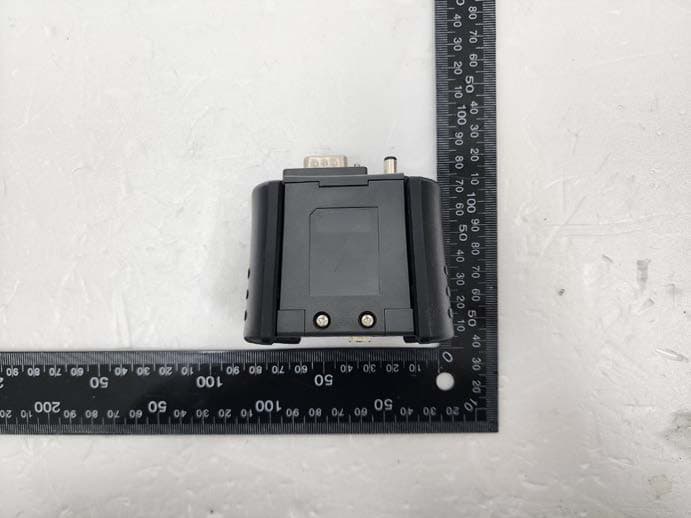
TMGG1TDDMN015
Jan 25, 2023Scan Tool
Equipment Class
DSS - Part 15 Spread Spectrum Transmitter
TMGGEVCT101
Jan 08, 2023Scan Tool
Equipment Class
DTS - Digital Transmission System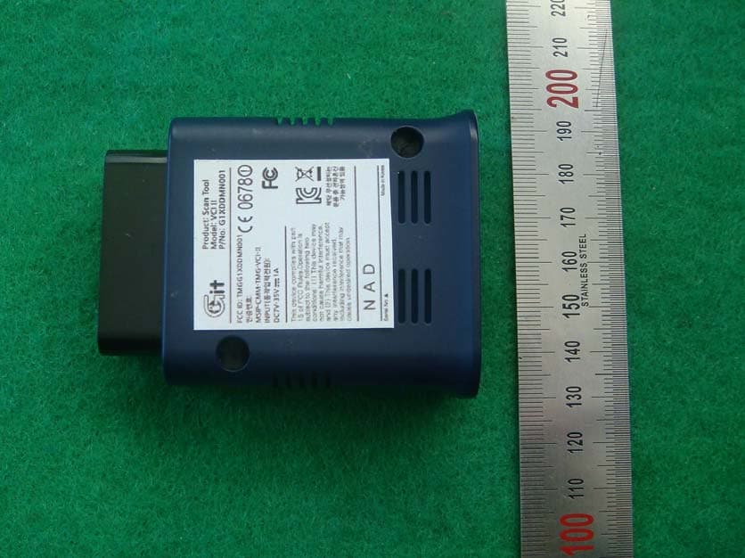
TMGG1XDDMN001
May 13, 2014Scan Tool
Equipment Class
DTS - Digital Transmission System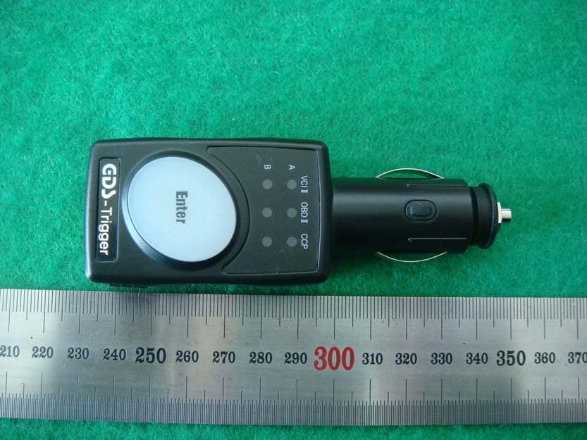
TMGG1JDDMN001
Mar 30, 2014Scan Tool
Equipment Class
DSS - Part 15 Spread Spectrum Transmitter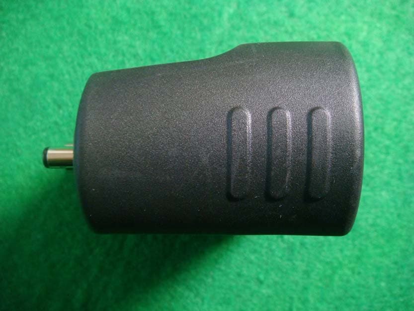
TMGG1TDDMN006
Feb 03, 2014TPMS Module
Equipment Class
DSS - Part 15 Spread Spectrum Transmitter