TT2CP100LBluetooth Internet Phone
ENUSTECH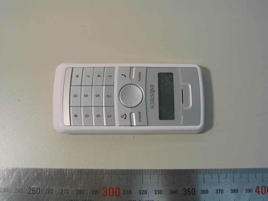
Click to zoom
Application Details
- Equipment Class
- DSS - Part 15 Spread Spectrum Transmitter
- Date of Grant
- Aug 21, 2006
- Application Purpose
- Original Equipment
- Date of Application
- Aug 21, 2006
- Equipment Note
- Bluetooth Internet Phone
- Frequency Range
- 2402.00000000 - 2480.00000000
- Company
- ENUSTECH
- Country
- South Korea
Documents & Files
Document Text
Text extracted from the exhibit documents filed with the FCC. Open a document above to read the original.
Users Manual
Enustech Inc. Revision No 1.0 Page: 1 User Manual Enustech Inc. Revision No 1.0 Page: 2 User Manual imFONE CP gives wireless freedom to the internet phone. Contents 1. Product Introduction 1.1 Features 1.2 Specifications 1.3 Packaging 2. imFONE CP Overview 3. Viewing the Menu Before connecting the imFONE CP Initialization Screen 3.1 CONNECT 3.2 BLUETOOTH 3.3 SETTINGS 4. Preparation Before Connecting 4.1 Components 4.2 imFONE S Installation 4.3 imFONE M Installation 5. Connecting the Bluetooth Devices 5.1 Pairing imFONE CP 5.2 Connecting imFONE CP 6. How to use 6.1 Initializing (Introductory) screen view 6.2 Menu Selection 6.3 Making Calls 6.4 Receiving Calls 6.5 Holding Calls 6.6 Ending Calls 6.7 Viewing the Recent Calls List 6.8 Returning to the [Start] menu. 6.9 How to use the Presenter 6.10 Muting Button Sound 6.11 Disconnecting Bluetooth 7. FAQ 8. Notice 9. Regulatory Notice 10. Address Information Enustech Inc. Revision No 1.0 Page: 3 User Manual Please fully charge the imFONE CP after purchasing 1. Product Introduction What is imFONE CP? ImFONE CP is a cordless internet phone which you can use as an internet phone in conjunction with your PC. With this easy to install phone and its stylish, mobile phone-like design, you can place a crystal clear phone call through the internet network. 1.1 Features ① Free internet phone calls between VoIP Softphone buddies ② Crystal clear sound through echo cancellation ③ Making calls/ Receiving calls ④ Multi-functions ⑤ Conference and video call functionality 1.2 Specifications - Bluetooth® Qualified: Bluetooth Ver. 1.2 Compliant (Class1) - Radio Frequency Range: 2.402 ~ 2.480 GHz - Transmit Power & Receive Sensitivity: 17dBm(Typical 15dBm), -85dBm - Service Distance: Up to 50 meters (164feet) on an open field - Service Profile: Cordless Telephone Profile - Security: 56 bit encryption - Display: 32X128 pixels, Monochrome - Power Source: Battery-Rechargeable 840mA Lithium-Ion Polymer Charger-USB charger (Current:460mA/h, Voltage:4.6~5.0V DC) TTA 24pin standard charger (for mobile phone) - Charging Time: USB Charger-3 hours ※ TTA 24pin standard charger(for mobile phone): 2.5 hours ※ Charging time can depend on the PC’s system capacity. - Operating Time: Standby-Up to 38 hours Talk Time-Up to 8 hours - Certification: SIG, CE, FCC, MIC - System Requirements: 2000/XP ※ A driver must be installed to use imFONE with Windows 98 systems. Enustech Inc. Revision No 1.0 Page: 4 User Manual 1.3 Packaging - imFONE CP Plus - imFONE CP Basic : imFONE S and the Manager program CD are not included in the package. 2.ImFONE CP Overview Enustech Inc. Revision No 1.0 Page: 5 User Manual 3. Viewing the Menu Before Connecting imFONE CP ◆ Initial Screen The initial screen is displayed before the imFONE CP is connected to the Bluetooth device (like the imFONE S, M or STAP-100). Please note that the antenna symbol( ) is not displayed before the connection is made between the imFONE CP and the Bluetooth device. Before connecting, the Menu selections displayed on the LCD are [CONNECT], [BLUETOOTH], [SETTINGS]. 3.1 CONNECT This menu is for connecting the imFONE CP with the inserted Bluetooth device. ▶ When the bond device information doesn’t exist on the imFONE CP, the message “No bond device exists” will be displayed and the introductory screen will be shown. At this point, the imFONE CP can be used after registering the device through the [BLUETOOTH] menu. ▶ When the bond device information exists on the imFONE CP, the device named imFONE S or imFONE M will automatically try to connect with the imFONE CP. After making a successful connection, the message ”Connected” will be displayed and it will be possible to return to the initial screen. Enustech Inc. Revision No 1.0 Page: 6 User Manual 3.2 BLUETOOTH ① PAIR DEVICE To use the internet phone through the imFONE CP, the Bluetooth dongle named imFONE S or imFONE M, must be registered on the imFONE CP. We call this is“ Pairing”. You can set up “Pairing” on the [PAIR DEVICE] menu. ※ Please refer to 5. Pairing for the steps on how to set up pairing. ② Bond Info The bond device information in the imFONE CP is displayed. ③ My Information The address and firmware version of the imFONE CP is displayed. 3.3 SETTINGS ① PRESENTER In the [SETTINGS] menu, if the Presenter is set to “On”, the imFONE CP can be used as a laser pointer. This setting will also allow you to move forward and backwards through an MS PowerPoint presentation using the (▲▼)arrow keys. ※ For more information, please refer to section 7.8 How to use Presenter. ② BUTTON SOUND You can turn on or mute button sound while pressing buttons. In the Settings menu, if the [BUTTON SOUND] is set to “off”, button sound will be muted. ※ For more information, please refer to section 7.9 Muting Button Sound 4. Preparation Before Connecting To use the internet phone and our dongle, imFONE Manager must be installed on the PC to provide the link between the internet phone and the imFONE CP(Bluetooth cordless phone). The Bluetooth device, named imFONE S or imFONE M, must be registered in the imFONE CP before it can provide a link between the computer and the phone. This is called “Pairing” and it needs to be set only once when you initially register bond device information. By changing the information, the imFONE CP can be paired with other Bluetooth devices. Enustech Inc. Revision No 1.0 Page: 7 User Manual 4.1 Components 4.2 imFONE S Installation ① Install an internet phone program, such as Skype, on the PC. ② Run the internet Phone program that was just installed. ※ Please refer to the internet phone program’s installation guide on their web site. ③ Insert the CD from the imFONE CP package and install the imFONE Manager program for the imFONE CP. Click next Click Install after choosing Install Location. Enustech Inc. Revision No 1.0 Page: 8 User Manual → Click Finish ④ After completing the installation, run imFONE Manager. ⑤Plug the imFONE S into the USB port of the PC. 4.3 imFONE M In…
Text truncated - open the document above for the full version.
Cover Letter(s)
JnJ Bldg.,5 th Yeoksam 2-dong,785-12, Gangnam-gu,Seoul 135-514,R.O.K Revision 1.0 1 - 1 Enustech Inc. Chief, Equipment Approval Services Federal Communications Commission PO Box 358315 Pittsburg, PA 15251-5315 Seoul, June 28, 2006 Authorization Letter Dear Sir or Madam: We, Enustech.,Inc. , hereby authorize O.N.R Tech Inc. 463-49, Sinlim-dong, Gwanak-gu, Seoul ,151-870, Republic of Korea To act as our agent and to process and sign on our behalf for equipment authorization under FCC Part 15, Subpart C. This authorization is applicable for the product: Codeless Phone (ImFONE CP) with FCC ID: TT2CP100L Sincerely, Signature : Printed Name: Seok Jin Kim Title : Manager Company Stamp:
Cover Letter(s)
JnJ Bldg.,5 th Yeoksam 2-dong,785-12, Gangnam-gu,Seoul 135-514,R.O.K Revision 1.0 1 - 1 Enustech Inc. Federal Communications Commission Authorization and Evaluation Division 7435 Oakland Mills Road Columbia, MD 21046 Seoul, June 28, 2006 REQUEST FOR CONFIDENTIALITY, FCC ID: TT2CP100L Pursuant to Sections 0.457(d)(1)(ii) and 0.459 of the Commission's Rules, the Applicant hereby requests confidential treatment of information accompanying as outlined below: • Schematic drawing • Bill of Materials • Block Diagram The above materials contain trade secrets and proprietary information not customarily released to the public. Public disclosure of these matters might be harmful to the Applicant and provide unjustified benefits to its competitors. The Applicant understands that pursuant to Rule 0.457(d)(1)(ii), disclosure of this Application and accompanying documentation will not be made before the date of the Grant for this application. Sincerely, Signature : Printed Name: Seok Jin Kim Title : Manager Company Stamp:
External Photos
Enustech Inc. Revision No : 1.0 Page: 1 External Photos 1. TOP View 2. Right side view Enustech Inc. Revision No : 1.0 Page: 2 External Photos 3. Bottom View 4. Left side view Enustech Inc. Revision No : 1.0 Page: 3 External Photos 5. 24Pins Connector view
ID Label/Location Info
Revision No : 1.0 Page: 1 of 1 Label and Location Enustech Inc. * Label location (printed on the case) *Label (printed on the case)
Internal Photos
Enustech Inc. Revision No : 1.0 1 Internal Photos 1. Internal Enustech Inc. Revision No : 1.0 2 Internal Photos 2. Top PCB View 3. Bottom PCB View Bluetooth BB Chipset Bluetooth Antenna Bluetooth RF Chipset Bluetooth X-tal Enustech Inc. Revision No : 1.0 3 Internal Photos 4. TOP View for Battery PCB 5. Bottom View for Battery PCB
Operational Description
Revision No : 1.1 Page: 1 of 2 EUT Description Enustech Inc. 1.Description ImFONE CP is a cordless internet phone which you can use as an internet phone in conjunction with your PC. With this easy to install phone by and its stylish, mobile phone-like design, you can place a crystal clear phone call through the internet network. The small, lightweight design is perfect for VoIP(Internet Phone) service at home or in the office. imFONE CP is a wireless client device for VoIP (Internet Phone) service running on your PC. You can also select from buddy list or dial directly using the keypad to make the call. ImFONE CP lets you make internet phone calls, through internet phone programs such as SKYPE or imTEL or Naver (Korean version internet phone solution) Long range 2.4GHz wireless technology allows to you use your imFONE CP up to a distance of 30 meters to provide you maximum freedom, control and flexibility. Equipped with a built-in laser pointer, imFONE CP also functions as a wireless presenter. You can navigate through your presentation pages using the arrow key of the keypad. 2. Features ① Free internet phone calls between VoIP Softphone buddies ② Crystal clear sound through echo cancellation ③ Making calls/ Receiving calls ④ Multi-functions ⑤ Conference and video call functionality 3. Specifications - Bluetooth® Qualified: Bluetooth Ver. 1.2 Compliant (Class1) - Radio Frequency Range: 2.402 ~ 2.480 GHz - Transmit Power & Receive Sensitivity: 17dBm(Typical 15dBm), -85dBm - Service Distance: Up to 50 meters (164feet) on an open field - Service Profile: Cordless Telephone Profile - Security: 56 bit encryption - Display: 32X128 pixels, Monochrome - Power Source: Battery-Rechargeable 840mA Lithium-Ion Polymer Charger-USB charger (Current:460mA/h, Voltage:4.6~5.0V DC) TTA 24pin standard charger (for mobile phone) - Charging Time: USB Charger-3 hours ※ TTA 24pin standard charger(for mobile phone): 2.5 hours ※ Charging time can depend on the PC’s system capacity. - Operating Time: Standby-Up to 38 hours Talk Time-Up to 8 hours - System Requirements: 2000/XP Revision No : 1.1 Page: 2 of 2 EUT Description Enustech Inc. 4. Equipment under test Data Entries Power Control? Yes Normal operation during battery charging? Yes Voltage ( Min, Nom , Max ) 3.3V, 3.8V, 4.2VDC Temperature ( Min, Nom , Max ) -10, +25, +60 Power supply Type 4.2VDC Battery Type if any (ex. Lithium Ion ) Lithium Polymer Antenna Gain (maximum) 0 dBi Antenna Type ( ex. Surface mounting type ) Ceramic Chip Antenna 5. General EUT Information Type Transmitter Receiver FCC Classification FHSS Sequence Spread Spectrum ( FHSS) FHSS Sequence Spread Spectrum ( FHSS) Operating frequency range 2402 – 2480 MHz 2402 – 2480 MHz Bands of operation 2.400 – 2.4835 GHz 2.400 – 2.4835 GHz Number of Channels 79 79 Channel Separation 1MHz 1MHz Type of Antenna Chip Antenna Chip Antenna Power Supply DC 3.7 V Lithum Ion Battery DC 3.7 V Lithum Ion Battery
RF Exposure Info
KTL Korea Testing Laboratory Page 1 of 49 TEST REPORT This test report only responds to the tested sample and shall not be reproduced except in full without written approval of the Korea Testing Laboratory. Tested and reported by Reviewed by Jong-Gon Ban, Engineer Seok-Jin Kim , Telecommunication Team Manager KOREA TESTING LABORATORY FG101-01-02-00 222-13, Guro-Dong Guro-Gu Seoul Korea 152-053 http://www.ktl.re.kr Ref. Report No. 06-341-25 Name and address of the applicant Enustech. Inc JnJ Bldg, 5 th Yeoksam 2-dong, 785-12, Gangnam_gu, Seoul, Republic of Korea Standard / Test regulation FCC Part2;OET Bulletin 65, Supplement C(July 2001) Test result Pass Incoming date : 05 th / July/ 2006 Test item(s) ; Bluetooth VoIP Phone Model; CP100L Manufacturer ; Enustech. Inc JnJ Bldg, 5 th Yeoksam 2-dong, 785-12, Gangnam_gu, Seoul, Republic of Korea Additional information ; -Required Authorization : Certification -FCC ID. : TT2CP100L Test date : 07 th / July/ 2006 Issue date : 19 th / July/ 2006 Ref. Report No. 06 – 341 – 25 Page 2 of 49 FG101-01-02-00 222-13, Guro-Dong Guro-Gu Seoul Korea 152-053 http://www.ktl.re.kr TABLE OF CONTENTS Page 1. Equipment Unter Test 1.1 General Information.............................................................................................................4 1.2 Description of Device............................................................................................................4 2. Description of SAR Measurement System 2.1 Probe Positioning System .....................................................................................................5 2.2 E-Field Probe Type and Performance.................................................................................5 2.3 Data Acquisition Electronics ...............................................................................................5 2.4 Phantom Properties...........................................................................................................5~6 2.5 Device Holder for DASY4.....................................................................................................6 2.6 Brain & Muscle Simulating Mixture Characteristic..........................................................6 3. SYSTEM Verification 3.1 Tissue Verification.................................................................................................................7 3.2 System Validation.................................................................................................................7~8 4. SAR measurement procedure using DASY4..........................................................................9~10 5. Measurement Uncertainty.....................................................................................................11~12 6. Description of Test Position...................................................................................................13~14 7. FCC RF Exposure Limits............................................................................................................15 8. SAR Measurement Results....................................................................................................16~17 Ref. Report No. 06 – 341 – 25 Page 3 of 49 FG101-01-02-00 222-13, Guro-Dong Guro-Gu Seoul Korea 152-053 http://www.ktl.re.kr 9. Compliance Statement............................................................................................................18 10. Equipment List and Calibration Details..............................................................................19 APPENDIX A Test Sample Photographs.................................................................................20~22 APPENDIX B Plots of the SAR Measurements ......................................................................23~34 APPENDIXC SAR Testing Equipment Calibration Certificate Attachments......................35~49 Ref. Report No. 06 – 341 – 25 Page 4 of 49 FG101-01-02-00 222-13, Guro-Dong Guro-Gu Seoul Korea 152-053 http://www.ktl.re.kr 1. EQUIPMENT UNDER TEST 1.1 General Information : 1) Test Sample : Bluetooth VoIP Phone 2) Device Category : Portable Device 3) Model Number : CP100L 4) Test Device : Production unit 4) FCC ID : TT2CP100L 6) Applicant & Address : Enustech.Inc JnJ Bldg, 5 th Yeoksam 2-dong, 785-12, Gangnam_gu Republic of Korea 7) Rule and Test Standard : - FCC 47 CFR § 2.1093; OET Bulletin 65, Supplement C(July 2001) 8) FCC Clasification : Licensed Portable Transmitter Held to Ear (PCE) 9) RF exposure Category : General Population/Uncontrolled 1.2 Description of Device : Operation Modes Device Output power Tx Frequency Range Device Dimensions (L x W x H) Antenna Type & Location Antenna Manufacturer Battery Type Bluetooth (Class 1) 20dBm 2400 ~ 2483.5MHz 100 x 47 x 12 mm Internal Type(ceramic chip antenna) The left top of the DUT Amotech Standard: 4.2VDC Lithium Polymer Ref. Report No. 06 – 341 – 25 Page 5 of 49 FG101-01-02-00 222-13, Guro-Dong Guro-Gu Seoul Korea 152-053 http://www.ktl.re.kr 2. DESCRIPTION OF SAR MEASREMENT SYSTEM 2.1 Probe Positioning System The measurements were performed with the state of the automated near-field scanning system DASY4 V4.6 Build 23 from Schmid & Partner Engineering AG (SPEAG). The system is based on a high precision 6-axis robot (working range greater that 1.1 m), which positions the SAR measurement probes with a positional repeatability of better than ± 0.02 mm. The DASY4 fully complies with the OET 65 C (01-01), IEEE 1528 and EN50361 SAR measurement requirements. 2.2 E-Field Probe Type and Performance The SAR measurements were conducted with the dosimetric probe ET3DV6, SN : 1773 (manufactured by SPEAG) designed in the classical triangular configuration and optimised for dosimetric evaluation. The probe has been calibrated and found to be accurate to better than ± 0.25 dB. The probe is suitable for measurements close to material discontinuity at the surface of the phantom. The sensors of the probe are directl…
Text truncated - open the document above for the full version.
Test Report
REPORT NO : NF-TA-R060012 NEX1 Future Co., Ltd. Revision No : 1.0 Page: 1 of 49 FCC TEST REPORT July 10, 2006 NEX 1 Future Co., Ltd. REPORT NO : NF-TA-R060012 NEX1 Future Co., Ltd. Revision No : 1.0 Page: 2 of 49 TEST REPROT CERTIFICATION Applicant : Enustech,.Inc Adderss : JnJ Bldg,5 th Yeoksam 2-dong,785-12,Gangnam_gu,Seoul, Republic of Korea EUT Name : imFONE CP Model No. : CP100L Serial No. : Engineering Sample FCCID : TT2CP100L Testing location : Nex1 Future Co., Ltd. 133, Kongdan-Dong, Gumi-City, Kyeongsangbuk-Do, 730-030, R.O.K Applied specification : FCC Part 15 Test result : The above mentioned test item passed. Test Date July 10, 2006 Review Date July 10, 2006 Tested by Hyo-Jeung, Cho Reviewed by Jeong-Hi, Jin Title Engineer Title EMC Manager Signature Signature I HEREBY CERTIFY THAT the data shown in this report were made in accordance with the procedures given in the applied specification and I assume full responsibility for accuracy and completeness of these data. Note : This test report relates to the a. m. test item. Without permission of the test center this test report is not permitted to be duplicated in extracts. This test report does not entitle to carry any test mark on this or similar products. REPORT NO : NF-TA-R060012 NEX1 Future Co., Ltd. Revision No : 1.0 Page: 3 of 49 Contents 1. GENERAL INFORMATION................................................................................................. 5 1.1 PRODUCT DESCRIPTION............................................................................................... 5 1.2 PROJECT DATA............................................................................................................ 5 1.3 APPLICANT................................................................................................................. 5 1.4 MANUFACTURER......................................................................................................... 5 2. EUT INFORMATION........................................................................................................ 6 2.1 GENERAL EUT INFORMATION....................................................................................... 6 2.2 CENTER FREQUENCY OF TESTED CHANNEL................................................................... 6 2.3 TEST ENVIRONMENT.................................................................................................... 6 2.4 ACCESSORIES AND ANCILLARY EQUIPMENT.................................................................. 6 3. TESTING FACILITIES....................................................................................................... 7 4. EUT DESCRIPTION AND OPERATIONAL DESCRIPTION....................................................... 7 5. TEST SET-UP................................................................................................................. 8 5.1 PRINCIPLE OF CONFIGURATION..................................................................................... 8 5.2 OPERATIONAL MODES................................................................................................. 8 5.3 APPLIED SPECIFICATION.............................................................................................. 8 6. TEST REPORT SUMMARY............................................................................................... 9 7. TEST RESULTS............................................................................................................ 10 7.1 ANTENNA CONNECTOR REQUIREMENTS...................................................................... 10 7.2 AC CONNECTED EMISSION........................................................................................ 11 7.3 CARRIER FREQUENCY SEPARATION............................................................................ 14 7.4 TIME OF OCCUPANCY(DWELL TIME) ............................................................................ 16 7.5 20DB BANDWIDTH..................................................................................................... 18 7.6 NUMBER OF HOPPING FREQUENCIES REQUIREMENTS.................................................. 22 7.7 PSEUDORANDOM FHS AND EQUAL HOPPING FREQUENCY USE REQUIREMENTS............. 24 7.8 RECEIVER INPUT BANDWIDTH REQUIREMENTS............................................................. 25 REPORT NO : NF-TA-R060012 NEX1 Future Co., Ltd. Revision No : 1.0 Page: 4 of 49 7.9 PEAK OUTPUT POWER............................................................................................... 26 7.10 BAND-EDGE COMPLIANCE........................................................................................ 30 7.11 SPURIOUS CONDUCTED EMISSIONS........................................................................... 34 7.12 SPURIOUS RADIATED EMISSIONS.............................................................................. 45 8. LIST OF TEST AND MEASUREMENT INSTRUMENTS.......................................................... 48 9. NOTES........................................................................................................................ 49 REPORT NO : NF-TA-R060012 NEX1 Future Co., Ltd. Revision No : 1.0 Page: 5 of 49 1. General Information 1.1 Product Description Product Name : imFONE CP Product ID : CP100L Serial No. : Prototype FCC ID : TT2CP100L 1.2 Project data Receipt of EUT : June 20, 2006 Date of Test : July 10, 2006 Data of report : July 10, 2006 1.3 Applicant Company Name : Enustech,.Inc Address : JnJ Bldg,5 th Yeoksam 2-dong, 785-12, Gangnam-gu, Seoul, Republic of Korea Contact Person : Mr. Seok-Jin Kim 1.4 Manufacturer Company Name : Enustech,.Inc Address : JnJ Bldg,5 th Yeoksam 2-dong, 785-12, Gangnam-gu, Seoul, Republic of Korea Contact Person : Mr. Seok-Jin Kim REPORT NO : NF-TA-R060012 NEX1 Future Co., Ltd. Revision No : 1.0 Page: 6 of 49 2. EUT Information 2.1 General EUT Information Type Transmitter Receiver FCC Classification FHSS Sequence Spread Spectrum ( FHSS) F…
Text truncated - open the document above for the full version.
Test Setup Photos
Enustech Inc. Revision No : 1.0 Page: 1 Setup Photos * Test set-up 1. Radiated Set up Enustech Inc. Revision No : 1.0 Page: 2 Setup Photos 2 Spurious Radiated Emissions 2.1 Radiated test ( 20 MHz ~ 30MHz ) Enustech Inc. Revision No : 1.0 Page: 3 Setup Photos 2.2 Radiated test ( 30 MHz ~ 1GHz ) Enustech Inc. Revision No : 1.0 Page: 4 Setup Photos 2.3 Radiated test ( 1 GHz ~ 13GHz ) Enustech Inc. Revision No : 1.0 Page: 5 Setup Photos 2.4 Radiated test ( 13 GHz ~ 18GHz ) Enustech Inc. Revision No : 1.0 Page: 6 Setup Photos 2.5 Radiated test ( 18 GHz ~ 25GHz )
Contact Information
Applicant
Seung Min An(General Manager)
Test Firm
LIG Nex1 Co., Ltd.Hyo-Jeung Cho
Technical Specifications
| # | Rule Parts | Frequency Range | Power Output |
|---|---|---|---|
| 1 | 15C | 2.40 GHz - 2.48 GHz | 34.10 mW |
Other Applications from ENUSTECH
TT2CODAWHEEL
Jun 24, 2014Smartphone remote Controller
Equipment Class
DTS - Digital Transmission System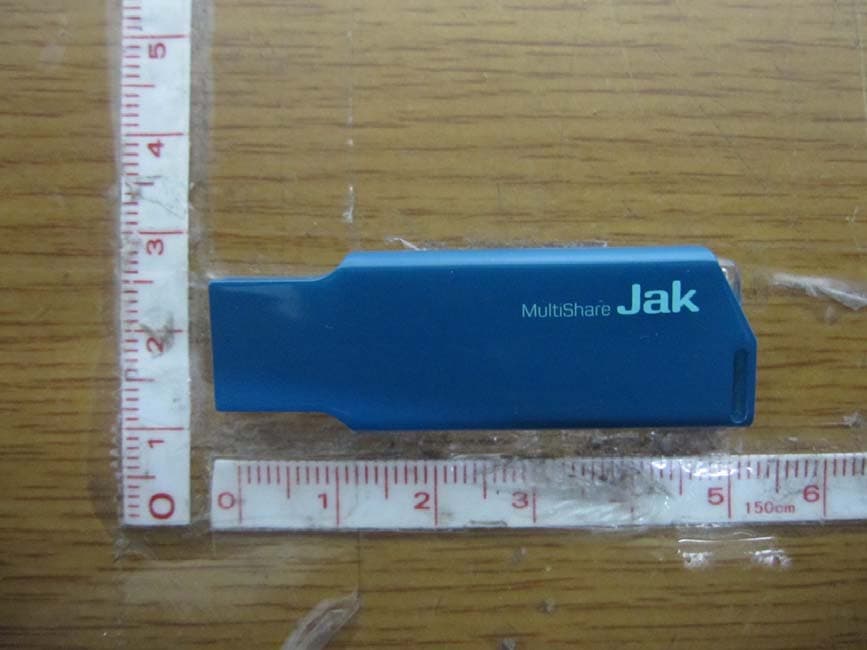
TT2JAK
Oct 31, 2012WLAN USB DONGLE
Equipment Class
DTS - Digital Transmission System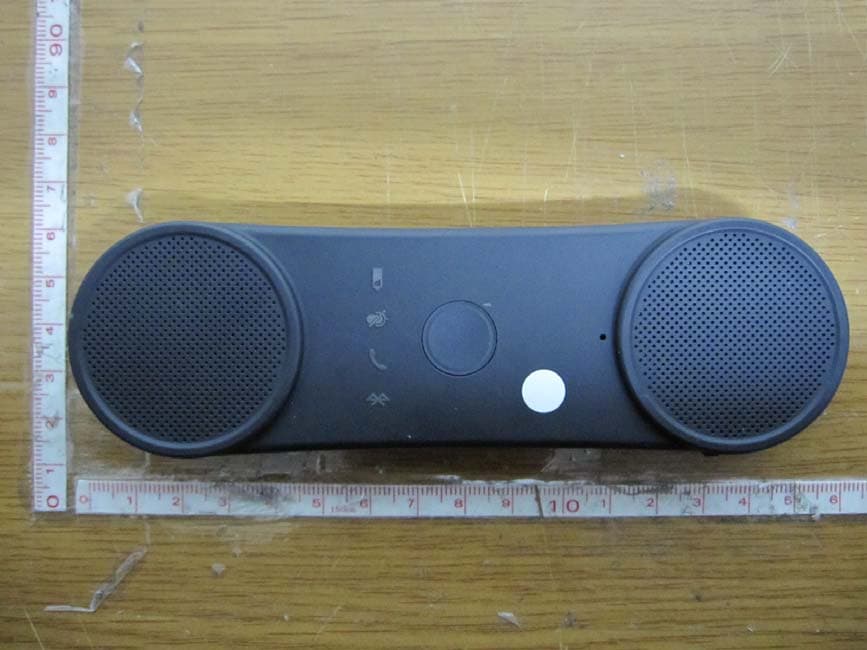
TT2BHF5000
Oct 29, 2012BLUETOOTH SPEAKERPHONE
Equipment Class
DSS - Part 15 Spread Spectrum Transmitter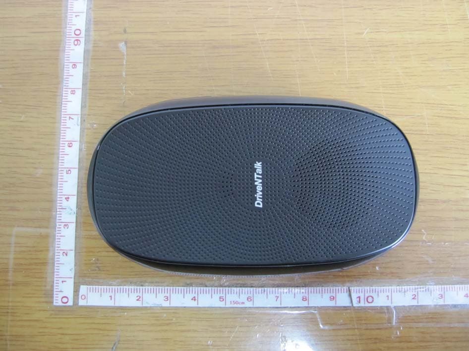
TT2BHF1800
Apr 26, 2011BLUETOOTH HANDS-FREE KIT
Equipment Class
DSS - Part 15 Spread Spectrum Transmitter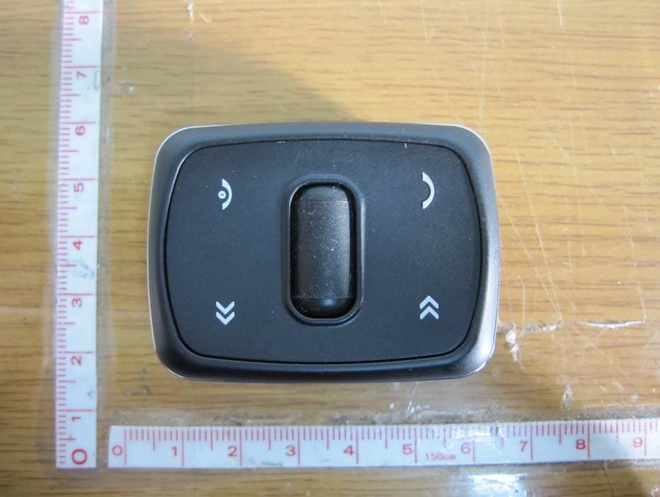
TT2KLAT8-RC
Apr 26, 2011WIRELESS REMOTE CONTROLLER
Equipment Class
DSR - Part 15 Remote Control/Security Device Transceiver