TXT41264Remote Control Transmitter
Robert Bosch Tool Corporation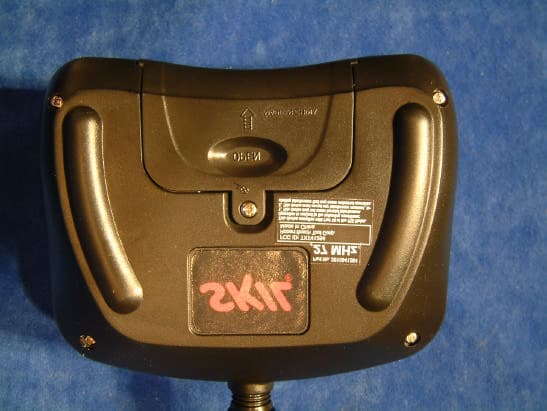
Click to zoom
Application Details
- Equipment Class
- DXX - Part 15 Low Power Communication Device Transmitter
- Date of Grant
- Feb 22, 2006
- Application Purpose
- Original Equipment
- Date of Application
- Feb 22, 2006
- Equipment Note
- Remote Control Transmitter
- Frequency Range
- 27.00000000 - 27.00000000
- Country
- United States
Documents & Files
Document Text
Text extracted from the exhibit documents filed with the FCC. Open a document above to read the original.
Users Manual
IMPORTANT:IMPORTANT :IMPORTANTE: Read Before UsingLire avant usageLeer antes de usar Operating/Safety Instructions Consignes de fonctionnement/sécurité Instrucciones de funcionamiento y seguridad For English Version Version françaiseVersión en español See page 2Voir page 9Ver la página 14 1-877-SKIL999 (1-877-754-5999) www.skil.com Call Toll Free for Consumer Information & Service Locations Pour obtenir des informations et les adresses de nos centres de service après-vente, appelez ce numéro gratuit Llame gratis para obtener información para el consumidor y ubicaciones de servicio Use only with Skil battery 120BAT or 144BAT. See instructions and warnings that came with power tool for battery care and recharging instructions. Only adults should recharge battery and install battery into car. CHOKING HAZARD - Small parts. Not for children under 3 yrs. This car is recommended for children over the age of 8 years old. Use only alkaline 9v battery in remote control unit. Do not short circuit terminals of either battery. Fire or serious injury may result. -2- Battery/Charger Before using battery charger, read all instructions and cautionary markings on (1) battery charger, (2) battery pack, and (3) product using battery. Use only the charger which accompanied your product or direct replacement as listed in the catalog or this manual. Do not substitute any other charger. Use only Skil approved chargers with your product. See Functional Description and Specifications. Donot disassemble charger or operate the charger if it has received a sharp blow, been dropped or otherwise damaged in any way. Replace damaged cord or plugs immediately. Incorrect reassembly or damage may result in electric shock or fire. Do not recharge battery in damp or wet environment. Do not expose charger to rain or snow. If battery case is cracked or otherwise damaged, do not insert into charger. Battery short or fire may result. Charge only Skil approved rechargeable batteries. See Functional Description and Specifications. Other types of batteries may burst causing personal injury and damage. Charge battery pack in temperatures above +40 degrees F (4 degrees C) and below +105 degrees F (41 degrees C). Store tool and battery pack in locations where temperatures will not exceed 120 degrees F (49 degrees C). This is important to prevent serious damage to the battery cells. Battery leakage may occur under extreme usage or temperature conditions. Avoid contact with skin and eyes. The battery liquid is caustic and could cause chemical burns to tissues. If liquid comes in contact with skin, wash quickly with soap and water, then with lemon juice or vinegar. If the liquid contacts your eyes, flush them with water for a minimum of 10 minutes and seek medical attention. Place charger on flat non-flammable surfaces and away from flammable materials when re-charging battery pack. The charger and battery pack heat during charging. Carpeting and other heat insulating surfaces block proper air circulation which may cause overheating of the charger and battery pack. If smoke or melting of the case are observed unplug the charger immediately and do not use the battery pack or charger. Use of an attachment not recommended or sold by Skil may result in a risk of fire, electric shock or injury to persons. Safety Rules Read instructions for this radio controlled car, battery and charger before operating toy. SAVE THESE INSTRUCTIONS ! WARNING -3- When batteries are not in tool or charger, keep them away from metal objects. For example, to protect terminals from shorting DO NOTplace batteries in a tool box or pocket with nails, screws, keys, etc. Fire or injury may result. To prevent fire or injury when batteries are not in tool or charger, always place protective cap onto end of battery pack. Protective cap, guards against terminal shorting. DO NOT PUT BATTERIES INTO FIRE OR EXPOSE TO HIGH HEAT. They may explode. Donotattempt to disassemble the battery or remove any component projecting from the battery terminals. Fire or injury may result. Prior to disposal, protect exposed terminals with heavy insulating tape to prevent shorting. NICKEL-CADMIUM BATTERIES If equipped with a nickel-cadmium battery, the battery must be collected, recycled or disposed of in an environmentally sound manner. “The EPA certified RBRC Battery Recycling Seal on the nickel-cadmium (Ni-Cd) battery indicates Robert Bosch Tool Corporation is voluntarily participating in an industry program to collect and recycle these batteries at the end of their useful life, when taken out of service in the United States or Canada. The RBRC program provides a convenient alterative to placing used Ni-Cd batteries into the trash or the municipal waste stream, which may be illegal in your area. Please call 1-800-8-BATTERY for information on Ni-Cd battery recycling and disposal bans/restrictions in your area, or return your batteries to a Skil/Bosch/Dremel Service Center for recycling. Robert Bosch Tool Corporation’s involvement in this program is part of our commitment to preserving our environment and conserving our natural resources.” ! WARNING ! WARNING Battery Care Battery Disposal ! WARNING Sometimes erratic behavior or loss of control of the car is the result of interference which is caused by high tension wires, high-voltage transformers, certain types of buildings, concrete walls or narrow places where radio signals can be easily affected; if you encounter this type of behavior or loss of control, change to a different locationfor playing the toy. You may encounter interference if another radio-controlled car or CB radio is operating in the vicinity on your same frequency Radio Interference FCC CAUTION: The manufacturer is not responsible for radio interference caused by unauthorized modifications to this equipment. Such modifications could void the user’s authority to operate the equipment. -4- When not in use, turn the power switch off. Remove the battery pack and the 9V battery a…
Text truncated - open the document above for the full version.
External Photos
Front Back Close-Up Back with Label
ID Label/Location Info
This device complies with Part 15 of the FCC Rules. Operation is subject to the following conditions: 1. This device may not cause harmful interference. 2. This device must accept any interference received, in- cluding interference that may cause undesired operation. FCC ID: TXT41264 Robert Bosch Tool Corp. Made in China 27 MHz Part No. 2610941264 13.00 27.00 18.16 3.25 16.82
ID Label/Location Info
Front Back Close-Up Back with Label
Operational Description
?????????? JINJIANG SUN LIN ELECTRONIC CO.LTD. ? ̄????????????????? SUN LIN INDUSTRIAL BLDG.,QIAO TOU INDUSTRIAL DISTRICT, ANHAI, JINJIANG, FUJIAN, CHINA . POST CODE 362261 TEL: (86 595)85787222, 85787008 FAX : (86 595)8578 8842 WEB-SITE: http: //www.sunlintoys.com. Email: [email protected] , [email protected] Radio Control Car Circuit Function Brief Description. CONTROLLER: The controller was supplied by 9v battery. When push the joy stick, the Integration Block “PT8A977BP” will active and generate the information code. At the same time, Q1 and CY1 will generate the 27.145MHz frequency. The information code generate by integration block “PT8A977BP” will be outputted by PIN 8. Information from PIN8 will be bridged from R1 to Q2. Then joined together with 27.145MHz frequency and finally be outputted to Q2. Q2 will process the mixing ,amplitude modulation and power amplification. The high frequency amplitude modulation will be bridged by C5,L3 and finally transmitted to the air. CAR: The car was supplied by 12V/14.4V battery. The High Frequency Resonance Circuit formed by C6?C7?C8?Q13?L1?T1 will be tuned in 27.145MHz. C5 will bridged every kind of High Hrequency Wave( wave received by the car antenna) to the High Frequency Resonance Circuit. Because the High Frequency Resonance Circuit was tuned in 27.145MHz, the other High Frequency Wave will be restrained and filtered out. Also the High Frequency Resonance Circuit will analyze the code from the high frequency wave. C11 will bridged and outputted the analyzed code into the PIN14 of the Integration Block “PT8A977BP”. Finally, the Integration Block “PT8A977BP” will process the code and analyze the function and command the Circuit to act the corresponding function. For example, if the Integration Block “PT8A977BP” analyze the code is the forward function code. It will command the Circuit to act the forward function. The Motor Drive Circuit will be responsible for all the information released by Integration Block “PT8A977BP”. The M1 will respond to forward and backward function. And M2 will respond to left and right function. The M2 Drive Circuit was supplied by power-regulated Integration Block U1. Jinjiang Sun Lin Elctronic Co.,Ltd
Parts List/Tune Up Info
TX bill of material Used Part Type Designator Footprint Description ==== ================= ========== ========== =========== 2 2.2uH L1 L2 1 3p C4 Capacitor 1 4.3V D1 1 5.6uH L3 1 9V BT1 Battery 1 10 R6 1 10K R1 1 10P C11 Capacitor 1 27.145MHz CY1 XTAL1 1 33K R2 3 47P C1 C3 C7 Capacitor 1 68P C8 1 82p C5 1 100 R3 1 103 C2 1 200K R7 1 220uF/25V C10 2 223 C6 C9 Capacitor 1 330 R4 1 390K R5 1 B S4 2 C.945 Q1 Q2 1 F S3 8 IN4148 D2 D3 D4 Diode D5 D6 D7 D8 D9 1 L S2 1 R S1 1 PT8A977BP 1 ULSK-TX PCB BOARD
Schematics
1 2 3 4 5 6 A BC D 6 5 4 3 2 1 D CB A T i t l e N um b e r R e vi s i on S i z e B D a t e : 24 - J a n- 20 06 S h e e t of F i l e : D r a w n B y : 1 2 3 4 5 6 7 1 4 1 3 1 2 1 1 1 0 9 8 S 4 B S 3 F S 1 R R 7 2 0 0 K C 9 2 2 3 C 8 6 8 P C 7 4 7 P C 1 4 7 P C 5 8 2 p C 2 1 0 3 Q 1 C .9 4 5 Q 2 C .9 4 5 R 2 3 3 K R 4 3 3 0 R 5 3 9 0 K R 3 1 0 0 R 6 1 0 R 1 1 0 K C 1 0 2 2 0 u F / 2 5 V D 1 4 .3 V C Y 1 2 7 .1 4 5 M H z L 3 5 .6 u H L 2 2 .2 u H L 1 2 .2 u H T X - 2 P T 8 A 9 7 7 B P S 2 L B T 1 9 V C 6 2 2 3 C 3 4 7 P C 4 3 p C 1 1 1 0 P D 4 I N 414 8 D 5 I N 414 8 D 3 I N 414 8 D 8 I N 414 8 D 7 I N 414 8 D 2 I N 414 8 D 9 I N 414 8 D 6 I N 414 8 TX 0 0 sunlintoys zly
Schematics
205 206 207 208
Test Report
17 January 2006 Robert Bosch Tool Corp Attn: Mr. Adrian Perry 1800 W. Central Rd Mt. Prospect, IL 60646 UL Reference: File MC1439, Project 06NK02135 Subject: EMC Test and Measurement Report for Model 2610941264 REMOTE CONTROL TRANSMITTER Dear Mr. Perry: We have provided with this letter your EMC Test Report for the above referenced model. The product was determined to comply with the requirements noted in the report. Please review the attached report and direct any questions or comments to me. We appreciate your interest in UL’s EMC Services, and encourage you to contact us in the future should you need EMC test services. This closes Project 06NK02135. Best regards, Reviewed by: Bart Mucha (Ext 41216) Jack Steiner Project Engineer Section Manager International EMC Services International EMC Services UL International EMC Services 333 Pfingsten Road Northbrook, Illinois 60062-2096 (800) 873-8536 Fax No. (847) 272-8864 http://www.ul.com/hitech/emc/ FCC ID: TXT41264 File: MC1439 Project: 06NK02135 Page 1 of 10 UL International EMC Services www.ul.com/hitech/emc (800) USE UL EMC EMC – TEST REPORT Issue Date: 17 January 2006 √ EMISSIONS IMMUNITY Test Report File No. : MC1439 Project No. : 06NK02135 Model / Type : 2610941264 Kind of Product : REMOTE CONTROL TRANSMITTER Applicant : Robert Bosch Tool Corp License Holder : Robert Bosch Tool Corp Address : 1800 W. Central Rd : Mt. Prospect, IL 60646 : Manufacturer : Same as Applicant : : : Test Result : COMPLIANT This report without appendices consists of 10 pages. Appendix A contains test photos, and Appendix B contains original test data. The data contained in this report reflects only the items tested in the configurations and mode of operations described. An attempt has been made to arrange the EUT, with the equipment provided, into a test configuration which maximizes the observed emissions of the EUT while simulating, as close as practical, a typical end-use installation. Underwriters Laboratories Inc. authorizes the above company to reproduce this report provided it is reproduced in its entirety. Underwriters Laboratories Inc. 333 Pfingsten Rd. Northbrook, IL 60062 Fax: (847) 272-8864 FCC ID: TXT41264 File: MC1439 Project: 06NK02135 Page 2 of 10 UL International EMC Services www.ul.com/hitech/emc (800) USE UL EMC REPORT DIRECTORY SECTION TITLE GENERAL 1.0 General Product Description 1.1 Model Differences 1.2 Environmental Conditions in Test Lab 1.3 Calibration Details of Equipment Used for Measurement 1.4 EUT (Equipment Under Test) Configuration 1.5 EUT Operating Mode 1.6 Device Modifications EMISSIONS 2.0 Emissions Test Regulations Fundamental Frequency Radiated Electric Field Emissions Spurious Radiated Electric Field Emissions Occupied Bandwidth Measurement IMMUNITY 3.0 Immunity Test Regulations CONCLUSION 4.0 General Remarks 4.1 Summary APPENDICIES A Test Setups (Photos, Diagrams and Drawings) B Test Data FCC ID: TXT41264 File: MC1439 Project: 06NK02135 Page 3 of 10 UL International EMC Services www.ul.com/hitech/emc (800) USE UL EMC 1.0 GENERAL PRODUCT DESCRIPTION The Equipment Under Test (EUT) was a 27.12MHz transmitter used for remote controlling of a toy car. 1.0.1 Equipment Mobility: Portable 1.0.2 Test Voltage and Frequency: Voltage (V) Frequency (Hz) 9V DC 1.1 MODEL DIFFERENCES Any other model(s) represented by the models tested in this investigation will be documented by the manufacturer. 1.2 ENVIRONMENTAL CONDITIONS IN TEST LAB Temperature: 20-25 °C Relative Humidity: 30-60% RH Atmospheric Pressure: 860-1060 mbar 1.3 CALIBRATION OF EQUIPMENT USED FOR MEASUREMENT All test equipment and test accessories are calibrated on a regular basis. The maximum time between calibrations is one year or what is recommended by the manufacturer, whichever is less. All test equipment calibrations are traceable to the National Institute of Standards and Technology (NIST), therefore, all test data recorded in this report is traceable to NIST. FCC ID: TXT41264 File: MC1439 Project: 06NK02135 Page 4 of 10 UL International EMC Services www.ul.com/hitech/emc (800) USE UL EMC 1.4 EUT CONFIGURATION(s) See Appendix A for individual set-up configuration(s). In addition to the EUT, the following peripheral devices and/or cables were connected during the measurement: Device Manufacturer Model FCC ID EUT Bosch 2610941264 TXT41264 Cable Manufacturer Length Type Shield Type Shield Termination None 1.5 EUT OPERATING MODE(s) The equipment under test was operated during the measurements under the following conditions: Continuously Transmitting 1.6 DEVICE MODIFICATIONS The following modifications were necessary for compliance: No modifications were required. FCC ID: TXT41264 File: MC1439 Project: 06NK02135 Page 5 of 10 UL International EMC Services www.ul.com/hitech/emc (800) USE UL EMC 2.0 EMISSIONS TEST REGULATIONS Emissions testing was performed according to the following regulations: 47 CFR Part 15 Subpart C: 2005 + ANSI C63.4 - 2000 47 CFR Part 15.227 47 CFR Part 15.35 47 CFR Part 15.209 FCC ID: TXT41264 File: MC1439 Project: 06NK02135 Page 6 of 10 UL International EMC Services www.ul.com/hitech/emc (800) USE UL EMC FUNDAMENTAL FREQUENCY RADIATED ELECTRIC FIELD EMISSIONS Test Location 10 Meter Semi-Anechoic Chamber Test Instruments Instrument Serial Number EMC Number Last Cal Next Cal HP Spectrum Analyzer - EMC4085 06JAN2006 06JAN2007 HP QP Adapter - EMC4016 06JAN2006 06JAN2007 EMCO 1089 Loop Antenna 6502/1 EMC4026 09JAN2006 09JAN2007 Frequency Range of Measurement 20MHz – 30MHz Measurement Distance 3 meters Test Results The requirements are: MET Remarks • Bandwidths used for measurements: RBW=9kHz VBW=10kHz • All pre-scans and final measurements were conducted by scanning the unit 360° around. • Pre-scans with the loop antenna were conducted in both Horizontal and Vertical Polarization. • The pre-scans were conducted with the transmitter placed in three axis and for final measurement the worst case axis were measured. See Appendix B for complete test results. …
Text truncated - open the document above for the full version.
Test Setup Photos
FCC ID: TXT41264 File: MC1439 Project: 06NK02135 Page A2 of A2 UL International EMC Services www.ul.com/hitech/emc (800) USE UL EMC Radiated Emissions Transmitter Location X-Axis Radiated Emissions Y-Axis Radiated Emissions Z-Axis
Contact Information
Applicant
Josh Macy
Technical Contact
Robert Bosch Tool CorporationAdrian Perry
224-232-2968
1800 W. Central Road · Mount Prospect, Illinois · United States
Non-Technical Contact
Robert Bosch Tool CorporationAdrian Perry
224-232-2968
Test Firm
UL LLCRick Titus
Technical Specifications
| # | Rule Parts | Frequency Range | Power Output |
|---|---|---|---|
| 1 | 15C | 27 MHz - 27 MHz | - |
Other Applications from Robert Bosch Tool Corporation
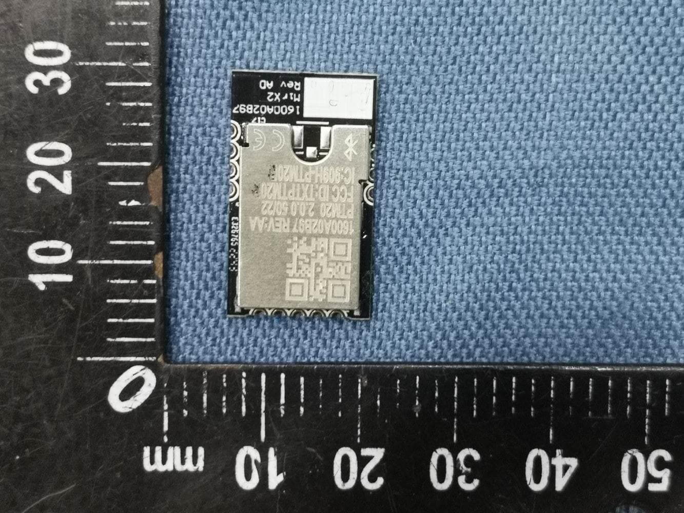
TXTPTM20
Jul 24, 2023MirX2 Bluetooth Module
Equipment Class
DTS - Digital Transmission System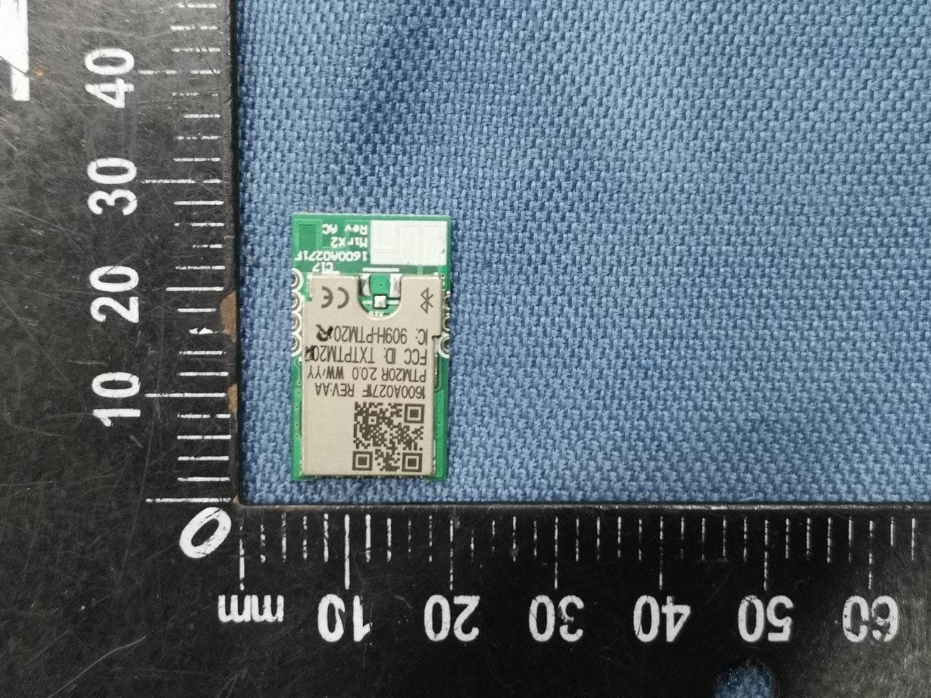
TXTPTM20R
Jul 24, 2023MirX2 Bluetooth Module
Equipment Class
DTS - Digital Transmission System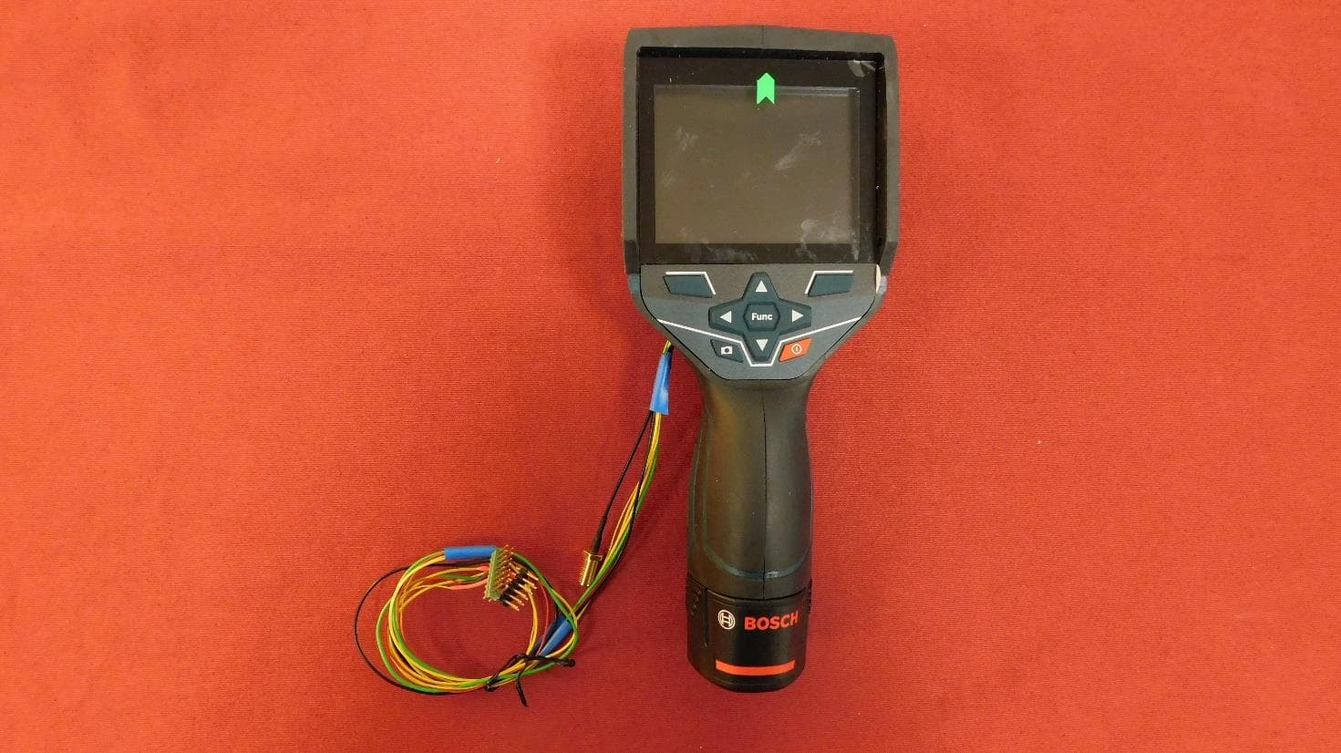
TXTGTC400C
Jul 10, 2022Thermal Camera
Equipment Class
DTS - Digital Transmission System
TXTGCY300-42
Aug 11, 2021Connectivity Module
Equipment Class
DTS - Digital Transmission System
TXTGLM1652XX
Oct 13, 2020Laser Rangefinder
Equipment Class
DTS - Digital Transmission System