TXTPB360CPower Box
Robert Bosch Tool Corporation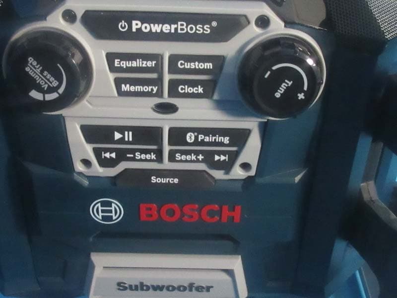
Click to zoom
Application Details
- Equipment Class
- DSS - Part 15 Spread Spectrum Transmitter
- Date of Grant
- Jul 08, 2015
- Application Purpose
- Original Equipment
- Date of Application
- Jul 08, 2015
- Equipment Note
- Power Box
- Frequency Range
- 2402.00000000 - 2480.00000000
- Country
- United States
Documents & Files
Document Text
Text extracted from the exhibit documents filed with the FCC. Open a document above to read the original.
Users Manual
For English Version Version française Versión en español See page 2 Voir page 14 Ver la página 26 Operating/Safety Instructions Consignes de fonctionnement/sécurité Instrucciones de funcionamiento y seguridad IMPORTANT: IMPORTANT : IMPORTANTE: Read Before Using Lire avant usage Leer antes de usar 1-877-BOSCH99 (1-877-267-2499) www.boschtools.com Call Toll Free for Consumer Information & Service Locations Pour obtenir des informations et les adresses de nos centres de service après-vente, appelez ce numéro gratuit Llame gratis para obtener información para el consumidor y ubicaciones de servicio PB360C PB360C-C 2 IMPORTANT SAFETY INSTRUCTIONS WARNING - TO PREVENT FIRE OR SHOCK HAZARD, DO NOT USE THIS PLUG WITH AN EXTENSION CORD, RECEPTACLE OR OTHER OUTLET UNLESS THE BLADES CAN BE FULLY INSERTED TO PREVENT BLADE EXPOSURE. - TO PREVENT FIRE OR SHOCK HAZARD, DO NOT EXPOSE THE APPLIANCE TO RAIN OR MOISTURE. CAUTION: TO REDUCE THE RISK OF ELECTRIC SHOCK, DO NOT REMOVE COVER (OR BACK). NO USER SERVICEABLE PARTS INSIDE. REFER SERVICING TO QUALIFIED SERVICE PERSONNEL. The lighting flash with arrowhead symbol within an equilateral triangle is intended to alert the user to the presence of uninsulated “dangerous voltage” within the product’s enclosure that may be of sufficient magnitude to constitute a risk of electric to persons. The exclamation point within an e quilateral triangle is intended to alert the user to the presence of important operating and maintenance (servicing) instructions in the literature accompanying the product. 1) Read these instructions. 2) Keep these instructions. 3) Heed all warnings. 4) Follow all instructions. 5) Do not use this apparatus near water. 6) Clean only with dry cloth. 7) Do not block any ventilation openings. Install in accordance with the manufacturer’s instructions. 8) Do not install near any heat sources such as radiators, heat registers, stoves, or other apparatus (including amplifiers) that produce heat. 9) Do not defeat the safety purpose of the polarized or grounding-type plug. A polarized plug has two blades with one wider than the other. A grounding type plug has two blades and a third grounding prong. The wide blade or the third prong are provided for your safety. If the provided plug does not fit into your outlet, consult an electrician for replacement of the obsolete outlet. 10) Protect the power cord from being walked on or pinched particularly at plugs, convenience receptacles, and the point where they exit from the apparatus. 11) Only use attachments/accessories specified by the manufacturer. 12) Use only with the cart, stand, tripod, bracket, or table specified by the manufacturer, or sold with the apparatus. When a cart is used, use caution when moving the cart/apparatus combination to avoid injury from tip-over. 13) Unplug this apparatus during lightning storms or when unused for long periods of time. 14) Refer all servicing to qualified service personnel. Servicing is required when the apparatus has been damaged in any way, such as power-supply cord or plug is damaged, liquid has been spilled or objects have fallen into the apparatus, the apparatus has been exposed to rain or moisture, does not operate normally, or has been dropped. 15) The mains plug is used as the disconnect device, the disconnect device shall remain readily operable. 16) Read the rating label on the bottom of the unit for power input and other safety information. Apparatus shall not be exposed to dripping or splashing water and that no object filled with liquids such as vases shall be placed on the apparatus. Warning: To reduce risk of electric shock, only plug the unit into a Ground fault circuit interrupter (GFCI) protected outlet when used in damp locations. if a GFCI protected outlet is not available, use a portable receptacle with built-in GFCI protection. 3 Table of Contents Safety..........................................................................2-3 Important Safety Instructions.....................................2 Table of Contents.........................................................3 FCC/IC Information.....................................................3 Battery/Charger..........................................................4 Battery Care................................................................4 Battery Disposal.........................................................4 Functional Description and Specifications...............5 LCD Displays..............................................................6 Setting the Clock........................................................6 PB360C & PB360C-C Controls.................................7 Operating Instructions..............................................8-9 Audio Settings.............................................................8 Radio Function...........................................................8 Aux Function...............................................................8 Bluetooth Pairing Function.........................................9 USB Charging.............................................................9 Releasing and Inserting the Battery Pack............... 10 Charging the Battery Pack.......................................10 Important Charging Notes........................................11 To Power the Unit.......................................................11 Use of the Convenient 4-way Outlets..................... 11 Changing Clock Batteries.........................................12 Trouble Shooting........................................................12 Maintenance ...............................................................13 Accessories.................................................................13 FCC Statement This device complies with FCC radiation exposure limits set forth for an uncontrolled environment. This device complies with Part 15 of the FCC Rules. Operation is subject to the following two conditions: (1) this device may not cause harmful in…
Text truncated - open the document above for the full version.
Cover Letter(s)
CERTIFICATE OF COMPLIANCE Authorized under Declaration of Conformity according to 47 CFR, Part 2 and Part 15 of the FCC Rules. The product listed in follows was (were) tested in the BTL EMC Laboratory to comply with the criteria limits Class B of conducted and radiated emissions of the Technical Standards FCC Part 15, Subpart B, established by the FCC, USA. Equipment Power Box Model Name PB360C Brand Name BOSCH Applicant Robert Bosch Tool Corporation Address 1800 West Central Road, Mount Prosect, Illinois, 60056 United States Standard(s) FCC Part 15, Subpart B: 2014 ANSI C63.4-2014 Report(s) BTL-FICE-1-1507C050 The test data, data evaluation, and equipment configuration contained in our test report(s) above was(were) obtained utilizing the test procedures, test instruments, test sites that has been accredited by the Authority of TAF according to the ISO-17025 quality assessment standard and technical standard(s). The test data contained in the referenced test report relate only to the EUT sample and item(s) tested. Andy Chiu Authorized Signatory BTL INC. B1, No. 37, Lane 365, Yang-Guang St., Nei-Hu District, Taipei City 114, Taiwan. TEL:+886-2-2657-3299 FAX:+886-2-2657-3331
External Photos
Project No.: 1507C050 Page 2 of 8 Project No.: 1507C050 Page 3 of 8 Project No.: 1507C050 Page 4 of 8
ID Label/Location Info
-- C B A D E F C B D E 4 3 2 5 6 7 8 4 3 2 1 5 6 7 8 A F 1 1107 © Robert Bosch Tool Corporation. Alle Rechte vorbehalten, auch bzgl.jeder Verfuegung, Verwertung, Reproduktion, Bearbeitung,Weitergabe sowie für den Fall von Schutzrechtsanmeldungen. © Robert Bosch Tool Corporation. All rights reserved, also regardingany disposal, exploitation, reproduction, editing, distribution,as well as in the event of applications for industrial property rights. Treatment/ Behandlung 1/1 Ind.Change/Aend. YYYYMMDD Drawn/Gez. Checked/Gepr. Releas./Freig. BWN Resp. dept./Verantw. Abt. Add. info./Zus. Info. Size/Gst. Missed details/Fehlende Angaben Mat./Stoff From/Aus Repl. for Doc.type Sheet/Bl. Ind. DP/TD Repl. by Format MNR -- Scale/M.stab Mat.meets/Stoffe s Crit. P. Lang./Spr. Wght./Gew. Syst. en/de A3 N2580-1AI DRW tol. principle/ Tol.-grundsatz ISO 8015:1985-12 all linear dimensions in/ Alle Laengenmasse in mm ± 0.1 non-toleranced dimensions/ Nicht tolerierte Masse angles, dimension of the shorter side / Winkel, Laenge des kuerzeren Schenkels non-tol.broken edges/ Nicht tol.gebrochene Kanten ± 0.1± 0.2± 0.3± 0.5± 0.8 ± 0.2± 0.5± 1 ± 1°± 30 ’± 20 ’± 10 ’± 5 ’ to / bis 10 > 10 ...50 > 50 ...120 > 120 ...400 > 400 0,5 ...3 > 3 ...6 > 6 ...30 > 30 ...120 > 120 ...400 > 400 ...1000 MATERIAL - 2 MIL POLYESTER BASE WITH 3 MIL MATTE CLEAR POLYESTER LAMINATE. COPY TO BE SUBSURFACE PRINTED. ADHESIVE SUITABLE FOR ADHERING TO NYLON POLYCARBONATE OR ABS PLASTICS. MATERIAL & SUPPLIER TO BE UL & CSA RECOGNIZED. APPLICABLE STANDARDS - 2610928230. NOTES: PT/ESS1-NA 1:1 AA6035A? 2015 M.MOKEYEV ? ? 511 NAMEPLATE ? AA Riesgo de descargas eléctricas. No abra el cargador. Para un funcionamiento con seguridad, ver el manual. Reemplace inmediatamente el cordón dañado con un cordón de calibre 14 AWG SJTW que tenga capacidad de resistencia al agua. No exponer a lluvia o humedad. Enchufe la unidad en un tomacorriente protegido con un interruptor GFCI cuando se utilice en lugares húmedos. Cargar unicamente baterias BOSCH BAT600-BAT620. Otras baterías podrían reventar, causando lesiones y daños. Risque de choc électrique – ne pas ouvrir. Pour un fonctionnement sur, reportezvous au manuel. En cas d’en dommagement du cordon, le remplacer immédiatement par un cordon de calibre 14 AWG SJTW classi é comme hydrorésistant. Ne pas exposer à la pluie ou à 'humidité. Branchez le dispositif dans une prise de courant protégée par un disjoncteur de fuite à la terre quand vous l'utilisez dans un endroit humide. Chargez uniquement BOSCH piles BAT600-BAT620. D'autres batteries risqueraient d'éclater et de causer des blessures et des dommages. Risk of electric shock - do not open. For safe operation see manual. Replace damaged cord immediately with 14 AWG SJTW cord with water resistant rating. Do not expose to rain or moisture. Plug the unit into a GFCI protected outlet when used in damp locations.Charge only BOSCH batteries BAT600-BAT620. Other batteries may burst causing injury and damage. WARNING AVERTISSEMENT PB360C 0601429A10 INPUT: 120 VAC ~ 60 Hz 12 A OUTLETS: AC: 120 V~ 60 Hz 10A CHARGER: OUTPUT: 14.4 - 18 V 0.9 A INPUT: 120 VAC ~ 60 Hz 0.25 A LISTED AUDIO PRODUCT 28GZ E255378 2C3 This device complies with Part 15 of the FCC Rules. Operation is subject to the following conditions: 1. This device may not cause harmful interference. 2. This device must accept any interference received, including interference that may cause undesired operation. FCC ID: TXTPB360C CAUTION RISK OF ELECTRIC SHOCK DO NOT OPEN SN ADVERTENCIA Robert Bosch Tool Corp., Mount Prospect, IL Made in China PMS 1505 ORANGE AND PMS 427 GRAY COPY ON BLACK BACKGROUND MANUFACTURED: BC 202.00 202.00 Label location Back view
Internal Photos
Project No.: 1507C050 Page 5 of 8 Project No.: 1507C050 Page 6 of 8 Project No.: 1507C050 Page 7 of 8 Project No.: 1507C050 Page 8 of 8
RF Exposure Info
FCC RF EXPOSURE REPORT FCC ID: TXTPB360C Project No. : 1507C050 Equipment : Power Box Model : PB360C Applicant : Robert Bosch Tool Corporation Address : 1800 West Central Road, Mount Prosect, Illinois, United States 60056 According: : FCC Guidelines for Human Exposure IEEE C95.1 BTL INC. No.3, Jinshagang 1st Road, Shixia, Dalang Town, Dongguan, China. TEL: +86-769-8318-3000 FAX: +86-769-8319-6000 Table for Filed Antenna Ant. Brand Model NameAntenna TypeConnector Gain(dBi) 1 N/A AN-BT001-ID50PCB N/A -2.09 GENERAL CONCULUSION: Maximum measured transmitter power: OutputPower (dBm) Output Power (mW) Limit (mW) 6.26 4.23 10 According to FCC KDB447498 V05, Appendix A, SAR Test Exclusion Thresholds for 100 MHz – 6 GHz and ≤ 50 mm The maximum measured output peak power of this EUT is 4.23mW, less than 10mW at 5mm distance. Conclusion: No SAR evaluation required since transmitter power is below FCC threshold
Test Report
Report No.: BTL-FICP-1-1507C050 Page 1 of 11 6 FCC&IC Radio Test Report FCC ID: TXTPB360C IC: 909H-PB360C-C This report concerns (check one): Original Grant Class II Change Project No. : 1507C050 Equipment : Power Box Model Name for FCC : PB360C Model Name for IC : PB360C-C Applicant : Robert Bosch Tool Corporation Address : 1800 West Central Road, Mount Prosect, Illinois, 60056 United States Date of Receipt : Jul. 02, 2015 Date of Test : Jul. 02, 2015 ~ Jul. 07, 2015 Issued Date : Jul. 08, 2015 Tested by : BTL Inc. Testing Engineer : (David Mao) Technical Manager : (Leo Hung) Authorized Signatory : (Steven Lu) BTL INC. No.3, Jinshagang 1st Road, Shixia, Dalang Town, Dongguan, Guangdong, China. TEL: +86-769-8318-3000 FAX: +86-769-8319-6000 Report No.: BTL-FICP-1-1507C050 Page 2 of 11 6 Declaration BTL represents to the client that testing is done in accordance with standard procedures as applicable and that test instruments used has been calibrated with the standards traceable to National Measurement Laboratory (NML) of CHINA, or National Institute of Standards and Technology (NIST) of U.S.A. BTL's reports apply only to the specific samples tested under conditions. It is manufacture’s responsibility to ensure that additional production units of this model are manufactured with the identical electrical and mechanical components. BTL shall have no liability for any declarations, inferences or generalizations drawn by the client or others from BTL issued reports. BTL’s report must not be used by the client to claim product certification, approval, or endorsement b y NVLAP, NIST, or any agency of the Federal Government. This report is the confidential property of the client. As a mutual protection to the clients, the public and BTL-self, extracts from the test report shall not be reproduced except in full with BTL’s authorized written approval. BTL’s laboratory quality assurance procedures are in compliance with the ISO Guide 17025 requirements, and accredited by the conformity assessment authorities listed in this test report. Limitation For the use of the authority's logo is limited unless the Test Standard(s)/Scope(s)/Item(s) mentioned in this test report is (are) included in the conformity assessment authorities acceptance respective. Report No.: BTL-FICP-1-1507C050 Page 3 of 11 6 Table of Contents Page 1 . CERTIFICATION 7 2 . SUMMARY OF TEST RESULTS 8 2.1 TEST FACILITY 9 2.2 MEASUREMENT UNCERTAINTY 9 3 . GENERAL INFORMATION 10 3.1 GENERAL DESCRIPTION OF EUT 10 3.2 DESCRIPTION OF TEST MODES 12 3.3 TABLE OF PARAMETERS OF TEXT SOFTWARE SETTING 12 3.4 BLOCK DIAGRAM SHOWING THE CONFIGURATION OF SYSTEM TESTED 13 3.5 DESCRIPTION OF SUPPORT UNITS 14 4 . EMC EMISSION TEST 15 4.1 CONDUCTED EMISSION MEASUREMENT 15 4.1.1 POWER LINE CONDUCTED EMISSION LIMITS 15 4.1.2 TEST PROCEDURE 15 4.1.3 DEVIATION FROM TEST STANDARD 15 4.1.4 TEST SETUP 16 4.1.5 EUT OPERATING CONDITIONS 16 4.1.6 EUT TEST CONDITIONS 16 4.1.7 TEST RESULTS 16 4.2 RADIATED EMISSION MEASUREMENT 17 4.2.1 RADIATED EMISSION LIMITS 17 4.2.2 TEST PROCEDURE 18 4.2.3 DEVIATION FROM TEST STANDARD 18 4.2.4 TEST SETUP 19 4.2.5 EUT OPERATING CONDITIONS 20 4.2.6 EUT TEST CONDITIONS 20 4.2.7 TEST RESULTS (9KHZ TO 30MHZ) 20 4.2.8 TEST RESULTS (BETWEEN 30MHZ TO 1000 MHZ) 21 4.2.9 TEST RESULTS (ABOVE 1000 MHZ) 21 5 . NUMBER OF HOPPING CHANNEL 22 5.1 APPLIED PROCEDURES 22 5.1.1 TEST PROCEDURE 22 5.1.2 DEVIATION FROM STANDARD 22 5.1.3 TEST SETUP 22 5.1.4 EUT OPERATION CONDITIONS 22 5.1.5 EUT TEST CONDITIONS 22 5.1.6 TEST RESULTS 22 Report No.: BTL-FICP-1-1507C050 Page 4 of 11 6 Table of Contents Page 6 . AVERAGE TIME OF OCCUPANCY 23 6.1 APPLIED PROCEDURES / LIMIT 23 6.1.1 TEST PROCEDURE 23 6.1.2 DEVIATION FROM STANDARD 23 6.1.3 TEST SETUP 23 6.1.4 EUT OPERATION CONDITIONS 24 6.1.5 EUT TEST CONDITIONS 24 6.1.6 TEST RESULTS 24 7 . HOPPING CHANNEL SEPARATION MEASUREMENT 25 7.1 APPLIED PROCEDURES / LIMIT 25 7.1.1 TEST PROCEDURE 25 7.1.2 DEVIATION FROM STANDARD 25 7.1.3 TEST SETUP 25 7.1.4 EUT TEST CONDITIONS 25 7.1.5 TEST RESULTS 25 8 . BANDWIDTH TEST 26 8.1 APPLIED PROCEDURES 26 8.1.1 TEST PROCEDURE 26 8.1.2 DEVIATION FROM STANDARD 26 8.1.3 TEST SETUP 26 8.1.4 EUT OPERATION CONDITIONS 26 8.1.5 EUT TEST CONDITIONS 26 8.1.6 TEST RESULTS 26 9 . PEAK OUTPUT POWER TEST 27 9.1 APPLIED PROCEDURES / LIMIT 27 9.1.1 TEST PROCEDURE 27 9.1.2 DEVIATION FROM STANDARD 27 9.1.3 TEST SETUP 27 9.1.4 EUT OPERATION CONDITIONS 27 9.1.5 EUT TEST CONDITIONS 27 9.1.6 TEST RESULTS 27 10 . ANTENNA CONDUCTED SPURIOUS EMISSION 28 10.1 APPLIED PROCEDURES / LIMIT 28 10.1.1 TEST PROCEDURE 28 10.1.2 DEVIATION FROM STANDARD 28 10.1.3 TEST SETUP 28 10.1.4 EUT OPERATION CONDITIONS 28 10.1.5 EUT TEST CONDITIONS 28 10.1.6 TEST RESULTS 28 11 . MEASUREMENT INSTRUMENTS LIST 29 Report No.: BTL-FICP-1-1507C050 Page 5 of 11 6 Table of Contents Page 12 . EUT TEST PHOTO 31 ATTACHMENT A - CONDUCTED EMISSION 35 ATTACHMENT B - RADIATED EMISSION (9KHZ-30MHZ) 38 ATTACHMENT C - RADIATED EMISSION (30MHZ TO 1000MHZ) 40 ATTACHMENT D - RADIATED EMISSION (ABOVE 1000MHZ) 53 ATTACHMENT E - NUMBER OF HOPPING CHANNEL 78 ATTACHMENT F - AVERAGE TIME OF OCCUPANCY 80 ATTACHMENT G - HOPPING CHANNEL SEPARATION MEASUREMENT 93 ATTACHMENT H - BANDWIDTH 98 ATTACHMENT I - PEAK OUTPUT POWER 103 ATTACHMENT J - ANTENNA CONDUCTED SPURIOUS EMISSION 108 Report No.: BTL-FICP-1-1507C050 Page 6 of 11 6 REPORT ISSUED HISTORY Issued No. Description Issued Date BTL-FICP-1-1507C050 Original Issue. Jul. 08, 2015 Report No.: BTL-FICP-1-1507C050 Page 7 of 11 6 1. CERTIFICATION Equipment : Power Box Brand Name : BOSCH Model Name for FCC : PB360C Model Name for IC : PB360C-C Applicant Robert Bosch Tool Corporation Manufacturer : Robert Bosch Tool Corporation Address : 1800 West Central Road, Mount Prosect, Illinois, 60056 United States Factory : Shenzhen Synchron Electronics Co., Ltd. Address : No. 9 Mei Li Road, Xia Mei Lin, Fu Tian Area, Shenzhen, Guangdong, China Date of Test : Jul. 02, 2015 ~ Jul. 07, 2015 Test Sample : ENGINEERING SAMPLE …
Text truncated - open the document above for the full version.
Test Setup Photos
Report No.: BTL-FICP-1-1507C050 Page 31 of 11 6 12. EUT TEST PHOTO Conducted Measurement Photos Report No.: BTL-FICP-1-1507C050 Page 32 of 11 6 Radiated Measurement Photos 9KHz to 30MHz Report No.: BTL-FICP-1-1507C050 Page 33 of 11 6 Radiated Measurement Photos 30MHz to 1000MHz Report No.: BTL-FICP-1-1507C050 Page 34 of 11 6 Radiated Measurement Photos Above 1000MHz
Contact Information
Applicant
Josh Macy
Technical Contact
Non-Technical Contact
BTL Inc.Cathy Wang
[email protected]86-769-83183000
Test Firm
BTL Inc.Daisy Dai
Technical Specifications
| # | Rule Parts | Frequency Range | Power Output |
|---|---|---|---|
| 1 | 15C | 2.40 GHz - 2.48 GHz | 4.00 mW |
Other Applications from Robert Bosch Tool Corporation
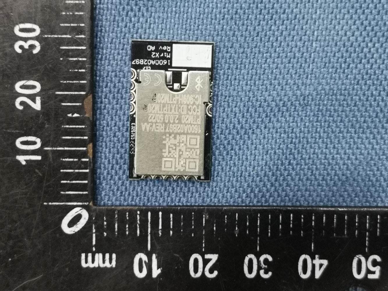
TXTPTM20
Jul 24, 2023MirX2 Bluetooth Module
Equipment Class
DTS - Digital Transmission System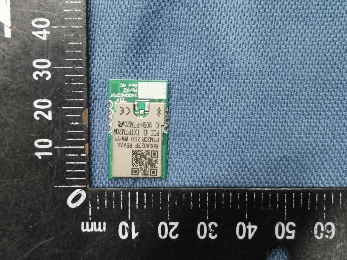
TXTPTM20R
Jul 24, 2023MirX2 Bluetooth Module
Equipment Class
DTS - Digital Transmission System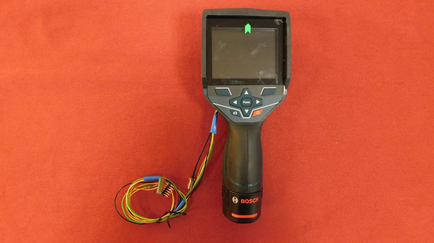
TXTGTC400C
Jul 10, 2022Thermal Camera
Equipment Class
DTS - Digital Transmission System
TXTGCY300-42
Aug 11, 2021Connectivity Module
Equipment Class
DTS - Digital Transmission System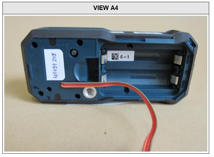
TXTGLM1652XX
Oct 13, 2020Laser Rangefinder
Equipment Class
DTS - Digital Transmission System