TYLKP2Wireless Keypad
Scientech Electronics Co., Ltd.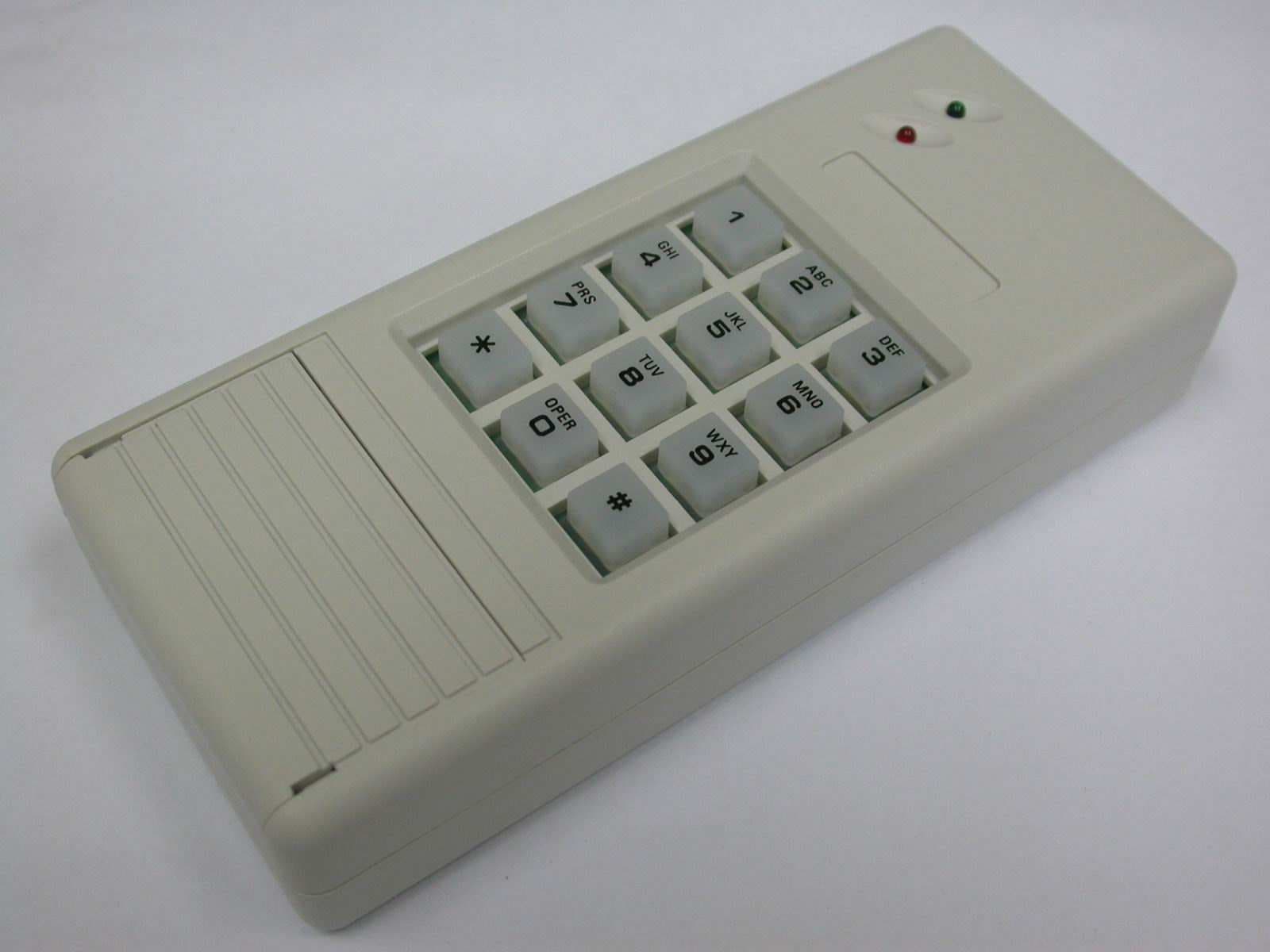
Click to zoom
Application Details
- Equipment Class
- DSC - Part 15 Security/Remote Control Transmitter
- Date of Grant
- Jan 31, 2006
- Application Purpose
- Original Equipment
- Date of Application
- Jan 31, 2006
- Equipment Note
- Wireless Keypad
- Frequency Range
- 433.92000000 - 433.92000000
- Country
- Taiwan
Documents & Files
Document Text
Text extracted from the exhibit documents filed with the FCC. Open a document above to read the original.
Users Manual
ACCESSORIES The LS-30 system includes a full range of accessories, so you can customize many feature of your security system. All the radio transmitters used in the LS-30 system, except the Remote Controller, have a unique random code that is set by the factory with 16,777,216 combinations in total. Also with specially designed transmission timing control, the LS-30 system can effectively prevent mutual interference from other transmitters in the system. The Remote Controller uses copy-preventing hopping-code technology, changing its radio code every time you press the button. The combinations possible through this hopping-code are up to 7.3 X 10 19 . To comply with the regulations in most countries, radio power is limited to below 10mW, and effective range is about 100 meters measured at open field. The range may be somewhat less indoors, depending on the layout of building construction and furniture. You may enroll all the wireless accessories and change their related settings, either through the guidance of the interactive LCD display on the Base Unit explained in the “INSTALLATION” section that follows, or by using a computer with the proprietary software “HyperSecureLink” through an interface adapter, which offers a quicker and simpler way to perform the installation in. NOTE: The changes or modifications not expressly approved by the party responsible for compliance could void the user’s authority to operate the equipment. The comply with the FCC RF exposure compliance requirements, this device and its antenna must not be co-located or operating to conjunction with any other antenna or transmitter. This device complies with Part 15 of the FCC Rules. Operation is subject to the following two conditions: (1) this device may not cause harmful interference, and (2) this device must accept any interference received, including interference that may cause undesired operation. WIRELESS KEYPAD KP-2S INTRODUCTION The KP-2S is the wireless keypad for the LS-30; it controls the Base Unit remotely. With its backlight feature, you can operate it even in the dark. Its 4-digit password will prevent unauthorized use. INSTALLATION 1. Remove the battery hatch of the KP-2S, insert four AAA alkaline batteries and replace the battery hatch. 2. Refer to next page ”CHANGE PASSWORD”, and change the factory password on the KP-2S as below. A) Enter default password 9999 (factory setting), and the green LED will light. B) Press * for 3 seconds then release. C) Enter your new password. 3. Enroll the KP-2S as a controller on the Base Unit Select “Installer Mode” on the Base Unit, and enter Installer Password to gain access authority. Then select \Set Device\Enroll Device\Controller\Zone No. to enroll the ID of KP-2S by pressing “password, 3” on the KP-2S. You may change its various attributes under \Set Device\Change Device Setting\Controller, to fulfill different requirements. Remarks: If theKP-2S is set with Latchkey attribute ON, the Base Unit will call “Latchkey Number” (refer to Section 3-2-1) whenever the Disarm or Away signal is sent from this KP-2S. 4. Choose mounting location A) Choose a convenient location like on the doorjamb or on the wall adjacent to the door. Note: Your wireless keypad should be mounted out of the reach of children. B) Drill one 3/16 inch (4.7mm) pilot hole 1 inch deep for top screw. Insert screw into pilot hole, leaving the head of the screw exposed about 1/8 inch from the wall. Slide the unit over the exposed screw so that it hangs on the wall. Remove the battery hatch and batteries to the expose second mounting hole. Mark the location of the pilot hole then remove KP-2S. Drill a 3/16 inch pilot hole 1 inch deep. Replace keypad and insert screw. C) Replace the batteries and the battery hatch. LED Indication Green LED: It lights up when a correct password is entered. It flashes when radio signal is transmitting. Red LED: It flashes when a key is pressed. If the correct password is not entered within 20 keystrokes, RED LED will flash for 3 seconds, then the KP-2S will lock up for 5 minutes. Back-light LED: Pressing any key will cause the back-light LED to light up and stay on for 10 seconds from the last keystroke. It flashes with every keystroke when low battery is detected. OPERATION You can control the LS-30 remotely as shown, by entering the 4-digit password followed by a specific key. : ARM : DISARM : HOME The KP-2S also provides a “Panic” transmission, when the start and hash keys are pressed simultaneously . No password is needed for this operation : PANIC * # + ABC 2 4-digit password ABC 2 DEF 3 GHI 4 Notes: Before you use KP-2S to control the system remotely, you have to program a proper Exit/Entry Delay Time on the Base Unit. Change Password Note: 1. When you change your password, you have to delete the old RF transmission code on LS-30 first, then re- register it. 2. The Installer should teach users how to change the password, so they can change it when necessary. Tampering Protection If the correct password is not entered within 20 keystrokes, the KP-2S will lock up for 5 minutes. All LEDs will remain off during this period, and all keystrokes are ignored to prevent unauthorized tampering. In addition, a radio signal of “tamper” will be sent if the battery hatch is opened. This will trigger the siren if the system is disarmed, or the siren and auto-dialer, if the system is armed. Remarks: 1.The tamper signal can be re-triggered after 40 seconds, if the battery hatch is opened again. 2.The tamper function can be enabled or disabled under \Installer Mode\Set Siren menu on LS-30 Base Unit. Low Battery Detection When weak battery is detected, the backlit LED will flash with every keystrokes. If the correct password is entered, the green LED will light. The KP-2S will work about 20 times after low battery is detected. * Green LED lights Press 3 seconds then release new password new password once again Green LED off when key pressedGreen LED flashes for 3 seconds Battery Rep…
Text truncated - open the document above for the full version.
Cover Letter(s)
FCC ID: TYLKP2 Device Name: Wireless Keypad Model No.: KP-2S Date: 2005/12/12 Compliance Certification Services Certification Division 561F Monterey Road Morgan Hill, CA 95037 To whom it may concern: We, the undersigned, hereby authorize ELECTRONICS TESTING CENTER, TAIWAN, to act on our behalf in all manners relating to application for equipment authorization, including signing of all documents relating to these matters. Any and all acts carried out by ELECTRONICS TESTING CENTER, TAIWAN on our behalf shall have the same effect as acts of our own. In authorizing ELECTRONICS TESTING CENTER, TAIWAN as our agent, we still recognize that we are responsible to: a)comply with the relevant provisions of the certification program; b)make all necessary arrangements for the conduct of the evaluation, including provision for examining documentation and access to all areas, records (including internal audit reports) and personnel for the purposes of evaluation (e.g. testing, inspection, assessment, surveillance, reassessment) and resolution of complaints; c)make claims regarding certification only in respect of the scope for which certification has been granted; d)do not use our product certification in such a manner as to bring the Certification Division into disrepute and not make any statement regarding our product certification which the Certification Division may consider misleading or unauthorized; e)upon suspension or cancellation of certification, discontinue use of all advertising matter that contains any reference thereto and return any certification documents as required by the Certification Division; f)use certification only to indicate the products are certified as being in conformity with specified standards; g)endeavor to ensure that no certificate or report nor any part thereof is used in a misleading manner; h) ensure that any reference to our product certification in communication media such as documents, brochures or advertising, complies with the requirements of the Certification Division; i) keep a record of all complaints made known to the us relating to the product compliance with requirements of the relevant standard and to make these records available to the Certification Division when requested; j) take appropriate action with respect to such complaints and any deficiencies found in products or services that affect compliance with the requirements for certification; k) document the actions taken. This authorization is valid until further written notice from the applicant. Sincerely Yours, By:By: Kevin Wang (Signature)(Printed) Title:Marketing Manager Applicant:Scientech Electronics Co., Ltd. Address:4F, No. 501-17. Chung-Cheng Rd., Hsin-Tien City, Taipei 231, Taiwan, R.O.C. Tel:886-2-22183085 Fax:886-2-22187380
Cover Letter(s)
FCC ID: TYLKP2 Federal Communications Commission Dear Sir: Pursuant to Section 0.457 and 0.459 of the Commission’s Rules, the Applicant hereby requests confidential treatment of information accompanying this Application as outlined below: Schematics Block Diagram Operational Descriptions The above materials contain trade secrets and proprietary information not customarily released to the public. The public disclosure of these matters might be harmful to the Applicant and provide unjustified benefits to its competitors. The Applicant understands that pursuant to Rule 0.457, disclosure of this Application and all accompanying documentation will not be made before the date of the Grant for this application. By:By: Kevin Wang (Signature)(Printed) Title:Marketing Manager Applicant: Scientech Electronics Co., Ltd. Address:4F, No. 501-17. Chung-Cheng Rd., Hsin-Tien City, Taipei 231, Taiwan, R.O.C. Tel:886-2-22183085 Fax:886-2-22187380
External Photos
ETC Report No.: ET94S-09-165-06 Page A1 of A1 FCC ID.:TYLKP2 ANNEX A: EXTERNAL CONSTRUCTION PHOTOS OF EUT 1. Outside view 1 of EUT 2. Outside view 2 of EUT
ID Label/Location Info
KP-2S 36mm 22mm Model: KP-2S FCC ID: TYL KP2 This device complies with Part 15 of the FCC Rules. Operation is subject to the following two conditions: (1) this device may not cause harmful interference, and (2) this device must accept any interference received, including interference that may cause undesired operation.
Internal Photos
ETC Report No.: ET94S-09-165-06 Page B1 of B2 FCC ID.: TYLKP2 ANNEX B: INTERNAL CONSTRUCTION PHOTOS OF EUT 1. Inside View of EUT 2. Front view of PCB ETC Report No.: ET94S-09-165-06 Page B2 of B2 FCC ID.: TYLKP2 3. Rear view of PCB
Test Report
ETC Report No. : ET94S-09-165-06 Sheet 1 of 21 Sheets FCC ID.: TYLKP2 Rev. No 1.0 CONFORMANCE TEST REPORT FOR FCC 47 CFR, Part 15 Subpart C Report No.: ET94S-09-165-06 Client: Scientech Electronics Co., Ltd. Product: Wireless Keypad Model: KP-2S FCC ID: TYLKP2 Manufacturer/supplier: Scientech Electronics Co., Ltd. Date test item received: 2005/09/20 Date test campaign completed: 2005/10/31 Date of issue: 2005/11/22 The test result only corresponds to the tested sample. It is not permitted to copy this report, in part or in full, without the permission of the test laboratory. Total number of pages of this test report: 21 pages Total number of pages of photos: External photos 1 pages Internal photos 2 pages Setup photos 2 pages Test Engineer Checked By Approved By James Mark Joe Hsieh ELECTRONICS TESTING CENTER, TAIWAN NO.8, LANE 29, WENMING RD., LESHAN TSUEN, GUISHAN SHIANG, TAOYUAN COUNTY, TAIWAN 33383, R.O.C. TEL: (03) 3276170~4 INT: +886-3-3276170~4 FAX: (03) 3276188 INT: +886-3-3276188 ETC Report No. : ET94S-09-165-06 Sheet 2 of 21 Sheets FCC ID.: TYLKP2 Rev. No 1.0 Client : Scientech Electronics Co., Ltd. Address : 4F, No. 501-17, Chung-Cheng Rd., Hsin-Tien City, Taipei 231, Taiwan, R.O.C. Manufacturer : Scientech Electronics Co., Ltd. Address : 4F, No. 501-17, Chung-Cheng Rd., Hsin-Tien City, Taipei 231, Taiwan, R.O.C. EUT : Wireless Keypad Trade name : LifeSOS Model No. : KP-2S Comment issues : (1) The report also apply to model: KP-2 (2) The multiple listing recognized without test basis is according to information supplied by manufacturer. A detail documentation of the above models must be verified by legal right organization for the EMC characteristic with relation to the subject model. Power Source : 6VDC Regulations applied : FCC 47 CFR, Part 15 Subpart C (2005) The testing described in this report has been carried out to the best of our knowledge and ability, and our responsibility is limited to the exercise of reasonable care. This certification is not intended to believe the sellers from their legal and/or contractual obligations. The compliance test is only certified for the test equipment and the results of the testing report relate only to the item tested. The compliance test of this report was conducted in accordance with the appropriate standards. It’s not intention to assure the quality and performance of the product. This report shall not be reproduced except in full, without the approval of ETC. This report must not be used by the client to claim product endorsement by NVLAP or any agency of the U.S. Government. Laboratory Introduction: Electronics Testing Center, Taiwan is recognized, filed and mutual recognition arrangement as following: 1 ISO9001: TüV Product Service 2 ISO/IEC 17025: BSMI, CNLA, DGT, NVLAP, CCIBLAC, UL, Compliance 3 Filing: FCC, Industry Canada, VCCI 4 MRA: Australia, Hong Kong, New Zealand, Singapore, USA, Japan, Korea, China, APLAC through CNLA 5 FCC Registration Number: 90588, 91094, 91095 NVLAP Lab Code 200133-0 ETC Report No. : ET94S-09-165-06 Sheet 3 of 21 Sheets FCC ID.: TYLKP2 Rev. No 1.0 Table of Contents Page 1. GENERAL INFORMATION ......................................................................................................................................4 1.1 PRODUCT DESCRIPTION.................................................................................................................................................4 1.2 CHARACTERISTICS OF DEVICE:......................................................................................................................................4 1.3 TEST METHODOLOGY....................................................................................................................................................4 1.4 TEST FACILITY...............................................................................................................................................................4 2. DEFINITION AND LIMITS........................................................................................................................................5 2.1 DEFINITION....................................................................................................................................................................5 2.2 RESTRICTED BANDS OF OPERATION...............................................................................................................................5 2.3 LIMITATION....................................................................................................................................................................6 2.4 LABELING REQUIREMENT..............................................................................................................................................7 2.5 USER INFORMATION.......................................................................................................................................................7 3. RADIATED EMISSION MEASUREMENT..............................................................................................................8 3.1 APPLICABLE STANDARD.................................................................................................................................................8 3.2 MEASUREMENT PROCEDURE.........................................................................................................................................8 3.3 TEST DATA..................................................................................................................................................................10 3.4 FIELD STRENGTH CALCULATION..................................................................................................................................12 3.5 RADIATED TEST EQUIPMENT.......................................................................................................................................12 3.6 MEASURING INSTRUMENT SETUP.…
Text truncated - open the document above for the full version.
Test Setup Photos
ETC Report No.:ET94S-09-165-06 Sheet 1 of 2 Sheets FCC ID.: TYLKP2 Radiated Measurement Photos x-axis ETC Report No.:ET94S-09-165-06 Sheet 2 of 2 Sheets FCC ID.: TYLKP2 y-axis z-axis
Contact Information
Applicant
Kevin Wang(Marketing Manager)
Test Firm
Electronics Testing Center, TaiwanWin-Po Tsai
Technical Specifications
| # | Rule Parts | Frequency Range | Power Output |
|---|---|---|---|
| 1 | 15.231 | 433.92 MHz - 433.92 MHz | - |
Other Applications from Scientech Electronics Co., Ltd.
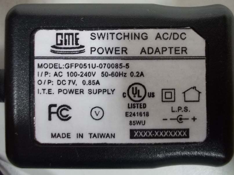
TYLLS10
Aug 07, 2014Home Management Gateway
Equipment Class
DSC - Part 15 Security/Remote Control Transmitter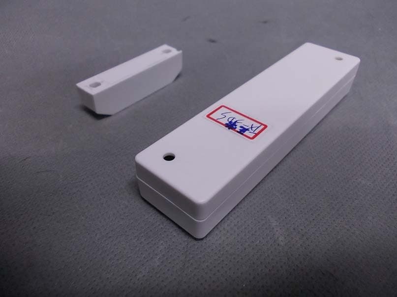
TYLTX3N
Aug 21, 2013Electronic Sensor
Equipment Class
DXX - Part 15 Low Power Communication Device Transmitter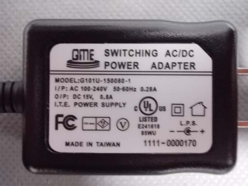
TYLLS30N
Aug 19, 2013Alarm Base Unit
Equipment Class
DSC - Part 15 Security/Remote Control Transmitter
TYLWS3N
Aug 07, 2013Outdoor Siren
Equipment Class
DXX - Part 15 Low Power Communication Device Transmitter
TYLIR2N
Jul 24, 2013Motion Detector
Equipment Class
DXX - Part 15 Low Power Communication Device Transmitter