U6XF2ITE01Hearing Aid (in the ear)
Bernafon AG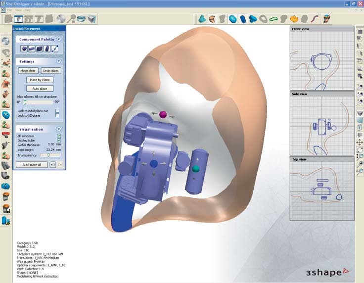
Click to zoom
Application Details
- Equipment Class
- DXX - Part 15 Low Power Communication Device Transmitter
- Date of Grant
- Apr 09, 2013
- Application Purpose
- Original Equipment
- Date of Application
- Apr 09, 2013
- Equipment Note
- Hearing Aid (in the ear)
- Frequency Range
- 3.84000000 - 3.84000000
- Company
- Bernafon AG
- Country
- Switzerland
Documents & Files
Document Text
Text extracted from the exhibit documents filed with the FCC. Open a document above to read the original.
Users Manual
ACRIVA 9 ACRIVA 7 In-the-ear hearing instruments INSTRUCTIONS FOR USE 2 3 TABLE OF CONTENTS General Warnings and Safety Guidelines 7 Introduction 12 Description of Features 13 Inserting Instruments 15 Removing Instruments 16 Operating Your Instruments (ON/OFF) 17 Changing the Volume Level 18 Changing Programs 21 Muting 22 Telecoil Function 23 Telephone Use 24 Changing the Battery 26 Data Logging and Learning 28 Operating the Hearing Instruments with the Optional RC-P Remote Control 29 Operating the Hearing Instruments with the Optional SoundGate Communication Device 30 Instrument Care 32 4 5 Cleaning the Sound Outlet 33 Microphone Protection System 36 Using Your Hearing Instruments 39 Tips for Communicating with Hearing Impaired People 43 Your Hearing Instrument Configuration 45 Accessories 48 Environmental Protection 49 Product Approval, Markings and Compliance 50 Cell Phone and Hearing Instrument Compatibility 52 International Warranty 54 Common Problems and Solutions 56 Information for the Hearing Care Professional 62 Compliance with Requirements for Europe 64 Compliance with Radio Communications Requirements for the USA and Canada 66 Information and Explanation of Symbols 68 Service 70 6 Congratulations on the purchase of your new Bernafon hearing instruments. The amplification of sound provided by your hearing instruments was adjusted by your hearing care professional to the needs of your individual hearing loss. With a little practice, you will soon be on your way to better hearing. Please read the entire contents of this booklet before using your hearing instruments. It contains instructions and important information about the use and handling of your hearing instruments and batteries. 7 General Warnings and Safety Guidelines Hearing instruments and batteries can be dangerous if swallowed or improperly used. Such actions can result in severe injury, permanent hearing loss or even fatality. Familiarize yourself completely with the following general warnings before using your hearing instru- ments. Hazard Warnings Never allow others to wear your hearing instruments, because they are adjusted for your hearing requirements and may permanently damage another person’s hearing. A slap to your ear while wearing the instrument could be harmful. Avoid wear- ing your hearing instrument while playing contact sports (e.g. rugby, football etc.). 8 Hearing instruments, their parts and batteries should be kept out of reach of infants, children and anyone who might swallow these items or otherwise cause themselves injury. Discard batteries and keep them out of sight of infants, small children, persons of mental incapacity or pets. Clean your hearing instruments and their parts on a regular basis as recommended. Micro-organ isms from unclean instruments may cause skin irritations. Be careful with leaking battery liquid, as it is a hazardous substance. Never try to recharge non-rechargeable batteries. Never change the battery or adjust the controls of the hearing instrument in front of infants, small children and persons of mental incapacity. 9 Never put your hearing instrument or batteries in your mouth, they could easily be swallowed. Keep batteries away from medications. Batteries are easily mistaken for pills. In case a battery or hearing instrument is swallowed, see a doctor immediately. Be aware of the possibility that your instruments may stop functioning without notice. Keep this in mind while you circulate in traffic or otherwise depend on warning sounds. Traffic or other warning sounds may also be reduced in level by a directional micro- phone when these sounds are coming from behind you. Remove your instruments before applying aftershave, hairspray, oils, perfume, mosquito repellent, lotions, etc. Allow the product to dry before wearing your instruments. 10 Safety Information ·Hearing instruments should be used only as directed and adjusted by your trained hearing care professional. Misuse or improper adjust- ments can result in sudden and permanent hearing loss. ·Hearing instruments will not restore normal hearing or prevent hearing loss resulting from organic conditions. ·Be aware that use of a hearing instrument may cause excess earwax to build up in the ear canal which may require removal by a trained medical professional. ·In rare cases, a hearing instrument or earmold may cause a discharge from the ear or allergic reaction. See a physician immediately if these conditions occur. ·An earmold is a custom-made product. If you experience discomfort or irritation of your ear, please see your hearing care professional immediately for modification of the earmold. ·Never insert cleaning tools into the sound outlet or microphone inlet. This could damage the hearing instruments. 11 ·Do not expose hearing instruments to extreme heat by leaving them in the car, near a radiator, etc. ·Avoid exposing your instruments to water and moisture i.e. steambaths, showers, heavy rain, etc. ·Never attempt to dry your instruments with a hair dryer, microwave oven, etc. ·It is recommended to remove your hearing instruments before sleeping. ·Protect your instruments by keeping them in the case when you are not wearing them. 12 AR_ILLU_IIC_BW 5 Introduction AR_ILLU_ITED_BW 10 AR_ILLU_ITCPD_BW 7 AR_ILLU_ITCD_BW 8 In-the-ear hearing instruments vary in size and shape due to the unique characteristics of individual ears. AR_ILLU_ITC_BW 6 AR_ILLU_CICP_BW 2 The following instruments are covered in these instructions: Acriva In-the-Ear Hearing Instruments AR9 ITED AR9 ITCPD AR9 ITCD AR7 ITED AR7 ITCPD AR7 ITCD AR9 ITC AR9 CICP/CIC AR9 IIC AR7 ITC AR7 CICP/CIC 13 Description of Features 1 Vent 2 Canal 3 Sound outlet with wax protection 4 Microphone opening with O-cap filter 5 Battery door 6 Push button (optional) 7 Volume control (optional) AR_ILLU_ITED_BW 10 4 ITED 5 1 2 AR_ILLU_ITCPD_BW 7 6 4 ITCPD/ITCD 3 2 AR_ILLU_ITC_BW 6 4 7 ITC 1 3 4 6 1 4 5 6 3 2 5 14 1 Vent 2 Canal 3 Sound outlet with wax protection 4 Micropho…
Text truncated - open the document above for the full version.
Users Manual
ITCD, ITC, ITCP, ITED, CIC & CICP, IIC PRECISO 9 PRECISO 7 Instructions for use In-the-ear hearing instruments 2 3 TABLE OF CONTENTS General Warnings and Safety Guidelines 7 Introduction 12 Description of Features 13 Inserting Instruments 15 Removing Instruments 16 Operating Your Instruments (ON/OFF) 17 Changing the Volume Level 18 Changing Programs 21 Muting 22 Telecoil Function 23 Telephone Use 24 Changing the Battery 26 Data Logging and Learning 28 Operating the Hearing Instruments with the Optional RC-P Remote Control 29 Operating the Hearing Instruments with the Optional SoundGate Communication Device 30 Instrument Care 32 4 5 Cleaning the Sound Outlet 33 Microphone Protection System 36 Using Your Hearing Instruments 39 Tips for Communicating with Hearing Impaired People 43 Your Hearing Instrument Configuration 45 Accessories 48 Environmental Protection 49 Product Approval, Markings and Compliance 50 Cell Phone and Hearing Instrument Compatibility 52 Warranty 54 Common Problems and Solutions 56 Information for the Hearing Care Professional 62 Compliance with Requirements for Europe 64 Compliance with Radio Communications Requirements for the USA and Canada 66 Information and Explanation of Symbols 68 Service 70 6 Congratulations on the purchase of your new Hidden Hearing hearing instruments. The amplifica- tion of sound provided by your hearing instruments was adjusted by your hearing care professional to the needs of your individual hearing loss. With a little practice, you will soon be on your way to better hearing. Please read the entire contents of this booklet before using your hearing instruments. It contains instructions and important information about the use and handling of your hearing instruments and batteries. 7 General Warnings and Safety Guidelines Hearing instruments and batteries can be dangerous if swallowed or improperly used. Such actions can result in severe injury, permanent hearing loss or even fatality. Familiarize yourself completely with the following general warnings before using your hearing instru- ments. Hazard Warnings Never allow others to wear your hearing instruments, because they are adjusted for your hearing requirements and may permanently damage another person’s hearing. A slap to your ear while wearing the instrument could be harmful. Avoid wear- ing your hearing instrument while playing contact sports (e.g. rugby, football etc.). 8 Hearing instruments, their parts and batteries should be kept out of reach of infants, children and anyone who might swallow these items or otherwise cause themselves injury. Discard batteries and keep them out of sight of infants, small children, persons of mental incapacity or pets. Clean your hearing instruments and their parts on a regular basis as recommended. Micro-organ isms from unclean instruments may cause skin irritations. Be careful with leaking battery liquid, as it is a hazardous substance. Never try to recharge non-rechargeable batteries. Never change the battery or adjust the controls of the hearing instrument in front of infants, small children and persons of mental incapacity. 9 Never put your hearing instrument or batteries in your mouth, they could easily be swallowed. Keep batteries away from medications. Batteries are easily mistaken for pills. In case a battery or hearing instrument is swallowed, see a doctor immediately. Be aware of the possibility that your instruments may stop functioning without notice. Keep this in mind while you circulate in traffic or otherwise depend on warning sounds. Traffic or other warning sounds may also be reduced in level by a directional micro- phone when these sounds are coming from behind you. Remove your instruments before applying aftershave, hairspray, oils, perfume, mosquito repellent, lotions, etc. Allow the product to dry before wearing your instruments. 10 Safety Information ·Hearing instruments should be used only as directed and adjusted by your trained hearing care professional. Misuse or improper adjust- ments can result in sudden and permanent hearing loss. ·Hearing instruments will not restore normal hearing or prevent hearing loss resulting from organic conditions. ·Be aware that use of a hearing instrument may cause excess earwax to build up in the ear canal which may require removal by a trained medical professional. ·In rare cases, a hearing instrument or earmold may cause a discharge from the ear or allergic reaction. See a physician immediately if these conditions occur. ·An earmold is a custom-made product. If you experience discomfort or irritation of your ear, please see your hearing care professional immediately for modification of the earmold. ·Never insert cleaning tools into the sound outlet or microphone inlet. This could damage the hearing instruments. 11 ·Do not expose hearing instruments to extreme heat by leaving them in the car, near a radiator, etc. ·Avoid exposing your instruments to water and moisture i.e. steambaths, showers, heavy rain, etc. ·Never attempt to dry your instruments with a hair dryer, microwave oven, etc. ·It is recommended to remove your hearing instruments before sleeping. ·Protect your instruments by keeping them in the case when you are not wearing them. 12 AR_ILLU_IIC_BW 5 Introduction AR_ILLU_ITED_BW 10 AR_ILLU_ITCPD_BW 7 AR_ILLU_ITCD_BW 8 In-the-ear hearing instruments vary in size and shape due to the unique characteristics of individual ears. AR_ILLU_ITC_BW 6 AR_ILLU_CICP_BW 2 The following instruments are covered in these instructions: Preciso In-the-Ear Hearing Instruments PC9 ITED PC9 ITCPD PC9 ITCD PC7 ITED PC7 ITCPD PC7 ITCD PC9 ITC PC9 CICP/CIC PC9 IIC PC7 ITC PC7 CICP/CIC 13 Description of Features 1 Vent 2 Canal 3 Sound outlet with wax protection 4 Microphone opening with O-cap filter 5 Battery door 6 Push button (optional) 7 Volume control (optional) AR_ILLU_ITED_BW 10 4 ITED 5 1 2 AR_ILLU_ITCPD_BW 7 6 4 ITCPD/ITCD 3 2 AR_ILLU_ITC_BW 6 4 7 ITC 1 3 4 6 1 4 5 6 3 2 5 14 1 Vent 2 Canal 3 Sound o…
Text truncated - open the document above for the full version.
External Photos
INTRODUCTION PROGRAM LOCAL PRODUCTION ACRIVA 9|7 Preliminary ACRIVA 9|7 • INTRODUCTION PROGRAM 131646 • 03.2013 • Rev. 00-D • Service & Production Support • Bernafon AG • Switzerland Page 2 of 41 TABLE OF CONTENTS FOR ACRIVA 9|7 Table of contents for Acriva 9|7 ...................................................................................................................... 2 Acriva 9|7 Product family ................................................................................................................................ 3 Acriva 9|7 Kits ...............................................................................................................................................4-5 Acriva 9|7 Production & Service documentation overview .......................................................................... 6 Kit preparation of Acriva styles ................................................................................................................... 7-9 Programming ............................................................................................................................................ 10-11 Serial number laser marking ........................................................................................................................ 12 Serial number label marking ........................................................................................................................ 13 Serial number labels ..................................................................................................................................... 13 Acriva 9|7 kits ................................................................................................................................................. 14 Tools ............................................................................................................................................................... 15 Modeling – Placement of RECEIVER – support plane ................................................................................. 16 Modeling – Placement of RECEIVER ............................................................................................................ 17 modeling – Placement of receiver – horizontal ........................................................................................... 18 Modeling – Placement of Receiver – Vertical ............................................................................................... 19 Modeling – Measuring the receiver tube length ....................................................................................20-21 Modeling – Prowax ...................................................................................................................................22-23 Modeling – Check placement of receiver and support ............................................................................... 24 Modeling – Placement of telecoil ................................................................................................................. 25 Assembly – Red Protection Lacquer............................................................................................................. 26 Assembly – Conformal Coating on amplifi er .............................................................................................. 26 Assembly – Glue Amplifi er to faceplate ....................................................................................................... 27 Assembly – Receiver #58 .............................................................................................................................. 28 Assembly SLA – Receiver #58 ...................................................................................................................... 29 Assembly UV – Measuring the rec. tube length .......................................................................................... 30 Assembly – Telecoil ........................................................................................................................................ 31 Assembly UV – Measuring the rec. tube length ......................................................................................... 32 Assembly – Placing Litz Wires in the instrument ........................................................................................ 33 Assembly – Placing litz wires in WL instrument .......................................................................................... 34 Assembly – Protection cover (Only for fl oating amp)................................................................................. 35 Placement of T-cap fi lter *) ...................................................................................................................................................................................................................... 36 Removal of T-cap fi lter * ) .............................................................................................................................. 36 Assembly – Placement of O-Cap fi lter ......................................................................................................... 37 Assembly – Removal of O-Cap fi lter ............................................................................................................ 37 Pull-out string ............................................................................................................................................38-39 Assembly – Preparing and Placement of ProWax ....................................................................................... 40 Wireless Range test ....................................................................................................................................... 41 ACRIVA 9|7 • INTRODUCTION PROGRAM 131646 • 03.2013 • Rev. 00-D • Service & Production Support • Bernafon AG • Switzerland Page 3 of 41 ACRIVA 9|7 PRODUCT FAMILY Introd…
Text truncated - open the document above for the full version.
ID Label/Location Info
Close, glue & finish S L A & U V t e c h n oLo g y • I t e P r o d cU t I o n S e rV Ic e & P r o dU c tI o n S U P Po r t • b e r nA f o n A g • S wI t z e rL An d wo r k I nS t rU c tI o n Page 2 of 22 c Lo S e , gL Ue & fI n I Sh wo r k I nS t rU c tI o n • I t e P r o dU c tI o n • S L A & U V t e c h n oL o g y 100045 • 07.2010 • reV. 01 • S e r V I c e & P r o d U c t I o n S U P P o r t • b e r n A f o n A g • S w I t z e r L A n d Table of contents common materials for close, glue & finish ............................................................................ Page 3 Laser serial number production............................................................................................. Page 4 closing – faceplate Solution ................................................................................................. Page 6 closing – carrier Solution ..................................................................................................... Page 8 ITC D how to place electronic......................................................................................................... Page 9 closing – Unit Solution ......................................................................................................... Page 11 CIC/MC final control after closing the instrument ............................................................................... Page 13 direct instrument ................................................................................................................. Page 14 faceplate cut ........................................................................................................................ Page 15 Vent position ........................................................................................................................ Page 16 buff and polish ..................................................................................................................... Page 17 Lacquer ................................................................................................................................ Page 18 Pull out string ....................................................................................................................... Page 19 high knob ............................................................................................................................ Page 20 Microphone protection grid .................................................................................................. Page 21 replacement of microophone wind screen on Itc................................................................... Page 22 Page 3 of 22 c Lo S e , gL Ue & fI n I Sh wo r k I nS t rU c tI o n • I t e P r o dU c tI o n • S L A & U V t e c h n oL o g y 100045 • 07.2010 • reV. 01 • S e r V I c e & P r o d U c t I o n S U P P o r t • b e r n A f o n A g • S w I t z e r L A n d Common materials for Close, glue & finish DescriptionCode no glue, Loctite 420 (20 gr.)794-30-035-06 clamps 890-21-019-01 faceplate cutter, spiral890-20-142-09 tape, transparent890-03-058-01 optic fiber set, complete (220V) 890-21-517-04 Pre-cut tape, 10 battery size (100 pcs.)775-20-300-10 Pre-cut tape, 312 battery size (100 pcs.) 775-20-301-11 Miller, cylindrical890-20-042-08 Miller, conical820-15-036-03 Miller, conical (small)890-20-125-08 holder for sandpaper890-21-317-02 Sandpaper, grit 120, width 15 mm, brown890-20-136-01 Sandpaper, grit 180, width 15 mm, green890-20-154-04 buffing mops890-03-026-02 Polishing mops890-03-027-03 wax Pumice 949, for first buffing788-90-006-05 wax Atol 6, for second buffing788-90-005-04 transparent test tool refer to the style specific code no. on the Introduc- tion Program burr 1.0 mm890-20-031-05 Acrylic modelling paste, red (20 gr.)780-30-092-07 Acrylic modelling paste, blue (20 gr.)780-30-093-08 Acrylic emodelling paste Xpress beige (20 gr.)780-30-097-00 Pull out string890-01-501-04 drill 1.4 mm890-20-113-04 drill, long spiral, 0.6 mm890-20-143-00 drill, short spiral, 0.6 mm890-20-127-00 brush for lacquering825-18-097-04 Lacquer, hard coat, LP/h, 100 ml795-10-008-04 Lacquer, hard coat, Sonopal A1, 100 ml795-10-010-08 Lacquer, soft coat, LP/w, 100 ml795-10-009-05 Label, red dot (500 pieces)586-01-067-04 Label, blue dot (500 pieces)586-01-902-05 Label, white dot (500 pieces)586-01-068-05 tray, white, disposable (250 pieces)890-01-148-05 depth gauge refer to the Product specific Spare Parts List “f oam” suspension, receiver (250 pieces)540-97-063-05 Motor890-21-313-08 high knob for volume control refer to the Product specific Spare parts list Protection grid for microphone (100 pieces)890-01-230-00 Page 4 of 22 c Lo S e , gL Ue & fI n I Sh wo r k I nS t rU c tI o n • I t e P r o dU c tI o n • S L A & U V t e c h n oL o g y 100045 • 07.2010 • reV. 01 • S e r V I c e & P r o d U c t I o n S U P P o r t • b e r n A f o n A g • S w I t z e r L A n d laser serial number production 1. Load logo file in the laser machine. If the laser software for automatic generation of the serial number is installed, then scan bar code for order number. 2. to obtain the best result, laser mark on a flat surface of the shell. 3. Place the shell into the fixture. be sure that the shell is correctly secured in the fixture otherwise the marking will not be readable. 4. close the laser machine drawer/door. Scan the necessary bar code(s) on the work order with the bar code laser. 5. Press “Start write” button on the laser machine. the laser marking will automatcally take place. 6. when the marking is done remove the shell from the fixture. flat surface Page 5 of 22 c Lo S e , gL Ue & fI n I Sh wo r k I nS t rU c tI o n • I t e P r o dU c tI o n • S L A & U V t e c h n oL o g y 100045 • 07.2010 • reV. 01 • S e r V I c e & P r o d U c t I o n S U P P o r t • b e r n A f o n A g • S w I t z e r L A n d 9. check that the serial number, model and company name on the work order corresponds to the shell marking. 10. check for cor…
Text truncated - open the document above for the full version.
Internal Photos
Test report no.: 1-4852/12-01-02-A 2012-11-12 Page 31 of 35 Annex C Internal photographs of the EUT Photo documentation: Photo 1: Photo 2: Test report no.: 1-4852/12-01-02-A 2012-11-12 Page 32 of 35 Photo 3: Photo 4: Test report no.: 1-4852/12-01-02-A 2012-11-12 Page 33 of 35 Photo 5: Photo 6:
Test Report
2012-12-12 Page 1 of 24 TEST REPORT Test report no.: 1-4852/12-01-02-A Testing laboratory Applicant CETECOM ICT Services GmbH Untertuerkheimer Strasse 6 – 10 66117 Saarbruecken / Germany Phone: + 49 681 5 98 - 0 Fax: + 49 681 5 98 - 9075 Internet: http://www.cetecom.com e-mail: [email protected] Accredited Testing Laboratory: The testing laboratory (area of testing) is accredited according to DIN EN ISO/IEC 17025 (2005) by the Deutsche Akkreditierungsstelle GmbH (DAkkS) The accreditation is valid for the scope of testing procedures as stated in the accreditation certificate with the registration number: D-PL-12076-01-01 Area of Testing: Radio/Satellite Communications Oticon A/S Kongebakken 9 2765 Smørum / DENMARK Phone: +45 39 17 71 00 Fax: -/- Contact: Jørgen Peter Hanuscheck e-mail: [email protected] Phone: +45 39 13 85 38 Manufacturer Oticon A/S Kongebakken 9 2765 Smørum / DENMARK Test standard/s 47 CFR Part 15 Title 47 of the Code of Federal Regulations; Chapter I Part 15 - Radio frequency devices RSS - 210 Issue 8 Spectrum Management and Telecommunications - Radio Standards Specification Low-power Licence-exempt Radiocommunication Devices (All Frequency Bands): Category I Equipment RSS - Gen Issue 3 General Requirements and Information for the Certification of Radiocommunication Equipment For further applied test standards please refer to section 3 of this test report. Test Item Kind of test item: Hearing Aid Model name: ITC/ITE Fusion 2 FCC ID: U28FU2ITE IC: 1350B-FU2ITE Frequency: 3.8 MHz Technology tested: Magnetic coupling Antenna: Integrated coil antenna Power Supply: 1.40 V DC by zinc - air battery / power supply Temperature Range: 0°C to +35 °C This test report is electronically signed and valid without handwriting signature. For verification of the electronic signatures, the public keys can be requested at the testing laboratory. Test report authorised: Test performed: p.o. Christoph Schneider Marco Bertolino Testing Manager Test report no.: 1-4852/12-01-02-A 2012-12-12 Page 2 of 24 1 Table of contents 1 Table of contents ............................................................................................................................................ 2 2 General information ....................................................................................................................................... 3 2.1 Notes and disclaimer .......................................................................................................................... 3 2.2 Application details ............................................................................................................................... 3 3 Test standard/s ............................................................................................................................................... 3 4 Test environment ............................................................................................................................................ 4 5 Test item .......................................................................................................................................................... 4 6 Test laboratories sub-contracted ................................................................................................................. 4 7 Summary of measurement results ............................................................................................................... 5 8 RF measurement testing................................................................................................................................ 6 8.1 Description of test setup .................................................................................................................... 6 8.1.1 Radiated measurements............................................................................................................. 6 8.1.2 Conducted measurements.......................................................................................................... 7 8.2 Additional comments .......................................................................................................................... 7 8.3 RSP100 test report cover sheet / performance test data ................................................................ 8 9 Measurement results ...................................................................................................................................... 9 9.1 Timing of the transmitter .................................................................................................................... 9 9.2 Bandwidth of the modulated carrier ................................................................................................ 10 9.3 Field strength of the fundamental ................................................................................................... 12 9.4 Fieldstrength of the harmonics and spurious ................................................................................ 14 9.5 Receiver spurious emissions ........................................................................................................... 17 9.6 Conducted limits ............................................................................................................................... 20 10 Test equipment and ancillaries used for tests ................................................................................... 21 11 Observations ......................................................................................................................................... 22 Annex A Document history .....................................................…
Text truncated - open the document above for the full version.
Contact Information
Applicant
Per Klaus Nielsen(Certification Manager)
Test Firm
cetecom advanced GmbHGerald Schmidt
Technical Specifications
| # | Rule Parts | Frequency Range | Power Output |
|---|---|---|---|
| 1 | 15C | 3.84 MHz - 3.84 MHz | - |
Other Applications from Bernafon AG

U6XFU2SP
Apr 01, 2015Hearing Aid
Equipment Class
DXX - Part 15 Low Power Communication Device Transmitter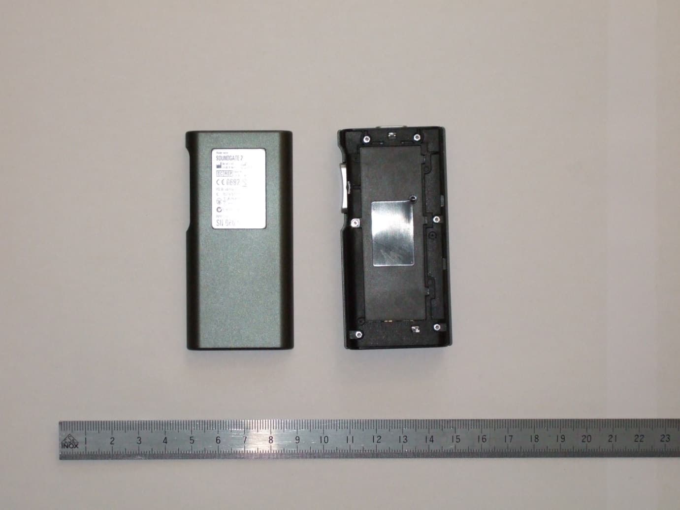
U6XSGATE3
Apr 21, 2013Audio Streaming Device
Equipment Class
DXX - Part 15 Low Power Communication Device Transmitter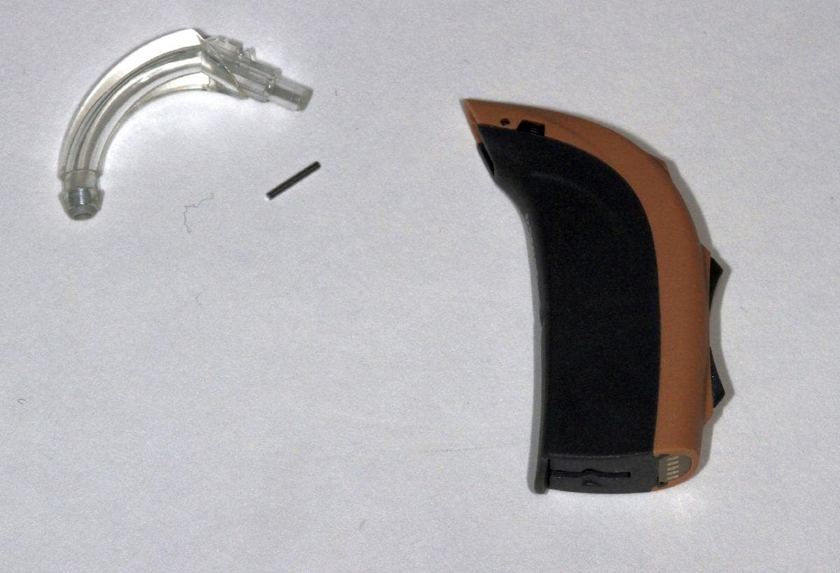
U6XF2BTE02
Apr 03, 2013Hearing Aid (behind the ear)
Equipment Class
DXX - Part 15 Low Power Communication Device Transmitter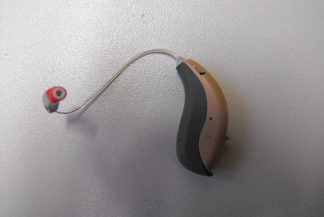
U6XF2RITE2
Dec 19, 2012Wireless Hearing Instrument
Equipment Class
DXX - Part 15 Low Power Communication Device Transmitter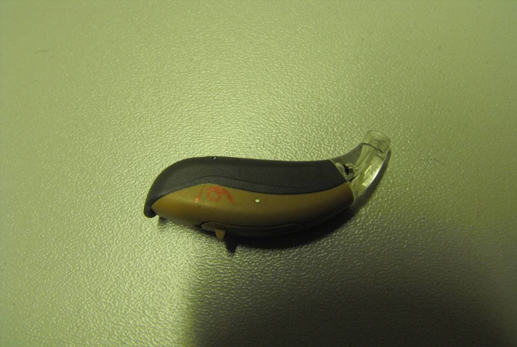
U6XF2BTE01
Dec 19, 2012Wireless Hearing Instrument
Equipment Class
DXX - Part 15 Low Power Communication Device Transmitter