U6XSGATE3Audio Streaming Device
Bernafon AG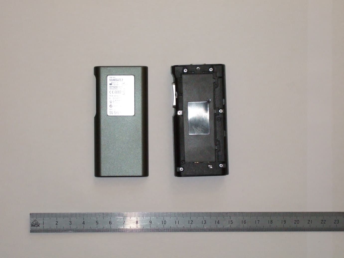
Click to zoom
Application Details
- Equipment Class
- DXX - Part 15 Low Power Communication Device Transmitter
- Date of Grant
- Apr 21, 2013
- Application Purpose
- Original Equipment
- Date of Application
- Apr 21, 2013
- Equipment Note
- Audio Streaming Device
- Frequency Range
- 3.84000000 - 3.84000000
- Company
- Bernafon AG
- Country
- Switzerland
Documents & Files
Document Text
Text extracted from the exhibit documents filed with the FCC. Open a document above to read the original.
Users Manual
S O U N D G at e 2 INStRUCtIONS FOR USe 2 3 Congratulations on the purchase of your new SoundGate 2. Your SoundGate 2 device allows you to connect wirelessly between your hearing instruments and a wide range of audio devices via Bluetooth ® . Whether communicating wirelessly via your mobile telephone device or streaming audio through your television, computer, or MP3 player, this guide will offer the instructions necessary to get you on your way to better hearing. Please read the entire contents of this booklet before using your SoundGate 2 device. It contains instructions and important information about its use and handling. 4 Instructions for Use The following models are covered by these instructions: SoundGate 2 The SoundGate 2 is intended to be used as: 1. A remote control of your hearing instruments. SoundGate 2 may be used as a remote control, enabling you to adjust the hearing instrument volume control and listening programs. 2. A streaming interface between external audio devices and your hearing instruments. The SoundGate 2 may be connected to a large range of audio devices (mobile telephones, TV, etc.) to reduce listening effort. 5 taBLe OF CONteNtS General Warnings and Safety Guidelines 8 Introduction 11 Getting Started 14 Battery Indication 16 Battery Life 18 Attaching the Neck Strap 20 Wearing the SoundGate 2 22 Use of the Protective Skin 23 Microphone 24 SoundGate 2 Operation 25 Turning your SoundGate 2 ON and OFF 26 Volume and Program Adjustment 28 Pairing to a Mobile Telephone or other Bluetooth ® Devices 30 Using with a Mobile Telephone 33 6 7 Using with an MP3 Player or Computer 38 Wired Connection 40 Using the Telephone Coil 42 SoundGate 2 Wireless Range 44 Visual Indicators 47 Troubleshooting 51 Maintenance 58 International Warranty 59 Information to the User Regarding the Radio Communication Part of the Device 61 Declaration of Conformity 64 Information and Explanation of Symbols 65 Service 70 8 General Warnings and Safety Guidelines Familiarize yourself with the following general warnings before using your SoundGate 2 device. Hazard Warnings SoundGate 2 is not a toy and should be kept away from children and anyone else who might swallow parts or otherwise cause injury to themselves. Special attention should be paid to the smaller components in order to prevent swallowing or choking. If a part is swallowed, see a doctor immediately. Never expose the SoundGate 2 to excessive heat, such as putting it in an oven, micro wave, burning it or leaving it inside a parked car in the sun. There is a risk in these events that it will explode and cause serious injur y. 9 If by accident the neck strap should get caught on something while the user is wearing it, the neck strap is constructed to break automatically. Therefore, never try to shorten or modify the neck strap in an unauthorized way. The neck strap should not be used for children who weigh less than 11 kg (24 lbs). Using SoundGate 2 with a mobile telephone while driving may be distracting. If traffic laws or driving conditions demand it, pull off the road and park your vehicle prior to making and answering calls. SoundGate 2 should not be used in an aircraft unless specifically permitted by the flight personnel. SoundGate 2 is designed to comply with the most stringent Standards of International Electromagnetic Compatibility. However, SoundGate 2 might cause inter- ference with other medical devices such as defibrillators and pacemakers. 10 · Please contact the manufacturer of your implantable device for information about the risk of disturbance. · Immediately remove the SoundGate 2 if interference is suspected. Do not use SoundGate 2 and seek advice. Interference can also be caused by power line disturbances, airport metal detectors, electromagnetic fields from other medical devices, radio signals and electrostatic discharges. The safe use of the SoundGate2 with the Auxiliary input cable is determined by an external signal source. When the input cable is connected to mains-operated equipment, this equipment must comply with IEC-60065, IEC-60950, IEC-60601 or equivalent safety standards. The safety of recharging batteries with the USB connector is determined by the external equipment which should be UL approved or comply with equivalent IEC-60065, IEC-60950, IEC-60601 or other equivalent safety standards. 11 Introduction The following items are included within your SoundGate 2 package and will be covered within this instruction guide: SN2_ILLU_Overview_HI 8 SN2_ILLU_Neckloop_HI 2 SoundGate 2 Neck strap 3.5mm stereo cable Power adapter SN2_ILLU_Charger_HI 5 SN2_ILLU_audioCable_HI 4 12 SN2_ILLU_ChargerCradle_HI 3 SN2_ILLU_ProtectiveSkin_HI 6.1 SN2_ILLU_UsbCable_HI 7 SOUNDGATE 2 INSTRUCTIONS FOR USE Instructions for Use USB charging cable Charger cradleProtective skin 13 SoundGate 2 Overview 1 Power on/off 6 Phone key 2 LED indicator 7 Microphone inlet 3 Volume control 8 Neck strap jacks 4 Auxiliary input key 9 3.5 mm auxiliary input 5 TV key 10 Micro-USB charger jack SN2_ILLU_Overview_HI 8 SN2_ILLU_SoundgateProfile_HI 1 4567 10 9 8 3 2 1 8 14 Getting Started The SoundGate 2 contains a rechargeable battery. Ensure your battery is completely charged prior to using your SoundGate 2. Charging the Battery The SoundGate 2 should be charged daily to ensure sufficient battery life during normal hours of operation. The SoundGate 2 can be charged in the following ways: ·Connect the power adapter to the micro-USB charger jack on the SoundGate 2. Then plug the power adapter into a wall socket. SN2_ILLU_Overview_HI 8 15 ·Connect the USB charging cable to the micro-USB charger jack on the SoundGate 2. Then plug the opposite end into the USB port on your computer. ·Plug the power adapter into the micro-USB jack of the charger cradle. Then plug the power adapter into a wall socket, and mount your SoundGate 2 into the cradle with the Power key facing up. ·When using the SoundGate 2 in a vehicle, you may connect the USB charging cable to th…
Text truncated - open the document above for the full version.
ID Label/Location Info
0682 FCC ID : U6XSGATE3 IC: 7031A-SGATE3 12679 9 0 3 /13 SN 1234567 N14144 Bernafon AG Morgenstrasse 131 CH-3018 Bern 2013 Model name: SoundGate 2 T 202-LSB011 D 13-0004 202 Made in Poland INPUT: 5V 500 mA
Test Report
2012-12-19 Page 1 of 33 TEST REPORT Test report no.: 1-4852/12-05-10-A Testing laboratory Applicant CETECOM ICT Services GmbH Untertuerkheimer Strasse 6 – 10 66117 Saarbruecken / Germany Phone: + 49 681 5 98 - 0 Fax: + 49 681 5 98 - 9075 Internet: http://www.cetecom.com e-mail: [email protected] Accredited Testing Laboratory: The testing laboratory (area of testing) is accredited according to DIN EN ISO/IEC 17025 (2005) by the Deutsche Akkreditierungsstelle GmbH (DAkkS) The accreditation is valid for the scope of testing procedures as stated in the accreditation certificate with the registration number: D-PL-12076-01-01 Area of Testing: Radio/Satellite Communications Oticon A/S Kongebakken 9 2765 Smørum / DENMARK Phone: +45 39 17 71 00 Contact: Jørgen Peter Hanuscheck e-mail: [email protected] Phone: +45 39 13 85 38 Manufacturer Oticon A/S Kongebakken 9 2765 Smørum / DENMARK Test standard/s 47 CFR Part 15 Title 47 of the Code of Federal Regulations; Chapter I Part 15 - Radio frequency devices RSS - 210 Issue 8 Spectrum Management and Telecommunications - Radio Standards Specification Low-power Licence-exempt Radiocommunication Devices (All Frequency Bands): Category I Equipment RSS - Gen Issue 3 General Requirements and Information for the Certification of Radiocommunication Equipment For further applied test standards please refer to section 3 of this test report. Test Item Kind of test item: Hearing Aid Accessory Model name: Audio Streaming Module FCC ID: U28CL2STRM IC: 1350B-CL2STRM Frequency: 3.84 MHz Technology tested: Magnetic coupling Antenna: Integrated ferrite – coil antenna; external loop-neck antenna Power Supply: 3.70 V DC by Li – polymer - battery Temperature Range: 0°C to +35 °C This test report is electronically signed and valid without handwriting signature. For verification of the electronic signatures, the public keys can be requested at the testing laboratory. Test report authorised: Test performed: p.o. Stefan Bös Tobias Wittenmeier Testing Manager Test report no.: 1-4852/12-05-10-A 2012-12-19 Page 2 of 33 1 Table of contents 1 Table of contents ............................................................................................................................................ 2 2 General information ....................................................................................................................................... 3 2.1 Notes and disclaimer .......................................................................................................................... 3 2.2 Application details ............................................................................................................................... 3 3 Test standard/s ............................................................................................................................................... 3 4 Test environment ............................................................................................................................................ 4 5 Test item .......................................................................................................................................................... 4 6 Test laboratories sub-contracted ................................................................................................................. 4 7 Summary of measurement results ............................................................................................................... 5 8 RF measurement testing ............................................................................................................................... 6 8.1 Description of test setup .................................................................................................................... 6 8.1.1 Radiated measurements............................................................................................................. 6 8.1.2 Conducted measurements.......................................................................................................... 7 8.2 Additional comments .......................................................................................................................... 7 8.3 RSP100 test report cover sheet / performance test data ................................................................ 8 9 Measurement results ...................................................................................................................................... 9 9.1 Timing of the transmitter .................................................................................................................... 9 9.2 Bandwidth of the modulated carrier ................................................................................................ 10 9.3 Field strength of the fundamental ................................................................................................... 12 9.4 Fieldstrength of the harmonics and spurious ................................................................................ 13 9.5 Receiver spurious emissions ........................................................................................................... 17 9.6 Conducted limits ............................................................................................................................... 18 10 Test equipment and ancillaries used for tests ................................................................................... 20 11 Observations ......................................................................................................................................... 21 Annex A Photographs of the test setup ...................................................................................................... 22 Annex B External photographs of the EUT ................................................................................................. 26 Annex C Internal photographs of the EUT ................…
Text truncated - open the document above for the full version.
Test Setup Photos
Test report no.: 1-4852/12-05-10-A 2012-12-19 Page 22 of 33 Annex A Photographs of the test setup Photo documentation: Photo 1: Photo 2: Test report no.: 1-4852/12-05-10-A 2012-12-19 Page 23 of 33 Photo 3: Photo 4: Test report no.: 1-4852/12-05-10-A 2012-12-19 Page 24 of 33 Photo 5: Photo 6: Test report no.: 1-4852/12-05-10-A 2012-12-19 Page 25 of 33 Photo 7: Photo 8:
Contact Information
Applicant
Per Klaus Nielsen(Certification Manager)
Test Firm
cetecom advanced GmbHGerald Schmidt
Technical Specifications
| # | Rule Parts | Frequency Range | Power Output |
|---|---|---|---|
| 1 | 15C | 3.84 MHz - 3.84 MHz | - |
Other Applications from Bernafon AG
U6XFU2SP
Apr 01, 2015Hearing Aid
Equipment Class
DXX - Part 15 Low Power Communication Device Transmitter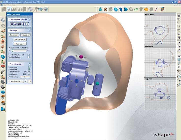
U6XF2ITE01
Apr 09, 2013Hearing Aid (in the ear)
Equipment Class
DXX - Part 15 Low Power Communication Device Transmitter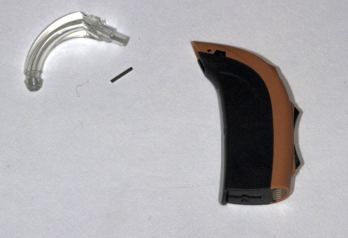
U6XF2BTE02
Apr 03, 2013Hearing Aid (behind the ear)
Equipment Class
DXX - Part 15 Low Power Communication Device Transmitter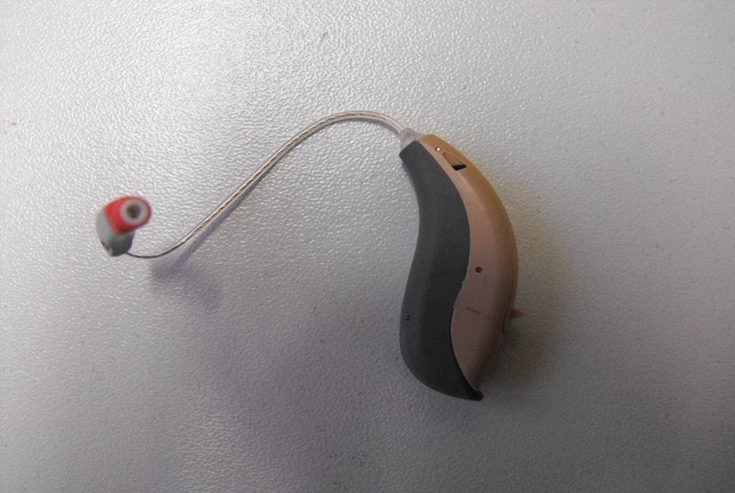
U6XF2RITE2
Dec 19, 2012Wireless Hearing Instrument
Equipment Class
DXX - Part 15 Low Power Communication Device Transmitter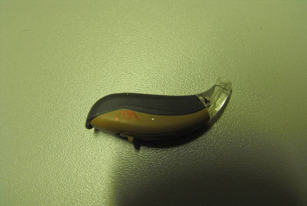
U6XF2BTE01
Dec 19, 2012Wireless Hearing Instrument
Equipment Class
DXX - Part 15 Low Power Communication Device Transmitter