U7G-BLURSMBlu-RSM. Bluetooth Remote Speaker Microphone
Klein Electronics, Inc.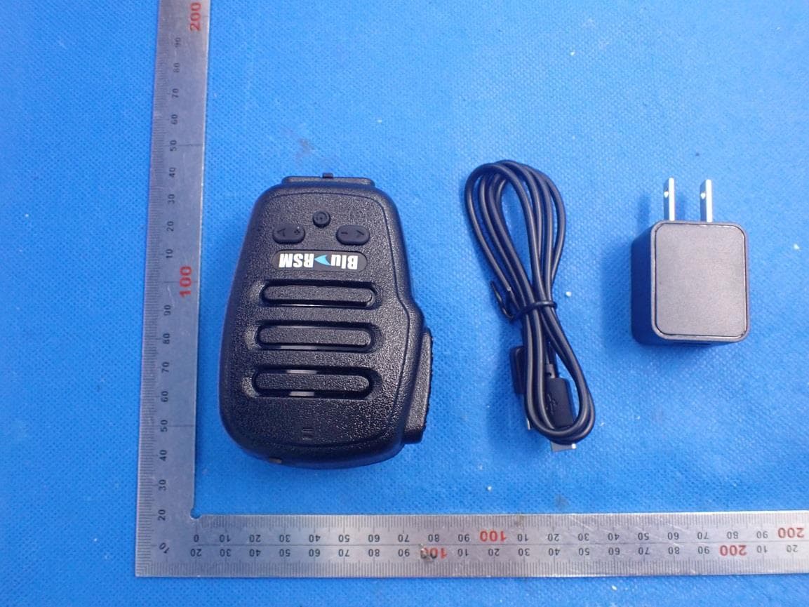
Click to zoom
Application Details
- Equipment Class
- DSS - Part 15 Spread Spectrum Transmitter
- Date of Grant
- Jan 05, 2021
- Application Purpose
- Original Equipment
- Date of Application
- Jan 05, 2021
- Equipment Note
- Blu-RSM. Bluetooth Remote Speaker Microphone
- Frequency Range
- 2402.00000000 - 2480.00000000
- Company
- Klein Electronics, Inc.
- Country
- United States
Documents & Files
Document Text
Text extracted from the exhibit documents filed with the FCC. Open a document above to read the original.
Users Manual
Wandfu - 0 - BLU-RSM Bluetooth Remote Speaker Mic User Guide Wandfu - 1 - Main specification Model BLU-RSM Type of Mic DSP noise cancellation Bluetooth Version V3.0 Class 2 Bluetooth Protocol HSP, HFP, A2DP, AVRCP, PTT Charging Time About 3 hours Music Playing Time About 14 hours Talking Time About 14 hours Standby Time About 500 hours Work Temperature -15°C to 45°C Storage Temperature --25°C to 60°C Type of Battery Lithium battery polymer (1600mA/3.7V) LED light Indicator LED Indicator type Indicated State All LED Indicators off Power off Red/Blue lights flashing alternately Pairing mode Blue light flash once per second Idle mode/working mode Red light flash once per three second Low battery About Charging LED indicator flash mode State of indication Red LED indicator flashing Charging Red LED indicator shinning still Charging completed PS:1.When charging, the headset will reset the system. 2. When the headset has no connection to the mobile phone or other wireless devices, the headset will automatically be turned off 10 minutes later. Wandfu - 2 - Type of Jack Type of Jack diagram Control of Microphone Control of right channel 2-section single side earpiece Built-in Microphone is on. Need to switch off the right channel to save power consumption. Press “+” and “-“ at the same time. The right channel will be turned off and the red light flashes three times. 3-section stereo earpiece Press “+” and “-“ until red/blue light flashing to turn on right channel 4-section stereo earpiece Built-in Microphone is off and out Microphone is on. Press “+” and “-“ until red/blue light flashing to turn on right channel, outside microphone is on while plug in the socket. Remark: Channel control and microphone may be different with different type of Jack. Button Operation Summary Button Operation Function Press the Power button for 3 seconds/8 seconds Switch ON/OFF In the power off status, press the power button for 8 seconds Bluetooth Pairing In the power on status, press “PTT” and “_” for 10 second Clear up the paired record Connection with computer with USB, press power button and “+” button for 3 seconds Upgrading program In paired status, press “PTT” button PTT function In working status, press “+”button Long press for volume increase and short press for next song In working status, press “-“ button Long press for voice decrease and short press for previous song In power on status, press the “+” and “-“ at the same time Red light flash 3 times for right channel off and Red/blue flash 3 times for right channel on. Main Features 1. Push To Talk Function 1) Connect with Dellking Bluetooth adapter/dongle or the relevant cell phone PTT APP. 2) One Key for PTT function. 3) State LED indicator. Wandfu - 3 - 4) Voice indicator of button operation. 5) PTT voice will adapt automatically with the surround environment. 2. Phone Call 1) Bluetooth Hands-free to answer the phone call while paring with cell phone. 2) Last call redial, 3) Answer/Reject phone call 4) Hand-free voice memory function. 5) Hand-free voice adapter automatically to surrounding noise. 3.Music play 1) Support the A2DP profile 2) Capable for listening music from cell phone or other A2DP music resource. 3) Control the music playing of cell phone. 4) Control the music volume. 5) Phone call high priority. 4. Support POC APP Support the PTT APP such as Zello, Azetti, Bper, ESChat, etc,. Let’s take example of Zello App. 1) Press the Power switch for 8 seconds until a “di” sound, the blue/red flashing alternatively. 2) Open the Bluetooth function and search the device or “Dellking PTT Mic”, select the device and connect to cell phone. 3) Open the Zello APP and use the PTT talking function. Remark: Some of the APP need upgrade before usage. Operation Detail Power on/power off 1) In power off state, press Power on/off button and hold it for about 3 seconds, until hear a “di” tone, release the button, blue indicator will flash to indicate power on successfully. 2) In power on state, press Power on/off button and hold it for about 8 seconds, until hear a long “di” tone, all LED indicators will be shut off to indicate the Bluetooth microphone is powered off. Clear up the paring mode Wandfu - 4 - In power on state, press vol“-” and PTT button for 10 seconds until the red lamp on. Upgrade Mode When connected with computer USB port, press vol “+” and switch button for 3 seconds until lamp off. Pairing BLU-RSM and Bluetooth adaptor with two way radio 1) In the power off state, long press microphone power on/off button for 8s, indicator into red and blue flash alternately. 2) When both BT mic and BT adapter red and blue indicator turn to blue flash slowly, pairing success. 3) Now you can press H3 PTT button to control radio and talk. Paring BLU-RSM and mobile phone 1) Make sure the BLU-RSM close to mobile phone within 1meter. 2) Make sure the BLU-RSM is powered off. 3) Long press microphone “power on/off” button for 8s, indicator into red and blue flash alternately (Press minus “-” button to while red/blue flashing alternatively. device need to press “-”during pairing stage). 4) Open mobile phone Bluetooth function, then search device “Blu-RSM”. 5) Select the device “Blu-RSM”and connect to mobile phone. Remark:When the paired mobile phone connect to Speaker Mic, you don’t need to repair and Speaker Mic can connect to mobile phone automatically at Bluetooth status. Or you can short press the switch button for a few second for the connection. Phone call 1) When the Bluetooth speaker microphone connected with mobile phone, microphone can handle the phone calls. 2) Answer incoming call: When there is an incoming phone call, short press “power on/off” button to manual answer the call. 3) Reject incoming phone call: Quick double press “power on/off” button to reject a incoming phone call. 4) Hang up call: In call active state, short press “power on/off” button can hang up the call. 5) Audio transfer: In call active state, press the “power on/off” button for three …
Text truncated - open the document above for the full version.
Cover Letter(s)
Klein Electronics, Inc. Agent Authorization Company: Klein Electronics, Inc. Address: 349 N. Vinewood St Escondido California United States Product Name: Blu-RSM. Bluetooth Remote Speaker Microphone Model Number(s): Blu-RSM Product Description: Blu-RSM. Bluetooth Remote Speaker Microphone We authorize MiCOM Labs Inc., 575 Boulder Court, Pleasanton, California 94566, USA, to act on our behalf on all matters concerning the certification of above named equipment. We declare that MiCOM Labs Inc. is allowed to forward all information related to the approval and certification of equipment to the regulatory agencies as required and to discuss any issues concerning the approval application. Any and all acts carried out by MiCOM Labs on our behalf shall have the same effect as acts of our own. Signature: Date: 2021-01-04 Name: Michael Lopez Company: Klein Electronics, Inc.
Cover Letter(s)
Klein Electronics, Inc. Office of Engineering Technology Federal Communications Commission 7435 Oakland Mills Road Columbia, MD 21046 USA Date: 2020-12-25 Subject; Request for Confidentiality FCC ID: U7G -BLURSM To Whom It May Concern, Pursuant to the provisions of the Commission’s rules Title 47 Sections §0.457 and §0.459, we are requesting the Commission to withhold the following attachment(s) as confidential documents from public disclosure indefinitely. These documents contain detailed system and equipment descriptions and are considered as proprietary information in operation of the equipment. The public disclosure of these documents might be harmful to our company and would give competitors an unfair advantage in the market. Schematic Diagram Block Diagram Parts List Operational Description Tune-up Procedure In additional to above mentioned documents, in order to comply with the marketing regulations in Title 47 CFR §2.803 and the importation rules in Title 47 CFR §2.1204, while ensuring that business sensitive information remains confidential until the actual marketing of newly authorized devices, we request Short Term Confidentiality of the following attachment(s); External Photos Test Setup Photos Internal Photos User Manual For 45 days, pursuant to Public Notice DA 04-1705. OR For 180 days pursuant to KDB 726920 D01. It is our understanding that all measurement test reports, FCC ID label format and correspondence during the certification review process cannot be granted as confidential documents and this information will be available for public review once the grant of equipment authorization is issued. Sincerely Klein Electronics, Inc. Contact person: Richard Klein
External Photos
External Photos ALL VIEW-1 OF EUT EXTERNAL VIEW-1 OF EUT EXTERNAL VIEW-2 OF EUT EXTERNAL VIEW-3 OF EUT EXTERNAL VIEW-4 OF EUT EXTERNAL VIEW-5 OF EUT EXTERNAL VIEW-6 OF EUT EXTERNAL VIEW-7 OF EUT EXTERNAL VIEW-8 OF EUT Adapter
ID Label/Location Info
FCC ID Label Location FCC ID: U7G-BLURSM
Internal Photos
Internal Photos INTERNAL VIEW-1 OF EUT INTERNAL VIEW-2 OF EUT INTERNAL VIEW-3 OF EUT INTERNAL VIEW-4 OF EUT Antenna INTERNAL VIEW-5 OF EUT
RF Exposure Info
RF EXPOSURE EVALUATION 1. PRODUCT INFORMATION Product Description Blu-RSM. Bluetooth Remote Speaker Microphone Model Name Blu-RSM FCC ID U7G-BLURSM 2. EVALUATION METHOD According to 447498 D01 General RF Exposure Guidance v05 The 1-g and 10-g SAR test exclusion thresholds for 100 MHz to 6 GHz at test separation distances ≤ 50 mm are determined by: [(max. power of channel, including tune-up tolerance, mW)/(min. test separation distance, mm)] ·[√f(GHz)] ≤ 3.0 for 1-g SAR and ≤ 7.5 for 10-g extremity SAR. Where f(GHz) is the RF channel transmit frequency in GHz Power and distance are rounded to the nearest mW and mm before calculation 3. CALCULATION BR/EDR: P t = 2.804dBm=1.91mW The value of the Maximum output power P t is referred to the test report of the CFR47 §15.247. The result for RF exposure evaluation SAR=(1.91mW /5mm) .[√2.402GHz)]=0.59<3.0 for 1-g SAR and ≤ 7.5 for 10-g extremity SAR. 4. CONCLUSION The SAR evaluation is not required.
Test Report
Page 1 of 72 FCC Test Report Report No.: AGC02575201201FE03 FCC ID : U7G-BLURSM APPLICATION PURPOSE : Original Equipment PRODUCT DESIGNATION : Blu-RSM. Bluetooth Remote Speaker Microphone BRAND NAME : Klein Electronics, Inc. MODEL NAME : Blu-RSM APPLICANT : Klein Electronics, Inc. DATE OF ISSUE : Dec. 25, 2020 STANDARD(S) : FCC Part 15.247 REPORT VERSION : V1.0 Attestation of Global Compliance (Shenzhen) Co., Ltd Report No.: AGC02575201201FE03 Page 2 of 72 REPORT REVISE RECORD Report Version Revise Time Issued Date Valid Version Notes V1.0 / Dec. 25, 2020 Valid Initial Release Report No.: AGC02575201201FE03 Page 3 of 72 TABLE OF CONTENTS 1. VERIFICATION OF CONFORMITY ............................................................................................................... 5 2. GENERAL INFORMATION ............................................................................................................................ 6 2.1. PRODUCT DESCRIPTION ..................................................................................................................... 6 2.2. TABLE OF CARRIER FREQUENCYS ..................................................................................................... 6 2.3. RECEIVER INPUT BANDWIDTH ............................................................................................................ 7 2.4. EXAMPLE OF A HOPPING SEQUENCY IN DATA MODE ....................................................................... 7 2.5. EQUALLY AVERAGE USE OF FREQUENCIES AND BEHAVIOUR ........................................................ 7 2.6. RELATED SUBMITTAL(S) / GRANT (S) .................................................................................................. 8 2.7. TEST METHODOLOGY .......................................................................................................................... 8 2.8. SPECIAL ACCESSORIES ....................................................................................................................... 8 2.9. EQUIPMENT MODIFICATIONS .............................................................................................................. 8 2.10. ANTENNA REQUIREMENT .................................................................................................................. 8 3. MEASUREMENT UNCERTAINTY ................................................................................................................. 9 4. DESCRIPTION OF TEST MODES ............................................................................................................... 10 5. SYSTEM TEST CONFIGURATION .............................................................................................................. 11 5.1. CONFIGURATION OF EUT SYSTEM .................................................................................................... 11 5.2. EQUIPMENT USED IN TESTED SYSTEM ............................................................................................. 11 5.3. SUMMARY OF TEST RESULTS ............................................................................................................. 11 6. TEST FACILITY ........................................................................................................................................... 12 7. PEAK OUTPUT POWER ............................................................................................................................. 13 7.1. MEASUREMENT PROCEDURE ........................................................................................................... 13 7.2. TEST SET-UP (BLOCK DIAGRAM OF CONFIGURATION) ................................................................... 13 7.3. LIMITS AND MEASUREMENT RESULT ............................................................................................... 14 8. 20DB BANDWIDTH ..................................................................................................................................... 20 8.1. MEASUREMENT PROCEDURE ........................................................................................................... 20 8.2. TEST SET-UP (BLOCK DIAGRAM OF CONFIGURATION) ................................................................... 20 8.3. LIMITS AND MEASUREMENT RESULTS ............................................................................................. 21 9. CONDUCTED SPURIOUS EMISSION ........................................................................................................ 27 9.1. MEASUREMENT PROCEDURE ........................................................................................................... 27 Report No.: AGC02575201201FE03 Page 4 of 72 9.2. TEST SET-UP (BLOCK DIAGRAM OF CONFIGURATION) ................................................................... 27 9.3. MEASUREMENT EQUIPMENT USED .................................................................................................. 27 9.4. LIMITS AND MEASUREMENT RESULT ............................................................................................... 27 10. RADIATED EMISSION ............................................................................................................................... 40 10.1. MEASUREMENT PROCEDURE ......................................................................................................... 40 10.2. TEST SETUP ....................................................................................................................................... 42 10.3. LIMITS AND MEASUREMENT RESULT ............................................................................................. 43 10.4. TEST RESULT ..................................................................................................................................... 43 11. NUMBER OF HOPPING FREQUENCY ..................................................................................................... 53 11.1. MEAS…
Text truncated - open the document above for the full version.
Test Report
Report No.: AGC02575201201FE03 Page 39 of 72 8-DPSK MODULATION IN HIGH CHANNEL Hopping off Hopping on Report No.: AGC02575201201FE03 Page 40 of 72 10. RADIATED EMISSION 10.1. MEASUREMENT PROCEDURE 1. The EUT was placed on the top of the turntable 0.8 or 1.5 meter above ground. The phase center of the receiving antenna mounted on the top of a height-variable antenna tower was placed 3 meters far away from the turntable. 2. Power on the EUT and all the supporting units. The turntable was rotated by 360 degrees to determine the position of the highest radiation. 3. The height of the broadband receiving antenna was varied between one meter and four meters above ground to find the maximum emissions field strength of both horizontal and vertical polarization. 4. For each suspected emission, the antenna tower was scan (from 1 M to 4 M) and then the turntable was rotated (from 0 degree to 360 degrees) to find the maximum reading. 5. Set the test-receiver system to Peak or CISPR quasi-peak Detect Function with specified bandwidth under Maximum Hold Mode. 6. For emissions above 1GHz, use 1MHz RBW and 3MHz VBW for peak reading. Place the measurement antenna away from each area of the EUT determined to be a source of emissions at the specified measurement distance, while keeping the measurement antenna aimed at the source of emissions at each frequency of significant emissions, with polarization oriented for maximum response. The measurement antenna may have to be higher or lower than the EUT, depending on the radiation pattern of the emission and staying aimed at the emission source for receiving the maximum signal. The final measurement antenna elevation shall be that which maximizes the emissions. The measurement antenna elevation for maximum emissions shall be restricted to a range of heights of from 1 m to 4 m above the ground or reference ground plane. 7. When the radiated emissions limits are expressed in terms of the average value of the emissions, and pulsed operation is employed, the measurement field strength shall be determined by averaging over one complete pulse train, including blanking intervals, as long as the pulse train does not exceed 0.1 seconds. As an alternative (provided the transmitter operates for longer than 0.1 seconds) or in cases where the pulse train exceeds 0.1 seconds, the measured field strength shall be determined from the average absolute voltage during a 0.1 second interval during which the field strength is at its maximum values. 8.If the emissions level of the EUT in peak mode was 3 dB lower than the average limit specified, then testing will be stopped and peak values of EUT will be reported, otherwise, the emissions which do not have 3 dB margin will be repeated one by one using the quasi-peak method for below 1GHz. 9. For testing above 1GHz, the emissions level of the EUT in peak mode was lower than average limit (that means the emissions level in peak mode also complies with the limit in average mode), then testing will be stopped and peak values of EUT will be reported, otherwise, the emissions will be measured in average mode again and reported. 10. In case the emission is lower than 30MHz, loop antenna has to be used for measurement and the recorded data should be QP measured by receiver. High - Low scan is not required in this case. Report No.: AGC02575201201FE03 Page 41 of 72 The following table is the setting of spectrum analyzer and receiver. Spectrum Parameter Setting Start ~Stop Frequency 9KHz~150KHz/RB 200Hz for QP Start ~Stop Frequency 150KHz~30MHz/RB 9KHz for QP Start ~Stop Frequency 30MHz~1000MHz/RB 120KHz for QP Start ~Stop Frequency 1GHz~26.5GHz 1MHz/3MHz for Peak, 1MHz/3MHz for Average Receiver Parameter Setting Start ~Stop Frequency 9KHz~150KHz/RB 200Hz for QP Start ~Stop Frequency 150KHz~30MHz/RB 9KHz for QP Start ~Stop Frequency 30MHz~1000MHz/RB 120KHz for QP Report No.: AGC02575201201FE03 Page 42 of 72 10.2. TEST SETUP Radiated Emission Test-Setup Frequency Below 30MHz RADIATED EMISSION TEST SETUP 30MHz-1000MHz RADIATED EMISSION TEST SETUP ABOVE 1000MHz Report No.: AGC02575201201FE03 Page 43 of 72 10.3. LIMITS AND MEASUREMENT RESULT 15.209 Limit in the below table has to be followed Frequencies (MHz) Field Strength (microvolts/meter) Measurement Distance (meters) 0.009~0.490 2400/F(kHz) 300 0.490~1.705 24000/F(kHz) 30 1.705~30.0 30 30 30~88 100 3 88~216 150 3 216~960 200 3 Above 960 500 3 Note: All modes were tested for restricted band radiated emission, the test records reported below are the worst result compared to other modes. 10.4. TEST RESULT RADIATED EMISSION BELOW 30MHz The amplitude of spurious emissions from 9kHz to 30MHz which are attenuated more than 20 dB below the permissible value need not be reported. Report No.: AGC02575201201FE03 Page 44 of 72 RADIATED EMISSION BELOW 1GHz EUT Blu-RSM. Bluetooth Remote Speaker Microphone Model Name Blu-RSM Temperature 25°C Relative Humidity 55.4% Pressure 960hPa Test Voltage Normal Voltage Test Mode Mode 1 Antenna Horizontal NO. Freq. [MHz] Level [dBμV/m] Factor [dB] Limit [dBμV/m] Margin [dB] Height [cm] Angle [°] Polarity 1 30.8500 23.24 10.00 40.00 16.76 200 146 Horizontal 2 52.3000 25.74 11.50 40.00 14.26 200 232 Horizontal 3 66.9250 23.98 9.75 40.00 16.02 200 67 Horizontal 4 119.575 0 19.99 13.43 43.50 23.51 100 27 Horizontal 5 337.000 0 22.06 17.37 46.00 23.94 200 196 Horizontal 6 771.850 0 33.76 27.73 46.00 12.24 200 271 Horizontal RESULT: PASS Report No.: AGC02575201201FE03 Page 45 of 72 EUT Blu-RSM. Bluetooth Remote Speaker Microphone Model Name Blu-RSM Temperature 25°C Relative Humidity 55.4% Pressure 960hPa Test Voltage Normal Voltage Test Mode Mode 1 Antenna Vertical NO. Freq. [MHz] Level [dBμV/m] Factor [dB] Limit [dBμV/m] Margin [dB] Height [cm] Angle [°] Polarity 1 52.3000 26.67 11.50 40.00 13.33 100 315 Vertical 2 66.9250 22.38 9.75 40.00 17.62 100 79 Vertical 3 159.550 0 21.98 14.94 43.50 21.52 100 118 Vertical 4 314.575 0 24.87 16.46 46.00 21.13 100 2 Vertical 5 572.950…
Text truncated - open the document above for the full version.
Test Setup Photos
Test Setup Photos RADIATED EMISSION TEST SETUP BELOW 1GHz RADIATED EMISSION TEST SETUP ABOVE 1GHz CONDUCTED EMISSION TEST SETUP CONDUCTED TEST SETUP
Contact Information
Applicant
Michael Lopez
Technical Contact
Test Firm
Attestation of Global Compliance (Shenzhen) Co., LDoris Li
[email protected]+86-755-25234088
Technical Specifications
| # | Rule Parts | Frequency Range | Power Output |
|---|---|---|---|
| 1 | 15C | 2.40 GHz - 2.48 GHz | 1.90 mW |
Other Applications from Klein Electronics, Inc.

U7GBBGOKP
Jul 08, 2026Digital Portable Radio
Equipment Class
TNF - Licensed Non-Broadcast Transmitter Held to Face
U7GGOVHF
Jul 10, 2023GO
Equipment Class
TNF - Licensed Non-Broadcast Transmitter Held to Face
U7G-FLEX-R
Jan 08, 2023SFR digital mobile radio, SFR repeater
Equipment Class
CSR - Scanning Receiver
U7GBBGRM
Aug 23, 2020Global IOT mobile radio
Equipment Class
PCE - PCS Licensed Transmitter held to ear
U7GPKTPLUS
Aug 20, 2020two way radio
Equipment Class
TNF - Licensed Non-Broadcast Transmitter Held to Face