UFJ282400902Transmitter
Elero USA, Inc.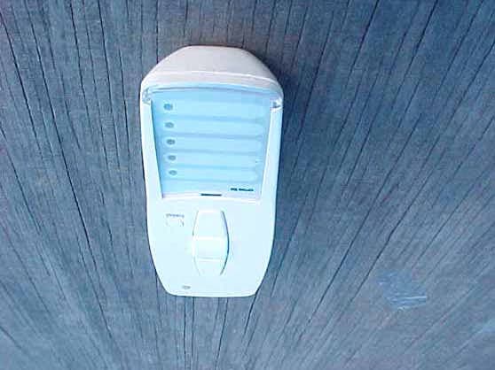
Click to zoom
Application Details
- Equipment Class
- DXX - Part 15 Low Power Communication Device Transmitter
- Date of Grant
- Jul 18, 2006
- Application Purpose
- Original Equipment
- Date of Application
- Jul 18, 2006
- Equipment Note
- Transmitter
- Frequency Range
- 915.35200000 - 915.35200000
- Company
- Elero USA, Inc.
- Country
- United States
Documents & Files
Document Text
Text extracted from the exhibit documents filed with the FCC. Open a document above to read the original.
Users Manual
VarioTel-915 Operating Instructions Please keep the instructions in a safe place. Nr. 18 100.6001/0606 USA el ero 309406 01 elero USA 10827 Alder Circle USA-Dallas Texas 75238 [email protected] elero GmbH Antriebstechnik Linsenhofer Str. 59–63 D-72660 Beuren [email protected] www.elero.com Safety instructions......................................... USA- 2 Instruction to the user..................................... USA- 3 Explanation of buttons.................................... USA- 4 General information....................................... USA- 5 Designated use............................................. USA- 5 Note......................................................... USA- 6 Wall holder installation................................... USA- 6 Explanation of functions.................................. USA- 7 Transmission control light............................ USA- 7 Group control.......................................... USA- 7 Select button........................................... USA- 7 Programming radio channel settings..................... USA- 8 Programming transmitter/channel................... USA- 8 Programming additional transmitters............... USA- 8 Intermediate position for roller shutter/awning/ venetian blind.............................................. USA-10 Programming intermediate position................. USA-10 Programming ventilation/reverse position.......... USA-10 Adjustment to intermediate position................ USA- 11 Adjustment to ventilation/reverse position......... USA- 11 Deleting intermediate position....................... USA- 11 Deleting ventilation/reverse position................ USA- 11 Deleting radio channel settings........................... USA-12 Deleting individual transmitters..................... USA-12 Deleting all transmitters.............................. USA-12 Technical data.............................................. USA-13 Battery replacement....................................... USA-13 Cleaning.................................................... USA-13 Troubleshooting............................................ USA-13 General declaration of conformity........................ USA-13 Contents Safety instructions USA-1USA-2 USA Important safety instructions ! The following instructions must be observed atall times. • For use in dry rooms only. • Use unmodified elerooriginal parts only. • Keep persons away from the systems guide track. • Keep children away from controls. • Always comply with national stipulations. • Always dispose of used batteries properly. Always replace batteries with identical type (LR 03; AAA. • If the system is controlled by one or more transmitters, the system guide track must be visible during operation. • The equipment contains small parts that could be swallowed. Warning! Instruction to the userExplanation of buttons USA-3USA-4 USA elero Select Transmission control light Selectbutton Programming button P Group control lights vUPbutton ySTOPbutton bDOWNbutton Battery compartment Labelling fields This equipment has been tested and found to comply with the limits for a class B digital device, pursuant to part 15 of the FCC Rules. These limits are designed to provide reasonable protection against harmful interference in a residential installation. This equipment generates, uses and can radiate radio frequency energy and if not installed and used in accordance with the instructions, may cause harmful interference to radio communications. However, there is no guarantee that interference will not occur in a particular installation. If this equipment does cause harmful interference to radio or television reception, which can be determined by turning the equipment off and on, the user is encouraged to try to correct the interference by one or more of the following measures: •Reorient or relocate the receiving antenna. •Increase the separation between the equipment and receiver. •Connect the equipment into an outlet on a circuit different from that to which the receiver is connected. •Consult the dealer or an experienced radio/TV technician for help. Operation with non-approved equipment is likely to result in interference to radio and TV reception. The user is cautioned that changes and modifications made to the equipment without the approval of manufacturer could void the user's authority to operate this equipment. Installation USA-5USA-6 USA Note:Radio stations transmitting in the same frequency range may cause reception interference. Please note that the operating range of the radio signal is limited by legislation as well as by the product design Wall holder installation • Before installing the wall holder, always ensure that the transmitter and receiver are in proper working order. • Mount the holder onto the wall using the two raw plugs and screws provided. General information/Designated use General information The VarioTel-915 handheld transmitter can be used to operate up to five receivers individually or altogether. The VarioTel-915 device is characterised by its user-friendly operation. Designated use The VarioTel-915 may be used to operate roller shutters/sun protection systems only. • Please note that radio-controlled systems may notbe used in areas with a high risk of interference (e.g. hospitals, airports). • The remote control is intended solely for use with equipment and systems in which malfunctions in the handheld transmitter or receiver would not pose any risk to persons, animals or property or which contain safety devices to eliminate such risks. • The operator is not protected from interference from other telecommunications systems and terminal equipment (e.g. even from radio-controlled systems which are properly operated in the same frequency range). • Radio receivers may only be used in combination with equipment and systems stipulated in manufacturers’ specifications. Programming radio channel settings USA-7USA-8 USA Programming transmitter/channel Prerequisite:The receiver mus…
Text truncated - open the document above for the full version.
Cover Letter(s)
Mr. Fujimoto: In order for processing of this application (FCC ID: T64282400902) to continue, the following issue(s) will have to be addressed: 1) The grantee code used on the application is invalid for the applicant. 2) An invalid grantee code is used on the FCC ID. 3) The phrase “FCC ID:” and the FCC ID itself must be on the same line. 4) The frequency of operation on the 731 form and the frequency of operation on the test report do not match. Please clarify. 5) A letter from the applicant attesting to the fact that neither the applicant himself, nor any of its officers, directors, or persons holding 5% or more of the outstanding stock or shares, voting or non-voting, have been denied federal benefits under section 5301 of the Anti-Drug-Abuse act of 1988, 21 U.S.C. 853(a) must be submitted. 6) Per section 2.911, the application must be signed by either the applicant or an authorized representative. If signed by an authorized representative, a letter granting that authority must be submitted. 7) FYI – It should be noted that the FCC ID is permitted to be located in the battery compartment only if the it is visible when it is initially removed from its packaging, for instance if the device is sold with the batteries and battery cover removed. The item(s) indicated above must be submitted before processing can continue on the above referenced application. Failure to provide the requested information within 60 days of the original e-mail date may result in application dismissal and forfeiture of the filing fee. Also, please note that partial responses increase processing time and should not be submitted. Please upload responses and/or exhibits to the electronic filing website. Your correspondence number is T64282400902-1.
Cover Letter(s)
http://www.celectronics.com/CorrespondenceByProject.asp?ProjectNumber=-1998891581&Submit=Search Correspondence by Project Project Number: Correspondence Number Memo T64282400902-1 1) The grantee code used on the application is invalid for the applicant. Response: The grantee code has been updated. 2) An invalid grantee code is used on the FCC ID. Response: The FCC-ID Label has been revised to show the correct FCC ID. 3) The phrase “FCC ID:” and the FCC ID itself must be on the same line. Response: The FCC-ID Label has been revised to show the FCC ID itself on the same line. 4) The frequency of operation on the 731 form and the frequency of operation on the test report do not match. Please clarify. Response: Response: The grantee code has been updated. 5) A letter stating Response: This statement is incomplete and thus no action taken. 6) A Letter of Authority must be submitted. Response: The letter of authority has been uploaded. 7) FYI – It should be noted that the FCC ID is permitted to be located in the battery compartment only if the it is visible when it is initially removed from its packaging, for instance if the device is sold with the batteries and battery cover removed. Response: Noted. -1998891581
ID Label/Location Info
Select P 1 2 3 4 5 FCC ID: UFJ282400902This device complies with Part 15 of the FCC Rules.Operation is subject to the following two conditions:(1) This device may not cause harmful interference and(2) this device must accept any interference received, including interference that may cause undesired operation. + AAA - - AAA + FCC ID: UFJ282400902 This device complies with Part 15 of the FCC Rules. Operation is subject to the following two conditions: (1) This device may not cause harmful interference and (2) this device must accept any interference received, including interference that may cause undesired operation. FCC ID: UFJ282400902 The VarioTel Transmitter is a Handheld transmitter with FSK modulation at 915.3 Mhz. It is battery powered and has a loop type antenna soldered to the printed circuit board. It is used to activate a receiver/motor control to operate a reversible motor used in window covering applications such as rolling shutters and retractable awnings. It can control 5 receivers individually or as a group.
Test Report
Report Number: B60314B1 FCC Part 15 Subpart B and FCC Section 15.249 Test Report Transmitter Model: VarioTel-915 Brea Division 114 Olinda Drive Brea, CA 92823 (714) 579-0500 Agoura Division 2337 Troutdale Drive Agoura, CA 91301 (818) 597-0600 Silverado Division 19121 El Toro Road Silverado, CA 92676 (949) 589-0700 Lake Forest Division 20621 Pascal Way Lake Forest, CA 92630 (949) 587-0400 Page 1 of 16 FCC PART 15, SUBPART B and C TEST REPORT for TRANSMITTER MODEL: VarioTel-915 Prepared for ELERO USA, INC. 10827 ALDER CIRCLE DALLAS, TEXAS 75238 Prepared by:_____________________ KYLE FUJIMOTO Approved by:____________________ JAMES ROSS COMPATIBLE ELECTRONICS INC. 114 OLINDA DRIVE BREA, CALIFORNIA 92823 (714) 579-0500 DATE: APRIL 11, 2006 REPORT APPENDICES TOTAL BODY A B C D E PAGES 16 2 2 2 12 9 43 This report shall not be reproduced except in full, without the written approval of Compatible Electronics. Report Number: B60314B1 FCC Part 15 Subpart B and FCC Section 15.249 Test Report Transmitter Model: VarioTel-915 Brea Division 114 Olinda Drive Brea, CA 92823 (714) 579-0500 Agoura Division 2337 Troutdale Drive Agoura, CA 91301 (818) 597-0600 Silverado Division 19121 El Toro Road Silverado, CA 92676 (949) 589-0700 Lake Forest Division 20621 Pascal Way Lake Forest, CA 92630 (949) 587-0400 Page 2 of 16 TABLE OF CONTENTS Section / Title PAGE GENERAL REPORT SUMMARY 4 SUMMARY OF TEST RESULTS 4 1. PURPOSE 5 2. ADMINISTRATIVE DATA 6 2.1 Location of Testing 6 2.2 Traceability Statement 6 2.3 Cognizant Personnel 6 2.4 Date Test Sample was Received 6 2.5 Disposition of the Test Sample 6 2.6 Abbreviations and Acronyms 6 3. APPLICABLE DOCUMENTS 7 4. DESCRIPTION OF TEST CONFIGURATION 8 4.1 Description Of Test Configuration - EMI 8 4.1.1 Cable Construction and Termination 9 5. LISTS OF EUT, ACCESSORIES AND TEST EQUIPMENT 10 5.1 EUT and Accessory List 10 5.2 EMI Test Equipment 11 6. TEST SITE DESCRIPTION 12 6.1 Test Facility Description 12 6.2 EUT Mounting, Bonding and Grounding 12 7. TEST PROCEDURES 13 7.1 Conducted Emissions Test 13 7.2 Radiated Emissions (Spurious and Harmonics) Test 14 7.3 Radiated Emissions (Spurious and Harmonics) Test (continued) 15 8. CONCLUSIONS 16 Report Number: B60314B1 FCC Part 15 Subpart B and FCC Section 15.249 Test Report Transmitter Model: VarioTel-915 Brea Division 114 Olinda Drive Brea, CA 92823 (714) 579-0500 Agoura Division 2337 Troutdale Drive Agoura, CA 91301 (818) 597-0600 Silverado Division 19121 El Toro Road Silverado, CA 92676 (949) 589-0700 Lake Forest Division 20621 Pascal Way Lake Forest, CA 92630 (949) 587-0400 Page 3 of 16 LIST OF APPENDICES APPENDIX TITLE A Laboratory Recognitions B Modifications to the EUT C Additional Models Covered Under This Report D Diagrams, Charts, and Photos • Test Setup Diagrams • Radiated Emissions Photos • Antenna and Effective Gain Factors E Data Sheets LIST OF FIGURES FIGURE TITLE 1 Plot Map And Layout of Radiated Site Report Number: B60314B1 FCC Part 15 Subpart B and FCC Section 15.249 Test Report Transmitter Model: VarioTel-915 Brea Division 114 Olinda Drive Brea, CA 92823 (714) 579-0500 Agoura Division 2337 Troutdale Drive Agoura, CA 91301 (818) 597-0600 Silverado Division 19121 El Toro Road Silverado, CA 92676 (949) 589-0700 Lake Forest Division 20621 Pascal Way Lake Forest, CA 92630 (949) 587-0400 Page 4 of 16 GENERAL REPORT SUMMARY This electromagnetic emission test report is generated by Compatible Electronics Inc., which is an independent testing and consulting firm. The test report is based on testing performed by Compatible Electronics personnel according to the measurement procedures described in the test specifications given below and in the "Test Procedures" section of this report. The measurement data and conclusions appearing herein relate only to the sample tested and this report may not be reproduced without the written permission of Compatible Electronics, unless done so in full. This report must not be used to claim product endorsement by NVLAP, NIST or any other agency of the U.S. Government. Device Tested: Transmitter Model: VarioTel-915 S/N: N/A Product Description: See Expository Statement Modifications: The EUT was not modified in order to meet the specifications. Manufacturer: Elero USA, Inc. 10827 Alder Circle Dallas, Texas 75238 Test Date: March 14, 2006 Test Specifications : EMI requirements CFR Title 47, Part 15 Subpart B; and Subpart C, Sections 15.205, 15.209 and 15.249 Test Procedure: ANSI C63.4 Test Deviations: The test procedure was not deviated from during the testing. SUMMARY OF TEST RESULTS TEST DESCRIPTION RESULTS 1 Conducted RF Emissions, 150 kHz - 30 MHz This test was not performed because the EUT is battery powered only and does not connect to the AC public mains. 2 Radiated RF Emissions, 10 kHz - 9300 MHz Complies with the Class B limits of CFR Title 47, Part 15, Subpart B; and Subpart C, sections 15.205, 15.209, and 15.249. Report Number: B60314B1 FCC Part 15 Subpart B and FCC Section 15.249 Test Report Transmitter Model: VarioTel-915 Brea Division 114 Olinda Drive Brea, CA 92823 (714) 579-0500 Agoura Division 2337 Troutdale Drive Agoura, CA 91301 (818) 597-0600 Silverado Division 19121 El Toro Road Silverado, CA 92676 (949) 589-0700 Lake Forest Division 20621 Pascal Way Lake Forest, CA 92630 (949) 587-0400 Page 5 of 16 1. PURPOSE This document is a qualification test report based on the Electromagnetic Interference (EMI) tests performed on the Transmitter Model: VarioTel-915. The EMI measurements were performed according to the measurement procedure described in ANSI C63.4. The tests were performed in order to determine whether the electromagnetic emissions from the equipment under test, referred to as EUT hereafter, are within the Class B specification limits defined by CFR Title 47, Part 15, Subpart B; and Subpart C, sections 15.205, 15.209, and 15.249. Report Number: B60314B1 FCC Part 15 Subpart B and FCC Section 15.249 Test Report Transmitter Model: VarioTel-915 Brea Division 114 …
Text truncated - open the document above for the full version.
Contact Information
Applicant
David Harned(Technical Director)
Technical Contact
Compatible Electronics, Inc.Kyle Fujimoto
[email protected]714-579-0500
114 Olinda Drive · Brea, California · United States
Test Firm
Compatible Electronics, Inc.Michael Christensen
Technical Specifications
| # | Rule Parts | Frequency Range | Power Output |
|---|---|---|---|
| 1 | 15C | 915.352 MHz - 915.352 MHz | - |
Other Applications from Elero USA, Inc.
UFJ283000902
Jul 31, 2006Transmitter
Equipment Class
DXX - Part 15 Low Power Communication Device Transmitter
UFJ282000902
Jul 27, 2006Transmitter
Equipment Class
DXX - Part 15 Low Power Communication Device Transmitter
UFJ282200902
Jul 18, 2006Transmitter
Equipment Class
DXX - Part 15 Low Power Communication Device Transmitter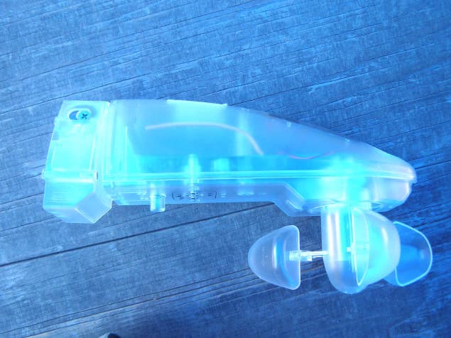
UFJ284400902
Jul 18, 2006Transmitter
Equipment Class
DXX - Part 15 Low Power Communication Device Transmitter
UFJ283200902
Jul 18, 2006Transmitter
Equipment Class
DXX - Part 15 Low Power Communication Device Transmitter