UFJ284400902Transmitter
Elero USA, Inc.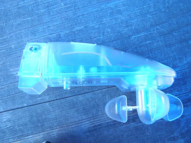
Click to zoom
Application Details
- Equipment Class
- DXX - Part 15 Low Power Communication Device Transmitter
- Date of Grant
- Jul 18, 2006
- Application Purpose
- Original Equipment
- Date of Application
- Jul 17, 2006
- Equipment Note
- Transmitter
- Frequency Range
- 915.25000000 - 915.25000000
- Company
- Elero USA, Inc.
- Country
- United States
Documents & Files
Document Text
Text extracted from the exhibit documents filed with the FCC. Open a document above to read the original.
Users Manual
Aero-915/Aero-915 Plus Operating instructions 28 440.0002/28 480.0001 Warning! Important safety instructions! Observe the following instructions. • Only use unmodified original eleroelectrical parts. • Keep persons away from the operating range of the system. • Keep children away from the controls. • Follow the relevant country-specific regulations. • If one or more devices are used for controlling the system, the operating range must stay visible during operation. • The device contains swallowable small parts. • Up- or downwinds blowing against façades may cause destruction of equipment. • The Aero-915/Aero-915 Plus is notable to recognise these. • Please pay attention to this advice when choosing your mounting position. General information Aero-915 is a wireless sun/wind control device for your awning. Integrated solar cells enable autonomous function of the device. Radio signals (frequency 915 MHz) are transmitted between the Aero-915 and the receiver. Important! The Aero-915/Aero-915 Plus only operates in connection with radio receivers of the elero ProLine-915 radio system. Special features of the Aero-915 Plus The Aero-915 Plus is equipped with an additional energy store and an additional solar cell. The standby-time is 14 hours. The awning can be operated manually via a manual/wall trans- mitter. This item is not included in the scope of delivery. Recommendation:Use a LumeroTel or VarioTelPlus manual trans- mitter in connection with the Aero-915/Aero-915 Plus to deactivate the sun function. Safety instructions b b v b b 80 200 135 b b 35 b b 66 Intended use The Aero-915 AC may onlybe used for control of awnings and venetian blind installations. Third-party devices should only be connected after consultation with your specialised dealer. •Please ensure that the radio installations are not operated in areas of heightened possible interference. (e.g. hospitals, airports ...). •The remote control is only approved for devices and systems for which any malfunction of the manual transmitter or receiver would not result in a risk for persons, animals or property, or if such a risk is covered by other safety devices. •The operator has no protection whatsoever from interferences by other radio emitters and local terminals (e.g. also from radio installations), that are normally used on the same frequency range. •Only use radio receivers with equipment and units approved by the manufacturer. 10 12 14 2 Off 8 4 6 11 1 3 9 5 7 yellow LED (light value) red LED (Wind value) green LED (transmit) DOWN button (Sun symbol) UPbutton (Wind symbol) USA CA Instruction to the user This equipment has been tested and found to comply with the limits for a class B digital device, pursuant to part 15 of the FCC Rules. These limits are designed to provide reasonable protection against harmful interference in a residential installation. This equipment generates, uses and can radiate radio frequency ener- gy and if not installed and used in accordance with the instruc- tions, may cause harmful interference to radio communications. However, there is no guarantee that interference will not occur in a particular installation. If this equipment does cause harmful interference to radio or television reception, which can be determined by turning the equipment off and on, the user is encouraged to try to correct the interference by one or more of the following measures: •Reorient or relocate the receiving antenna. •Increase the separation between the equipment and receiver. •Connect the equipment into an outlet on a circuit different from that to which the receiver is connected. •Consult the dealer or an experienced radio/TV technician for help. Operation with non-approved equipment is likely to result in interference to radio and TV reception. The user is cautioned that changes and modifications made to the equipment without the approval of manufacturer could void the user's authority to operate this equipment. 2 Function for "Auto" switch setting (manual transmitter) The UP-STOP-DOWNbutton on the manual transmitter and the UP/DOWNkeys at the Aero-915 are active. –Wind monitoring is active –Sun protection is active. Semi-automatic mode Your Aero-915/Aero-915 Plus is in AUTO mode. As soon as you now press a button on your programmed manual transmitter the receiver switches itself into the semi-automatic mode. Leave semi-automatic mode: –If a level falls below and/or rises above a set threshold value then the system automatically changes to AUTO mode. The system moves in/out. or –Set the sliding switch of your transmitter briefly to MANUAL mode and then to AUTO mode. The system moves in. Loading the Aero-915/Aero-915 Plus The Aero-915 is supplied in discharged condition. 1. Prior to commissioning, load the Aero-915 for at least minimum 30 minutes under a lamp or press a travel key for at least 1 minute. Advice:the travel keys have two settings. The first setting transfers energy from a built-in cell to the energy store. The second setting activates the travel command. Programming the Aero-915/Aero-915 Plus Condition: The end positions of the awing are set, a transmitter is programmed. Start teach mode 1. Blind/shutter runs up and down for 2minutes. min. 3 sec. elero 2. 3. STOP STOP Press the ”UP” (wind symbol) button imme- diately after the start of upward travel . Press the ” DOWN” (sun symbol) button immedia- telyafter the start of downward travel. "Teach-in" programmed transmitter. 10 12 14 2 Off 8 4 6 11 1 3 9 5 7 10 12 14 2 Off 8 4 6 11 1 3 9 5 7 Setting the threshold values Multiple contact switches for wind and sun are located at the underside of the Aero-915. The switch has several settings, which can be modified with a small screwdriver.. Wind Setting 1➯Retract at low wind speed Setting 2 bis 10➯Intermediate levels Setting 4➯Factory setting Setting 11 ➯Retract at high wind speeds Sun Setting OFF ➯Light function is deactivated Setting 1 ➯Move out at low light levels Setting 2 bis 13 ➯Intermediate levels Setting 4…
Text truncated - open the document above for the full version.
Users Manual
Aero-915/Aero-915 Plus Operating instructions 28 440.0002/28 480.0001 Warning! Important safety instructions! Observe the following instructions. • Only use unmodified original eleroelectrical parts. • Keep persons away from the operating range of the system. • Keep children away from the controls. • Follow the relevant country-specific regulations. • If one or more devices are used for controlling the system, the operating range must stay visible during operation. • The device contains swallowable small parts. • Up- or downwinds blowing against façades may cause destruction of equipment. • The Aero-915/Aero-915 Plus is notable to recognise these. • Please pay attention to this advice when choosing your mounting position. General information Aero-915 is a wireless sun/wind control device for your awning. Integrated solar cells enable autonomous function of the device. Radio signals (frequency 915 MHz) are transmitted between the Aero-915 and the receiver. Important! The Aero-915/Aero-915 Plus only operates in connection with radio receivers of the elero ProLine-915 radio system. Special features of the Aero-915 Plus The Aero-915 Plus is equipped with an additional energy store and an additional solar cell. The standby-time is 14 hours. The awning can be operated manually via a manual/wall trans- mitter. This item is not included in the scope of delivery. Recommendation:Use a LumeroTel or VarioTelPlus manual trans- mitter in connection with the Aero-915/Aero-915 Plus to deactivate the sun function. Safety instructions b b v b b 80 200 135 b b 35 b b 66 Intended use The Aero-915 AC may onlybe used for control of awnings and venetian blind installations. Third-party devices should only be connected after consultation with your specialised dealer. •Please ensure that the radio installations are not operated in areas of heightened possible interference. (e.g. hospitals, airports ...). •The remote control is only approved for devices and systems for which any malfunction of the manual transmitter or receiver would not result in a risk for persons, animals or property, or if such a risk is covered by other safety devices. •The operator has no protection whatsoever from interferences by other radio emitters and local terminals (e.g. also from radio installations), that are normally used on the same frequency range. •Only use radio receivers with equipment and units approved by the manufacturer. 10 12 14 2 Off 8 4 6 11 1 3 9 5 7 yellow LED (light value) red LED (Wind value) green LED (transmit) DOWN button (Sun symbol) UPbutton (Wind symbol) USA CA Instruction to the user This equipment has been tested and found to comply with the limits for a class B digital device, pursuant to part 15 of the FCC Rules. These limits are designed to provide reasonable protection against harmful interference in a residential installation. This equipment generates, uses and can radiate radio frequency ener- gy and if not installed and used in accordance with the instruc- tions, may cause harmful interference to radio communications. However, there is no guarantee that interference will not occur in a particular installation. If this equipment does cause harmful interference to radio or television reception, which can be determined by turning the equipment off and on, the user is encouraged to try to correct the interference by one or more of the following measures: •Reorient or relocate the receiving antenna. •Increase the separation between the equipment and receiver. •Connect the equipment into an outlet on a circuit different from that to which the receiver is connected. •Consult the dealer or an experienced radio/TV technician for help. Operation with non-approved equipment is likely to result in interference to radio and TV reception. The user is cautioned that changes and modifications made to the equipment without the approval of manufacturer could void the user's authority to operate this equipment. 2 Function for "Auto" switch setting (manual transmitter) The UP-STOP-DOWNbutton on the manual transmitter and the UP/DOWNkeys at the Aero-915 are active. –Wind monitoring is active –Sun protection is active. Semi-automatic mode Your Aero-915/Aero-915 Plus is in AUTO mode. As soon as you now press a button on your programmed manual transmitter the receiver switches itself into the semi-automatic mode. Leave semi-automatic mode: –If a level falls below and/or rises above a set threshold value then the system automatically changes to AUTO mode. The system moves in/out. or –Set the sliding switch of your transmitter briefly to MANUAL mode and then to AUTO mode. The system moves in. Loading the Aero-915/Aero-915 Plus The Aero-915 is supplied in discharged condition. 1. Prior to commissioning, load the Aero-915 for at least minimum 30 minutes under a lamp or press a travel key for at least 1 minute. Advice:the travel keys have two settings. The first setting transfers energy from a built-in cell to the energy store. The second setting activates the travel command. Programming the Aero-915/Aero-915 Plus Condition: The end positions of the awing are set, a transmitter is programmed. Start teach mode 1. Blind/shutter runs up and down for 2minutes. min. 3 sec. elero 2. 3. STOP STOP Press the ”UP” (wind symbol) button imme- diately after the start of upward travel . Press the ” DOWN” (sun symbol) button immedia- telyafter the start of downward travel. "Teach-in" programmed transmitter. 10 12 14 2 Off 8 4 6 11 1 3 9 5 7 10 12 14 2 Off 8 4 6 11 1 3 9 5 7 Setting the threshold values Multiple contact switches for wind and sun are located at the underside of the Aero-915. The switch has several settings, which can be modified with a small screwdriver.. Wind Setting 1➯Retract at low wind speed Setting 2 bis 10➯Intermediate levels Setting 4➯Factory setting Setting 11 ➯Retract at high wind speeds Sun Setting OFF ➯Light function is deactivated Setting 1 ➯Move out at low light levels Setting 2 bis 13 ➯Intermediate levels Setting 4…
Text truncated - open the document above for the full version.
Cover Letter(s)
Mr. Fujimoto: In order for processing of this application (FCC ID: T64284400902) to continue, the following issue(s) will have to be addressed: 1) The grantee code used on the application is invalid for the applicant. 2) An invalid grantee code is used on the FCC ID. 3) No data was submitted for the Z axis in the horizontal polarization, 2 nd through 7 th harmonics. Please submit all test data. The item(s) indicated above must be submitted before processing can continue on the above referenced application. Failure to provide the requested information within 60 days of the original e-mail date may result in application dismissal and forfeiture of the filing fee. Also, please note that partial responses increase processing time and should not be submitted. Please upload responses and/or exhibits to the electronic filing website. Your correspondence number is T64284400902-1.
Cover Letter(s)
http://www.celectronics.com/CorrespondenceByProject.asp?ProjectNumber=-850797143&Submit=Search Correspondence by Project Project Number: Correspondence Number Memo T64284400902-1 1) The grantee code used on the application is invalid for the applicant. Response: The Grantee Code has bee revised to show the correct grantee code. 2) An invalid grantee code is used on the FCC ID. Response: The FCC-ID has been revised to show the correct grantee code. 3) No data was submitted for the Z axis in the horizontal polarization, 2nd through 7th harmonics. Please submit all test data. Response: The test report has been revised to include this data, which was accidently omitted before. -850797143
ID Label/Location Info
1 3 5 7 9 11 off 2 4 6 8 10 12 14 FCC ID: UFJ284400902 This device complies with Part 15 of the FCC Rules. Operation is subject to the following two conditions: (1) This device may not cause harmful interference and (2) this device must accept any interference received, including interference that may cause undesired operation. FCC ID: UFJ284400902 This device complies with Part 15 of the FCC Rules. Operation is subject to the following two conditions: (1) This device may not cause harmful interference and (2) this device must accept any interference received, including interference that may cause undesired operation. FCC ID: UFJ284400902 The Aero Transmitter is a wall mounted transmitter with FSK modulation at 915.3 Mhz. It is solar cell powered and has a loop type antenna soldered to the printed circuit board. It is used to activate a receiver/motor control to operate a reversible motor used in window covering applications such as rolling shutters and retractable awnings. It includes a wind anemometer and a light sensor for operating the shading device based on light and wind conditions.
ID Label/Location Info
1 3 5 7 9 11 off 2 4 6 8 10 12 14 FCC ID: UFJ284400902 This device complies with Part 15 of the FCC Rules. Operation is subject to the following two conditions: (1) This device may not cause harmful interference and (2) this device must accept any interference received, including interference that may cause undesired operation. FCC ID: UFJ284400902 This device complies with Part 15 of the FCC Rules. Operation is subject to the following two conditions: (1) This device may not cause harmful interference and (2) this device must accept any interference received, including interference that may cause undesired operation. FCC ID: UFJ284400902 The Aero Transmitter is a wall mounted transmitter with FSK modulation at 915.3 Mhz. It is solar cell powered and has a loop type antenna soldered to the printed circuit board. It is used to activate a receiver/motor control to operate a reversible motor used in window covering applications such as rolling shutters and retractable awnings. It includes a wind anemometer and a light sensor for operating the shading device based on light and wind conditions.
Test Report
Report Number: B60321D1 FCC Part 15 Subpart B and FCC Section 15.249 Test Report Transmitter Model: Aero-915 Brea Division 114 Olinda Drive Brea, CA 92823 (714) 579-0500 Agoura Division 2337 Troutdale Drive Agoura, CA 91301 (818) 597-0600 Silverado Division 19121 El Toro Road Silverado, CA 92676 (949) 589-0700 Lake Forest Division 20621 Pascal Way Lake Forest, CA 92630 (949) 587-0400 Page 1 of 16 FCC PART 15, SUBPART B and C TEST REPORT for TRANSMITTER MODEL: Aero-915 Prepared for ELERO USA, INC. 10827 ALDER CIRCLE DALLAS, TEXAS 75238 Prepared by:_____________________ KYLE FUJIMOTO Approved by:____________________ JAMES ROSS COMPATIBLE ELECTRONICS INC. 114 OLINDA DRIVE BREA, CALIFORNIA 92823 (714) 579-0500 DATE: APRIL 11, 2006 REPORT APPENDICES TOTAL BODY A B C D E PAGES 16 2 2 2 12 9 43 This report shall not be reproduced except in full, without the written approval of Compatible Electronics. Report Number: B60321D1 FCC Part 15 Subpart B and FCC Section 15.249 Test Report Transmitter Model: Aero-915 Brea Division 114 Olinda Drive Brea, CA 92823 (714) 579-0500 Agoura Division 2337 Troutdale Drive Agoura, CA 91301 (818) 597-0600 Silverado Division 19121 El Toro Road Silverado, CA 92676 (949) 589-0700 Lake Forest Division 20621 Pascal Way Lake Forest, CA 92630 (949) 587-0400 Page 2 of 16 TABLE OF CONTENTS Section / Title PAGE GENERAL REPORT SUMMARY 4 SUMMARY OF TEST RESULTS 4 1. PURPOSE 5 2. ADMINISTRATIVE DATA 6 2.1 Location of Testing 6 2.2 Traceability Statement 6 2.3 Cognizant Personnel 6 2.4 Date Test Sample was Received 6 2.5 Disposition of the Test Sample 6 2.6 Abbreviations and Acronyms 6 3. APPLICABLE DOCUMENTS 7 4. DESCRIPTION OF TEST CONFIGURATION 8 4.1 Description Of Test Configuration - EMI 8 4.1.1 Cable Construction and Termination 9 5. LISTS OF EUT, ACCESSORIES AND TEST EQUIPMENT 10 5.1 EUT and Accessory List 10 5.2 EMI Test Equipment 11 6. TEST SITE DESCRIPTION 12 6.1 Test Facility Description 12 6.2 EUT Mounting, Bonding and Grounding 12 7. TEST PROCEDURES 13 7.1 Conducted Emissions Test 13 7.2 Radiated Emissions (Spurious and Harmonics) Test 14 7.3 Radiated Emissions (Spurious and Harmonics) Test (continued) 15 8. CONCLUSIONS 16 Report Number: B60321D1 FCC Part 15 Subpart B and FCC Section 15.249 Test Report Transmitter Model: Aero-915 Brea Division 114 Olinda Drive Brea, CA 92823 (714) 579-0500 Agoura Division 2337 Troutdale Drive Agoura, CA 91301 (818) 597-0600 Silverado Division 19121 El Toro Road Silverado, CA 92676 (949) 589-0700 Lake Forest Division 20621 Pascal Way Lake Forest, CA 92630 (949) 587-0400 Page 3 of 16 LIST OF APPENDICES APPENDIX TITLE A Laboratory Recognitions B Modifications to the EUT C Additional Models Covered Under This Report D Diagrams, Charts, and Photos • Test Setup Diagrams • Radiated Emissions Photos • Antenna and Effective Gain Factors E Data Sheets LIST OF FIGURES FIGURE TITLE 1 Plot Map And Layout of Radiated Site Report Number: B60321D1 FCC Part 15 Subpart B and FCC Section 15.249 Test Report Transmitter Model: Aero-915 Brea Division 114 Olinda Drive Brea, CA 92823 (714) 579-0500 Agoura Division 2337 Troutdale Drive Agoura, CA 91301 (818) 597-0600 Silverado Division 19121 El Toro Road Silverado, CA 92676 (949) 589-0700 Lake Forest Division 20621 Pascal Way Lake Forest, CA 92630 (949) 587-0400 Page 4 of 16 GENERAL REPORT SUMMARY This electromagnetic emission test report is generated by Compatible Electronics Inc., which is an independent testing and consulting firm. The test report is based on testing performed by Compatible Electronics personnel according to the measurement procedures described in the test specifications given below and in the "Test Procedures" section of this report. The measurement data and conclusions appearing herein relate only to the sample tested and this report may not be reproduced without the written permission of Compatible Electronics, unless done so in full. This report must not be used to claim product endorsement by NVLAP, NIST or any other agency of the U.S. Government. Device Tested: Transmitter Model: Aero-915 S/N: N/A Product Description: See Expository Statement Modifications: The EUT was not modified in order to meet the specifications. Manufacturer: Elero USA, Inc. 10827 Alder Circle Dallas, Texas 75238 Test Date: March 21, 2006 Test Specifications : EMI requirements CFR Title 47, Part 15 Subpart B; and Subpart C, Sections 15.205, 15.209 and 15.249 Test Procedure: ANSI C63.4 Test Deviations: The test procedure was not deviated from during the testing. SUMMARY OF TEST RESULTS TEST DESCRIPTION RESULTS 1 Conducted RF Emissions, 150 kHz - 30 MHz This test was not performed because the EUT is battery powered only and does not connect to the AC public mains. 2 Radiated RF Emissions, 10 kHz - 9300 MHz Complies with the Class B limits of CFR Title 47, Part 15, Subpart B; and Subpart C, sections 15.205, 15.209, and 15.249. Report Number: B60321D1 FCC Part 15 Subpart B and FCC Section 15.249 Test Report Transmitter Model: Aero-915 Brea Division 114 Olinda Drive Brea, CA 92823 (714) 579-0500 Agoura Division 2337 Troutdale Drive Agoura, CA 91301 (818) 597-0600 Silverado Division 19121 El Toro Road Silverado, CA 92676 (949) 589-0700 Lake Forest Division 20621 Pascal Way Lake Forest, CA 92630 (949) 587-0400 Page 5 of 16 1. PURPOSE This document is a qualification test report based on the Electromagnetic Interference (EMI) tests performed on the Transmitter Model: Aero-915. The EMI measurements were performed according to the measurement procedure described in ANSI C63.4. The tests were performed in order to determine whether the electromagnetic emissions from the equipment under test, referred to as EUT hereafter, are within the Class B specification limits defined by CFR Title 47, Part 15, Subpart B; and Subpart C, sections 15.205, 15.209, and 15.249. Report Number: B60321D1 FCC Part 15 Subpart B and FCC Section 15.249 Test Report Transmitter Model: Aero-915 Brea Division 114 Olinda Drive Brea, CA 92823 (714) 57…
Text truncated - open the document above for the full version.
Test Report
Report Number: B60321D1 FCC Part 15 Subpart B and FCC Section 15.249 Test Report Transmitter Model: Aero-915 Brea Division 114 Olinda Drive Brea, CA 92823 (714) 579-0500 Agoura Division 2337 Troutdale Drive Agoura, CA 91301 (818) 597-0600 Silverado Division 19121 El Toro Road Silverado, CA 92676 (949) 589-0700 Lake Forest Division 20621 Pascal Way Lake Forest, CA 92630 (949) 587-0400 Page 1 of 16 FCC PART 15, SUBPART B and C TEST REPORT for TRANSMITTER MODEL: Aero-915 Prepared for ELERO USA, INC. 10827 ALDER CIRCLE DALLAS, TEXAS 75238 Prepared by:_____________________ KYLE FUJIMOTO Approved by:____________________ JAMES ROSS COMPATIBLE ELECTRONICS INC. 114 OLINDA DRIVE BREA, CALIFORNIA 92823 (714) 579-0500 DATE: APRIL 11, 2006 REPORT APPENDICES TOTAL BODY A B C D E PAGES 16 2 2 2 12 9 43 This report shall not be reproduced except in full, without the written approval of Compatible Electronics. Report Number: B60321D1 FCC Part 15 Subpart B and FCC Section 15.249 Test Report Transmitter Model: Aero-915 Brea Division 114 Olinda Drive Brea, CA 92823 (714) 579-0500 Agoura Division 2337 Troutdale Drive Agoura, CA 91301 (818) 597-0600 Silverado Division 19121 El Toro Road Silverado, CA 92676 (949) 589-0700 Lake Forest Division 20621 Pascal Way Lake Forest, CA 92630 (949) 587-0400 Page 2 of 16 TABLE OF CONTENTS Section / Title PAGE GENERAL REPORT SUMMARY 4 SUMMARY OF TEST RESULTS 4 1. PURPOSE 5 2. ADMINISTRATIVE DATA 6 2.1 Location of Testing 6 2.2 Traceability Statement 6 2.3 Cognizant Personnel 6 2.4 Date Test Sample was Received 6 2.5 Disposition of the Test Sample 6 2.6 Abbreviations and Acronyms 6 3. APPLICABLE DOCUMENTS 7 4. DESCRIPTION OF TEST CONFIGURATION 8 4.1 Description Of Test Configuration - EMI 8 4.1.1 Cable Construction and Termination 9 5. LISTS OF EUT, ACCESSORIES AND TEST EQUIPMENT 10 5.1 EUT and Accessory List 10 5.2 EMI Test Equipment 11 6. TEST SITE DESCRIPTION 12 6.1 Test Facility Description 12 6.2 EUT Mounting, Bonding and Grounding 12 7. TEST PROCEDURES 13 7.1 Conducted Emissions Test 13 7.2 Radiated Emissions (Spurious and Harmonics) Test 14 7.3 Radiated Emissions (Spurious and Harmonics) Test (continued) 15 8. CONCLUSIONS 16 Report Number: B60321D1 FCC Part 15 Subpart B and FCC Section 15.249 Test Report Transmitter Model: Aero-915 Brea Division 114 Olinda Drive Brea, CA 92823 (714) 579-0500 Agoura Division 2337 Troutdale Drive Agoura, CA 91301 (818) 597-0600 Silverado Division 19121 El Toro Road Silverado, CA 92676 (949) 589-0700 Lake Forest Division 20621 Pascal Way Lake Forest, CA 92630 (949) 587-0400 Page 3 of 16 LIST OF APPENDICES APPENDIX TITLE A Laboratory Recognitions B Modifications to the EUT C Additional Models Covered Under This Report D Diagrams, Charts, and Photos • Test Setup Diagrams • Radiated Emissions Photos • Antenna and Effective Gain Factors E Data Sheets LIST OF FIGURES FIGURE TITLE 1 Plot Map And Layout of Radiated Site Report Number: B60321D1 FCC Part 15 Subpart B and FCC Section 15.249 Test Report Transmitter Model: Aero-915 Brea Division 114 Olinda Drive Brea, CA 92823 (714) 579-0500 Agoura Division 2337 Troutdale Drive Agoura, CA 91301 (818) 597-0600 Silverado Division 19121 El Toro Road Silverado, CA 92676 (949) 589-0700 Lake Forest Division 20621 Pascal Way Lake Forest, CA 92630 (949) 587-0400 Page 4 of 16 GENERAL REPORT SUMMARY This electromagnetic emission test report is generated by Compatible Electronics Inc., which is an independent testing and consulting firm. The test report is based on testing performed by Compatible Electronics personnel according to the measurement procedures described in the test specifications given below and in the "Test Procedures" section of this report. The measurement data and conclusions appearing herein relate only to the sample tested and this report may not be reproduced without the written permission of Compatible Electronics, unless done so in full. This report must not be used to claim product endorsement by NVLAP, NIST or any other agency of the U.S. Government. Device Tested: Transmitter Model: Aero-915 S/N: N/A Product Description: See Expository Statement Modifications: The EUT was not modified in order to meet the specifications. Manufacturer: Elero USA, Inc. 10827 Alder Circle Dallas, Texas 75238 Test Date: March 21, 2006 Test Specifications : EMI requirements CFR Title 47, Part 15 Subpart B; and Subpart C, Sections 15.205, 15.209 and 15.249 Test Procedure: ANSI C63.4 Test Deviations: The test procedure was not deviated from during the testing. SUMMARY OF TEST RESULTS TEST DESCRIPTION RESULTS 1 Conducted RF Emissions, 150 kHz - 30 MHz This test was not performed because the EUT is battery powered only and does not connect to the AC public mains. 2 Radiated RF Emissions, 10 kHz - 9300 MHz Complies with the Class B limits of CFR Title 47, Part 15, Subpart B; and Subpart C, sections 15.205, 15.209, and 15.249. Report Number: B60321D1 FCC Part 15 Subpart B and FCC Section 15.249 Test Report Transmitter Model: Aero-915 Brea Division 114 Olinda Drive Brea, CA 92823 (714) 579-0500 Agoura Division 2337 Troutdale Drive Agoura, CA 91301 (818) 597-0600 Silverado Division 19121 El Toro Road Silverado, CA 92676 (949) 589-0700 Lake Forest Division 20621 Pascal Way Lake Forest, CA 92630 (949) 587-0400 Page 5 of 16 1. PURPOSE This document is a qualification test report based on the Electromagnetic Interference (EMI) tests performed on the Transmitter Model: Aero-915. The EMI measurements were performed according to the measurement procedure described in ANSI C63.4. The tests were performed in order to determine whether the electromagnetic emissions from the equipment under test, referred to as EUT hereafter, are within the Class B specification limits defined by CFR Title 47, Part 15, Subpart B; and Subpart C, sections 15.205, 15.209, and 15.249. Report Number: B60321D1 FCC Part 15 Subpart B and FCC Section 15.249 Test Report Transmitter Model: Aero-915 Brea Division 114 Olinda Drive Brea, CA 92823 (714) 57…
Text truncated - open the document above for the full version.
Contact Information
Applicant
David Harned(Technical Director)
Technical Contact
Compatible Electronics, Inc.Kyle Fujimoto
[email protected]714-579-0500
114 Olinda Drive · Brea, California · United States
Test Firm
Compatible Electronics, Inc.Michael Christensen
Technical Specifications
| # | Rule Parts | Frequency Range | Power Output |
|---|---|---|---|
| 1 | 15C | 915.25 MHz - 915.25 MHz | - |
Other Applications from Elero USA, Inc.
UFJ283000902
Jul 31, 2006Transmitter
Equipment Class
DXX - Part 15 Low Power Communication Device Transmitter
UFJ282000902
Jul 27, 2006Transmitter
Equipment Class
DXX - Part 15 Low Power Communication Device Transmitter
UFJ282200902
Jul 18, 2006Transmitter
Equipment Class
DXX - Part 15 Low Power Communication Device Transmitter
UFJ283200902
Jul 18, 2006Transmitter
Equipment Class
DXX - Part 15 Low Power Communication Device Transmitter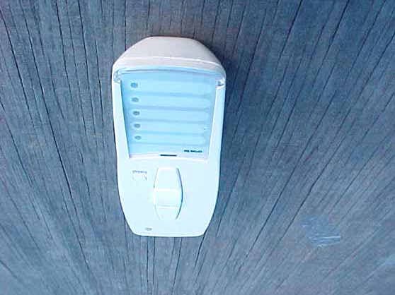
UFJ282400902
Jul 18, 2006Transmitter
Equipment Class
DXX - Part 15 Low Power Communication Device Transmitter