UM61831OPTICAL WIRELESS MOUSE
Juneng Electronics Technology Co., Ltd.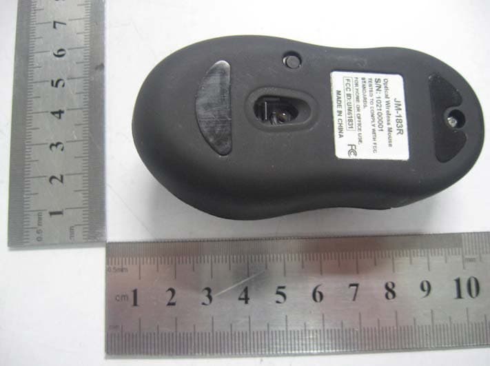
Click to zoom
Application Details
- Equipment Class
- DXX - Part 15 Low Power Communication Device Transmitter
- Date of Grant
- Sep 18, 2010
- Application Purpose
- Original Equipment
- Date of Application
- Sep 18, 2010
- Equipment Note
- OPTICAL WIRELESS MOUSE
- Frequency Range
- 27.04500000 - 27.04500000
- Country
- China
Documents & Files
Document Text
Text extracted from the exhibit documents filed with the FCC. Open a document above to read the original.
Users Manual
Optical Wireless Travel Mouse User’s Manual 2 INSTALLING BATTERIES: To properly install batteries into your Mouse, please follow the instructions below: 1. Remove the Battery Compartment Cover of your Mouse by pressing the silver release button in the middle of the mouse and slide the Battery Compartment Cover open. 2. Install two AAA Batteries into your Mouse following the battery orientation guide in the battery bay and then replace the Battery Compartment Cover back onto your Mouse until it securely locks. 3. After the AAA Batteries have been installed into your Mouse properly, the sensor LED inside your Mouse will light up. ESTABLISHING A CONNECTION: 1. Place the mouse in the effective area. 2. Press and hold the button at the bottom of your mouse for about 2 seconds, the LED indicator will flash rapidly and then turn off. 3. Your wireless optical mouse is now ready to be used. CHANGING THE SPEED OF YOUR MOUSE: To adjust the speed of the cursor or the scroll button features on your computer, please follow the instructions below: 3 NOTE: The screenshots show in this section are for demonstration only and your screen may look slightly different but with similar options. For Windows ® Open the “Control Panel”, and double-click the “Mouse” icon to open the mouse properties screen, and then select the “Pointer Options”. After you have made your changes; select “Apply”, and then “OK”. For Mac ® Open the “System Preferences”. At the System Preferences screen, click the “Keyboard & Mouse” icon to open the Keyboard & Mouse screen, and then select the “Mouse” tab and make your changes. Windows ® Mac ® FCC WARNING This device complies with Part 15 of the FCC Rules. Operation is subject to the following two conditions: (1) this device may not cause harmful interference, and (2) this device must accept any interference received, including interference that may cause undesired operation. NOTE 1: Any changes or modifications not expressly approved by the manufacturer could void the user’s authority to operate the equipment. NOTE 2: The manufacturer is not responsible for any radio or TV interference caused by unauthorized modifications to this equipment. Such modifications could void the user’s authority to operate the equipment.
Block Diagram
OPTICAL SENSOR
External Photos
JUNENG ELECTRONICS TECHNOLOGY CO., LTD. Model: JM-183R REPORT NO.: STR10098094I FCC PART 15.227 EXHIBIT 2 - EUT EXTERNAL PHOTOGRAPHS EUT View 1 EUT View 2
ID Label/Location Info
JUNENG ELECTRONICS TECHNOLOGY CO., LTD. Model: JM-183R REPORT NO.: STR10098094I FCC PART 15.227 EXHIBIT 1- PRODUCT LABELING Proposed FCC ID Label Format FCC ID: UM61831 Specifications : Text is Black in color and justified. Labels are printed in indelible ink on permanent adhesive silk-screened onto the EUT or shall be affixed at a conspicuous location on the EUT. Proposed Label Location on EUT FCC ID Label Location
ID Label/Location Info
JUNENG ELECTRONICS TECHNOLOGY CO., LTD. Model: JM-183R REPORT NO.: STR10098094I FCC PART 15.227 EXHIBIT 1- PRODUCT LABELING Proposed FCC ID Label Format FCC ID: UM61831 Specifications : Text is Black in color and justified. Labels are printed in indelible ink on permanent adhesive silk-screened onto the EUT or shall be affixed at a conspicuous location on the EUT. Proposed Label Location on EUT FCC ID Label Location
Internal Photos
JUNENG ELECTRONICS TECHNOLOGY CO., LTD. Model: JM-183R REPORT NO.: STR10098094I FCC PART 15.227 EXHIBIT 3 - EUT INTERNAL PHOTOGRAPHS EUT Housing and Board View Solder Board-Component View 1 JUNENG ELECTRONICS TECHNOLOGY CO., LTD. Model: JM-183R REPORT NO.: STR10098094I FCC PART 15.227 Solder Board-Component View 2
Operational Description
Wireless Mouse Transmitter Circuit Description a. U2-3101 is the integration of wireless controlling IC and optical IC. The optical part of 3101 transform the imaging of the mouse moving to the electronic signal, and then send to the controlling IC; the signal transmit from the antenna after loaded by the external via RF at 27.045 MHz. b. When the optical part of IC-3101 is working, the MCU will output the controlling signal Q6 from the PIN 5 to control the brightness of D1. c. U1-EV856P11H is the key control IC with a clock signal of the frequency 6MHz as base clock signal, and to control the RF signal output, the RF signal of the frequency 27.045MHz is generated by the RF circuit with a oscillator of the 13.5225MHz. d. The work voltage is DC 3.0V by 2*AAA battery.
Test Setup Photos
JUNENG ELECTRONICS TECHNOLOGY CO., LTD. Model: JM-183R REPORT NO.: STR10098094I FCC PART 15.227 EXHIBIT 4 - TEST SETUP PHOTOGRAPHS Radiation Emission Test Setup (30MHz to 1GHz) Radiation Emission Test Setup (Below 30MHz)
Contact Information
Applicant
Halley Chen(General Manager)
Test Firm
SEM.Test Compliance Service Co., Ltd.Jandy So
Technical Specifications
| # | Rule Parts | Frequency Range | Power Output |
|---|---|---|---|
| 1 | 15C | 27.045 MHz - 27.045 MHz | - |
Other Applications from Juneng Electronics Technology Co., Ltd.
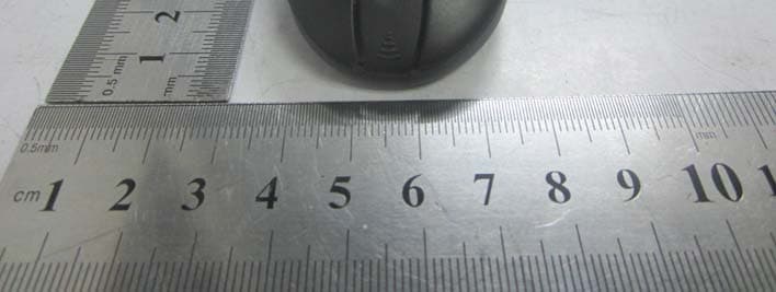
UM61833
Dec 11, 20122.4G WIRELESS MOUSE
Equipment Class
DXX - Part 15 Low Power Communication Device Transmitter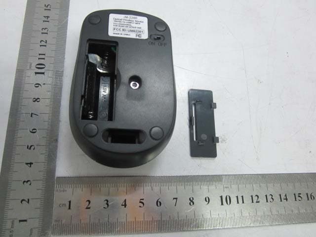
UM62281
Dec 25, 2011Optical Wireless Mouse
Equipment Class
DXX - Part 15 Low Power Communication Device Transmitter
UM60311
Nov 14, 2011OPTICAL WIRELESS MOUSE
Equipment Class
DXX - Part 15 Low Power Communication Device Transmitter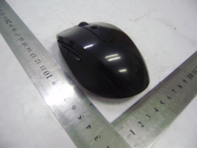
UM68601
Aug 02, 2011Optical Wireless Mouse
Equipment Class
DXX - Part 15 Low Power Communication Device Transmitter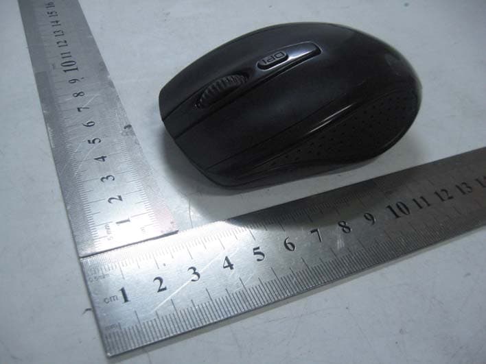
UM62291
May 22, 2011OPTICAL WIRELESS MOUSE
Equipment Class
DXX - Part 15 Low Power Communication Device Transmitter