UOU80E00008612DECT Handset
Mitel Deutschland GmbH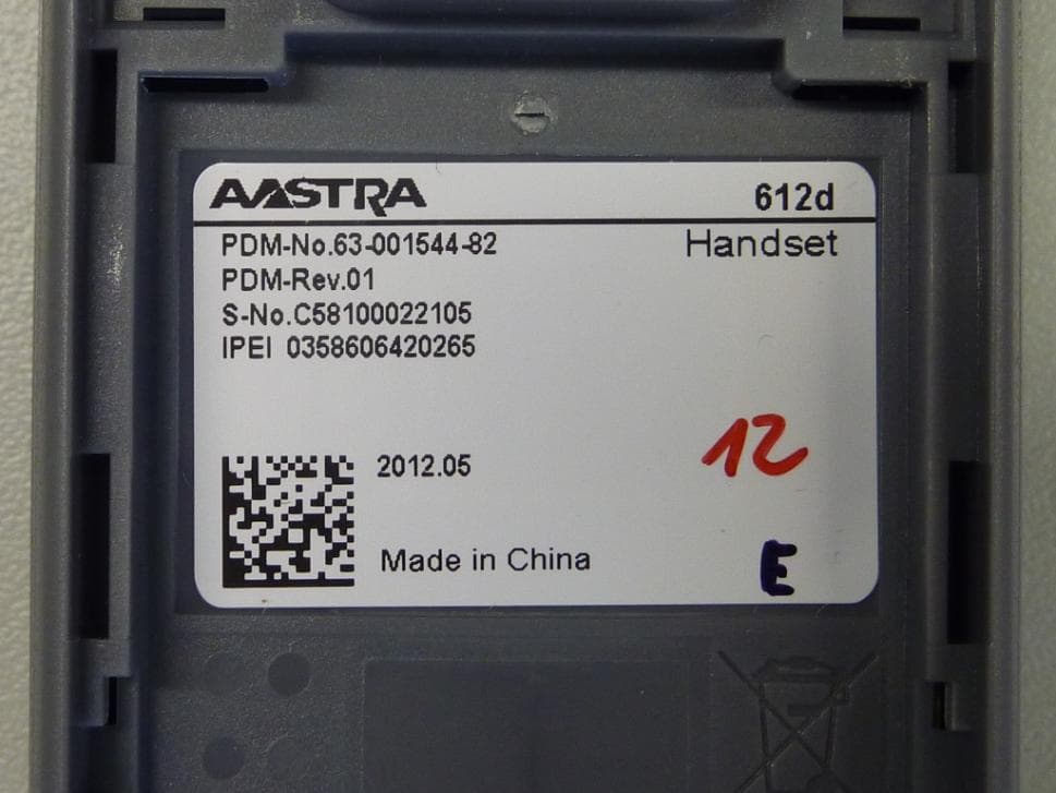
Click to zoom
Application Details
- Equipment Class
- PUE - Part 15 Unlicensed PCS portable Tx held to ear
- Date of Grant
- Sep 30, 2012
- Application Purpose
- Original Equipment
- Date of Application
- Sep 30, 2012
- Equipment Note
- DECT Handset
- Frequency Range
- 1921.53600000 - 1928.44800000
- Company
- Mitel Deutschland GmbH
- Country
- Germany
Documents & Files
Document Text
Text extracted from the exhibit documents filed with the FCC. Open a document above to read the original.
Users Manual
Top of folded document (german) Top of folded document (german) 105 mm 148.5 mm perforate perforateperforate 4 perforate 2 perforate perforate 1 3 5 6 crop , fold and perforate marks for QUG Aastra 600c/d Aastra 612d Désignation du document • N° de document: eud-1467 / 1.1 • Copyright © 05.2012 Aastra Technologies Limited Informations générales Votre appareil vous a été livré avec un mode d'emploi succinct contenant des indications de sécurité et, selon les circonstances, d'autres infor- mations spécifiques à l'appareil. Vous trouverez ce document ainsi que d'autres concernant votre appareil sur www.aastra.com ou ➃: www.aastra.com/docfinder. Systèmes de communication Votre téléphone peut être exploité sur différents systèmes de communication, raison pour laquel- le son utilisation est différente selon le système. La disponibilité des fonctions, caractéristiques, affectations de touches et produits dépend éga- lement du système de communication. Cochez ci-après votre système de communication : To u c h e s Symboles d’affichage (sélection) Français Système ➀Aastra 5000 ❏, Aastra X Series ❏, NeXspan ❏ ➁ Aastra 800 ❏, OpenCom 100 ❏, OpenCom 1000 ❏ ➂SIP-DECT® ❏ ➃Aastra 400 ❏, Aastra IntelliGate ❏ ➄MX-ONE SIP-DECT® ❏ Touche de prise de ligne : • Etablir la communication. • Touche de fonction R. Liste de répétition de la numérota- tion : •➀/➁/➂/➄: Appuyer longuement sur la touche de prise de ligne. •➃ : Appuyer sur la touche de prise de ligne. Touche de fin : • Fin de l'appel. • Quitter l'éditeur de texte sans effec- tuer de modifications. • Dans le menu : Retour à l'état de re- pos. • Appuyer longuement : Activer/dé- sactiver le téléphone. Touche de haut-parleur : Activer/dé- sactiver le mode mains libres. Touches afficheur : Exécuter la fonc- tion affichée à l'aide de la touche. To u c h e s d e n av ig a t ion : • Dans le menu : Défiler en avant et en arrière. • Dans des listes : Naviguer. • Au repos : Appels des fonctions af- fectées. Touche de correction : Effacer le der- nier caractère ou reculer dans le menu. Touches latérales "Plus / Moins" : Ré- g ler le volume d 'écoute de l a comm u- nication en cours. Touche Etoile : Appuyer longuement pour activer/désactiver la tonalité de sonnerie. ➂/➄: Changer entre majuscules et minuscules et entre chiffres et lettres. Touche Dièse : Appuyer longuement pour activer le verrouillage des tou- ches. Qualité de la liaison radio (4 colonnes : bon, 1 colonne : mauvais) Etat de charge des accus Microphone désactivé Tonalité de sonnerie désactivée Autres options disponibles Nouveau message dans la boîte vo- cale ➀/➃ : Nouveaux messages textuels ➀/➃ : Messages textuels lus Aastra 612d Document designation • Document number: eud-1466 / 1.1 • Copyright © 05.2012 Aastra Technologies Limited General information Your device has been supplied with a quick user’s guide, safety information and, where applicable, with other device-specific information. You will find this and other documents for your device at www.aastra.com or ➃: www.aastra.com/docfinder. Communication systems Your telephone can be used with different com- munication systems; therefore, the operation dif- fers according to system. The availability of the functions, features, key assignments and products also depends on the communication system. Mark your communication system as follows: Keys Display symbols (selection) English System ➀Aastra 5000 ❏, Aastra X Series ❏, NeXspan ❏ ➁ Aastra 800 ❏, OpenCom 100 ❏, OpenCom 1000 ❏ ➂SIP-DECT® ❏ ➃Aastra 400 ❏, Aastra IntelliGate ❏ ➄MX-ONE SIP-DECT® ❏ Call key: • Set up a connection. •R-key function. Redial list: •➀/➁/➂/➄: Press and hold down the Call key. •➃: Press the Call key. End key: • Cut connection. • Exit editor without changes. • In a menu: Back to idle state. • Press and hold down: Activate/de- activate phone. Loudspeaker key: Activate/deacti- vate hands-free mode. Softkeys: Executes displayed func- tion above key. Navigation keys: • In a menu: Scroll forward and back- ward. •In a list: Navigate. • In idle: Call up stored functions. Correction key: Delete the last char- acter or go back one step in the menu. "Plus / Minus" side keys: Adjust cur- rent connection volume. Star key: Press and hold down to acti- vate/deactivate ring tone. ➂/➄: To switch between digits/let- ters and upper/lower case. Hash key: Press and hold down to lock keypad. Radio link quality (4 signal bars: good, 1 signal bar: bad) State of charge Microphone off Ring tone off More options available New message in the voice mailbox ➀/➃: New text messages ➀/➃: Read text messages Aastra 612d Dokumentbezeichnung • Dokumentnummer: eud-1466 / 1.1 • Copyright © 05.2012 Aastra Technologies Limited Allgemeine Informationen Ihr Gerät wurde mit einer Kurzbedienungsanlei- tung, mit Sicherheitshinweisen und unter Um- ständen mit weiteren gerätespezifischen Infor- mationen ausgeliefert. Sie finden diese und wei- tere Dokumente zu Ihrem Gerät auf www.aast- ra.com oder ➃: www.aastra.com/docfinder. Kommunikationssysteme Ihr Telefon kann an unterschiedlichen Kommuni- kationssystemen betrieben werden, daher ist die Handhabung je nach System unterschiedlich. Die Verfügbarkeit der Funktionen, Merkmale, Tasten- belegungen und Produkte ist ebenfalls vom Kommunikationssystem abhängig. Markieren Sie nachfolgend Ihr Kommunikations- system: Tas ten Anzeige-Symbole (Auswahl) Deutsch System ➀Aastra 5000 ❏, Aastra X Series ❏, NeXspan ❏ ➁ Aastra 800 ❏, OpenCom 100 ❏, OpenCom 1000 ❏ ➂SIP-DECT® ❏ ➃Aastra 400 ❏, Aastra IntelliGate ❏ ➄MX-ONE SIP-DECT® ❏ Gesprächstaste: • Verbindung aufbauen. • R-Tastenfunktion. Wahlwiederholungsliste: •➀/➁/➂/➄: Gesprächstaste lang drücken. •➃: Gesprächstaste drücken. Beendentaste: • Verbindung beenden. • Editor ohne Änderungen verlassen. • Im Menü: Zurück in Ruhezustand. • Lang drücken: Telefon ein-/aus- schalten. Lautsprechertaste: Freisprechen ein-/ ausschalten. Softkeys: Angezeigte Funktion über der Taste ausführen. Navigationstasten: • Im Menü: Vor- und zurückblättern. • In List…
Text truncated - open the document above for the full version.
Users Manual
Top of folded document (german) Top of folded document (german) 105 mm 148.5 mm 4 crop and fold marks for SI Aastra 600c/d 2 1 3 5 6 Consignes de sécurité (non applicable pour Aastra 650c) Informations réglementaires en matière de communications Notes FCC (USA uniquement) Cet appareil est conforme à la partie 15 des règles FCC. Son exploitation est soumise aux deux condi- tions suivantes: (1) Cet appareil ne doit causer aucune interféren- ce dommageable et (2) cet appareil doit tolérer toute interférence reçue à l'inclusion des interfé- rences susceptibles de causer une opération non désirée. Les modifications non expressément agrées par cette entreprise pourraient rendre caduque l'habi- litation de l'utilisateur à exploiter cet équipement. Nota: Cet équipement a été testé et jugé conforme aux limitations pour un appareil numérique de classe B en vertu de la partie 15 des règles FCC. Ces limitations ont été conçues pour garantir une pro- tection raisonnable contre les interférences dom- mageables dans les installations résidentielles. Cet équipement génère, utilise et peut rayonner des ondes radio et peut causer des interférences dom- mageables dans les communications par radio s'il n'est pas installé et utilisé conformément aux ins- tructions. Cependant, l'absence d'interférences dans une installation particulière n'est pas garan- tie. Si cet équipement perturbe de façon importan- te la réception de la radio ou de la télévision (inter- férences qui peuvent être déterminées en arrêtant et en remettrant l'appareil en marche), l'utilisateur est invité à tenter de corriger les interférences en prenant une ou plusieurs des mesures suivantes : • Réorienter ou déplacer l'antenne de réception. • Eloigner l'équipement du récepteur. • Raccorder l'équipement à une prise d'un circuit différent de celui auquel est raccordé le récepteur. • Consulter le revendeur ou un technicien radio/TV. Santé et sécurité Exposition aux signaux radio (RF) Votre téléphone sans fil est un émetteur-récep- teur radio. Il a été conçu pour ne pas dépasser les limitations en matière d'exposition aux ondes ra- dio établies par la Federal Communications Com- mission (FCC) du gouvernement des Etats-Unis. Ces limitations font partie de directives complètes et établissent des niveaux admissibles d'énergie RF pour l'ensemble de la population. Ces directi- ves sont basées sur des normes de sécurité éta- blies par des organes de normalisation américains et internationaux. Ces normes intègrent une im- portante marge de sécurité censée garantir la sé- curité de toute personne, quels que soient son âge et son état de santé. Cet appareil et son antenne ne doivent pas être installés ou exploités conjointement avec d'autres antennes ou émetteurs. Cet appareil a démontré sa compatibilité avec le degré d'absorption spécifique localisé, aux limita- tions pour l'exposition non contrôlée de l'environ- nement / de la population spécifiée dans les nor- mes ANSI / IEEE C95.1-1992 et a été testé en conformité avec les procédures de mesure spéci- fiées dans le bulletin FCCT/OET 67 Supplément C (2001) et IEEE 1528-2003. Industrie Canada (Canada uniquement) L'exploitation de cet appareil est soumise aux deux conditions suivantes: (1) Cet appareil ne doit causer aucune interférence et (2) cet appareil doit tolérer toute interférence reçue à l'inclusion des interférences susceptibles de causer une opéra- tion non désirée. La confidentialité des communications risque de ne pas être garantie lorsque vous utilisez ce téléphone. Exposition aux ondes radio (RF): Votre téléphone sans fil est un émetteur-récep- teur radio. Il a été conçu pour ne pas dépasser les limitations en matière d'exposition aux ondes ra- dio émises par le Ministère de la Santé (Canada,) Code de sécurité 6. Ces limitations font partie de directives complètes et établissent des niveaux admissibles d'énergie RF pour l'ensemble de la population. Ces directives sont basées sur des normes de sécurité établies par des organes de normalisation internationaux. Ces normes intè- grent une importante marge de sécurité censée garantir la sécurité de toute personne, quels que soient son âge et son état de santé. Cet appareil et son antenne ne doivent pas être installés ou exploités conjointement avec d'autres antennes ou émetteurs. Cet appareil a démontré sa compatibilité avec le de- gré d'absorption spécifique localisé, aux limitations pour l'exposition non contrôlée de l'environnement / du public spécifiée dans les normes ANSI / IEEE C95.1-1992 et a été testé en conformité avec les pro- cédures de mesure spécifiées dans IEEE 1528-2003. FR Français Indications de sécurité (Aastra 600c/d) Informations pour l'utilisateur Votre appareil vous a été livré avec un mode d'em- ploi succinct contenant des indications de sécuri- té et, selon les circonstances, d'autres informa- tions spécifiques à l'appareil. Vous pouvez télé- charger ce document ainsi que d'autres concer- nant votre appareil depuis www.aastra.com. Vous trouverez d'autres informations sur votre appareil dans les documents ou sur le site de votre reven- deur. Il est de votre devoir de vous informer de l'étendue des fonctions, de la desserte et de l'em- ploi adéquat de l'appareil. • Vérifiez si vous avez toutes les informations d’utilisateur correspondant à votre appareil, si celles-ci correspondent à la version de votre ap- pareil et si elles sont à jour. • Lisez attentivement les informations d’utilisa- teur avant de mettre votre appareil en service. • Conservez ces informations à un endroit bien accessible et consultez-les si vous avez des dou- tes quant au maniement de l'appareil. • Ne remettez votre appareil à des tiers que conjointement aux informations d’utilisateur. L'inobservation de ces prescriptions peut occasionner des dangers et violer la législa- tion en vigueur. Appareils médicaux Vérifiez si l’utilisation d’équipements de télé- communication (téléphones sans fil) est autori- sée à proximité d’appareils médicaux. Veuillez suiv…
Text truncated - open the document above for the full version.
External Photos
Test report no.: 1-4722/12-06-02 2012-06-13 Page 59 of 67 An nex B: Exte rnal Pho tog rap hs o f t he EU T Photo 1: Photo 2: Test report no.: 1-4722/12-06-02 2012-06-13 Page 60 of 67 Photo 3: Photo 4: Test report no.: 1-4722/12-06-02 2012-06-13 Page 61 of 67 Photo 5: Photo 6:
ID Label/Location Info
System: MS Word edited: 28.08.2012 3033hae Handset 612d Format: A4 checked: Aastra Deutschland GmbH released: 28.08.2012 3612eber Document number Rev. 80E00008AAA-Y90-LB000 02 „Copyright reserved“ Shee t: 1 of 2 filename control picture scale 1:1 location ¦ assembly label blank size (mm) 80E00008AAA_Y90_LB000_02_equipment.lab Equipment Printed label must fulfill the durability requirements according EN60950 Contact pressure: 10N – 15N 42-001333-00 31.8 x 20.6 80E00008AAA_Y90_LB000_02_box side.lab Box side 42-001461-00 30.0 x 100.0 80E00008AAA_Y90_LB000_02_box top.lab Box top 42-001565-00 90.0 x 90.0 5a) 4a) 2a) 1a) 4) 5) 2) 6) 1a) 4a) 3a) 7) 2a) System: MS Word edited: 28.08.2012 3033hae Handset 612d Format: A4 checked: Aastra Deutschland GmbH released: 28.08.2012 3612eber Document number Rev. 80E00008AAA-Y90-LB000 02 „Copyright reserved“ Shee t: 2 of 2 Notes for decoding: 1a) Production date / Repair date YYYY.MM = (Example 2012.06) Production Date or Datecode from the Supplier YY / MM Rx = (Example 12 / 03 Rx) Repair date code from the supplier (for repair centre) Repair centre identification 2a) Consecutive numbers S-No. = digitally coded data, according document PA-001013-00 2’ Year and month of Manufacture (EN 60062) 1’ Vendor identification 2’ Product and Brand Type 6’ Serial number (000001 - 999999) same output Barcode 6), 7) 1’ Check digit (Handset 612d) xx810xxxxxxx 3a) IPEI number IPEI = IPEI - No is taken from the IPEI-number-pool after final test 4a) PDM Rev. PDM Rev. = According current PDM Revision 5a) GIM / ERP Part number coding (fix) 2’ Part Category 1’ Sub Class 5’ Number 1’ Variant 2’ Market version 1’ Functional revision (Handset 612d) 80E00008AAA-Y Barcodes & Datamatrix: Pos Code Typ Detail (Resolution) Code content fix data content Remarks 2) 128 Auto M = 13 mil / 0.3302 mm constant QTY 1 Quantity 4) EAN-13 M = 13 mil / 0.3302 mm constant 763001381988 *(2) 76 Country Code ( Switzerland ) 300138 Global Company Prefix 1988 Range of allocable Numbers * (2) (check digit) 5) 128 Auto M = 10 mil / 0.254 mm variable 80E00008AAA-Y ERP no. handset 612d box 6) Data Matrix ECC200 Auto M = 25 mil / 0.10 mm constant constant variable 63-001544-90; 80E00008AAA-Y; xx810xxxxxxx PDM no. handset 612d ERP no. handset box 612d serial no. handset 612d, same output 2a) (The separator must be a semikolon, without blanks between the different numbers) 7) Data Matrix ECC200 Auto M = 15 mil / 0.3810 mm constant variable 63-001544-90; xx810xxxxxxx PDM no. handset 612d and serial no. handset 612d, same output 2a) (The separator must be a semikolon, without blanks between the different numbers) Symbols: Symbols File names Symbols File names aastra_black.jpg ce.jpg
Internal Photos
Test report no.: 1-4722/12-06-02 2012-06-13 Page 62 of 67 An nex C: In ter nal Pho tog raphs o f t h e EUT Photo 1: Photo 2: Test report no.: 1-4722/12-06-02 2012-06-13 Page 63 of 67 Photo 3: Photo 4: Test report no.: 1-4722/12-06-02 2012-06-13 Page 64 of 67 Photo 5: Photo 6:
RF Exposure Info
Page 1 of 43 TEST REPORT Test Report No.: 1-4722/12-06-04-A Testing Laboratory Applicant CETECOM ICT Services GmbH Untertürkheimer Straße 6 – 10 66117 Saarbrücken/Germany Phone: + 49 681 5 98 - 0 Fax: + 49 681 5 98 - 9075 Internet: http://www.cetecom.com e-mail: [email protected] Accredited Test Laboratory: The testing laboratory (area of testing) is accredited according to DIN EN ISO/IEC 17025 (2005) by the Deutsche Akkreditierungsstelle GmbH (DAkkS) The accreditation is valid for the scope of testing procedures as stated in the accreditation certificate with the registration number: D-PL-12076-01-01 Aastra Deutschland GmbH Zeughofstr. 1 10997 Berlin/GERMANY Phone: +49 30 6104-0 Contact: Gerhard Hofmann e-mail: [email protected] Phone: +49 30 6104-5329 Fax: +49 30 6104-5157 Manufacturer Aastra Deutschland GmbH Zeughofstr. 1 10997 Berlin/GERMANY Test Standard/s IEEE 1528-2003 Recommended Practice for Determining the Peak Spatial-Average Specific Absorption Rate (SAR)in the Human Head from Wireless Communications Devices: Measurement Techniques OET Bulletin 65 Supplement C Evaluating Compliance with FCC Guidelines for Human Exposure to Radiofrequency Electromagnetic Fields RSS-102 Issue 4 Radio Frequency Exposure Compliance of Radiocommunication Apparatus (All Frequency Bands) For further applied test standards please refer to section 3 of this test report. Test Item Kind of test item: DECT Portable Part Device type: portable device Model name: 612d S/N serial number: C58100008058 FCC-ID: UOU80E00008612 IC: 1884E-80E00008612 Hardware status: 63-001544-82 Software status: 1.01 Frequency: see technical details Antenna: integrated antenna Battery option: Li-ion battery 3.7V / 880mAh Accessories: --- Test sample status: production unit Exposure category: general population / uncontrolled environment This test report is electronically signed and valid without handwriting signature. For verification of the electronic signatures, the public keys can be requested at the testing laboratory. Test Report authorised: Test performed: Thomas Vogler Oleksandr Hnatovskiy Senior Testing Manager Testing Manager Test report no.: 1-4722/12-06-04-A Page 2 of 43 1 Table of contents 1 Table of contents ....................................................................................................................................... 2 2 General information .................................................................................................................................. 3 2.1 Notes and disclaimer ..................................................................................................................... 3 2.2 Application details ......................................................................................................................... 3 2.3 Statement of compliance ............................................................................................................... 3 2.4 Technical details............................................................................................................................. 4 3 Test standards/ procedures references .................................................................................................. 5 3.1 RF exposure limits ......................................................................................................................... 6 4 Summary of Measurement Results ......................................................................................................... 7 5 Test Environment ...................................................................................................................................... 7 6 Test Set-up ................................................................................................................................................. 8 6.1 Measurement system ..................................................................................................................... 8 6.1.1 System Description ................................................................................................................ 8 6.1.2 Test environment ................................................................................................................... 9 6.1.3 Probe description ................................................................................................................... 9 6.1.4 Phantom description ............................................................................................................ 10 6.1.5 Device holder description .................................................................................................... 10 6.1.6 Scanning procedure ............................................................................................................ 11 6.1.7 Spatial Peak SAR Evaluation .............................................................................................. 12 6.1.8 Data Storage and Evaluation............................................................................................... 13 6.1.9 Tissue simulating liquids: dielectric properties .................................................................... 15 6.1.10 Tissue simulating liquids: parameters ................................................................................. 16 6.1.11 Measurement uncertainty evaluation for system check ...................................................... 17 6.1.12 Measurement uncertainty evaluation for system validation ................................................ 18 6.1.13 System check ...................................................................................................................... 19 6.1.14 System check procedure ..................................................................................................... 19 7 Detailed Test Results .......................................................................................................................…
Text truncated - open the document above for the full version.
RF Exposure Info
Page 1 of 29 Annex E Appendix to Test Report No.: 1-4722/12-06-04-A Testing Laboratory CETECOM ICT Services GmbH Untertürkheimer Straße 6 – 10 66117 Saarbrücken/Germany Phone: + 49 681 5 98 - 0 Fax: + 49 681 5 98 - 9075 Internet: http://www.cetecom.com e-mail: [email protected] Accredited Test Laboratory: The testing laboratory (area of testing) is accredited according to DIN EN ISO/IEC 17025 (2005) by the Deutsche Akkreditierungsstelle GmbH (DAkkS) The accreditation is valid for the scope of testing procedures as stated in the accreditation certificate with the registration number: D-PL-12076-01-01 Appendix with Calibration data, Phantom certificate and system validation information Annex E to Test report no.: 1-4722/12-06-04-A Page 2 of 29 1 Table of contents 1 Table of contents ....................................................................................................................................... 2 2 Calibration report “Probe ET3DV6” ......................................................................................................... 3 3 Calibration report “1900 MHz System validation dipole” .................................................................... 14 4 Calibration certificate of Data Acquisition Unit (DAE) ........................................................................ 22 5 Certificate of “SAM Twin Phantom V4.0/V4.0C’’ ................................................................................. 23 6 Application Note System Performance Check ..................................................................................... 24 6.1 Purpose of system performance check ..................................................................................... 24 6.2 System Performance check procedure ...................................................................................... 24 6.3 Uncertainty Budget ...................................................................................................................... 25 6.4 Power set-up for validation ......................................................................................................... 28 6.5 Laboratory reflection ................................................................................................................... 29 6.6 Additional system checks ........................................................................................................... 29 Annex E to Test report no.: 1-4722/12-06-04-A Page 3 of 29 2 Calibration report “Probe ET3DV6” Annex E to Test report no.: 1-4722/12-06-04-A Page 4 of 29 Annex E to Test report no.: 1-4722/12-06-04-A Page 5 of 29 Annex E to Test report no.: 1-4722/12-06-04-A Page 6 of 29 Annex E to Test report no.: 1-4722/12-06-04-A Page 7 of 29 Annex E to Test report no.: 1-4722/12-06-04-A Page 8 of 29 Annex E to Test report no.: 1-4722/12-06-04-A Page 9 of 29 Annex E to Test report no.: 1-4722/12-06-04-A Page 10 of 29 Annex E to Test report no.: 1-4722/12-06-04-A Page 11 of 29 Annex E to Test report no.: 1-4722/12-06-04-A Page 12 of 29 Annex E to Test report no.: 1-4722/12-06-04-A Page 13 of 29 Annex E to Test report no.: 1-4722/12-06-04-A Page 14 of 29 3 Calibration report “1900 MHz System validation dipole” Annex E to Test report no.: 1-4722/12-06-04-A Page 15 of 29 Annex E to Test report no.: 1-4722/12-06-04-A Page 16 of 29 Annex E to Test report no.: 1-4722/12-06-04-A Page 17 of 29 Annex E to Test report no.: 1-4722/12-06-04-A Page 18 of 29 Annex E to Test report no.: 1-4722/12-06-04-A Page 19 of 29 Annex E to Test report no.: 1-4722/12-06-04-A Page 20 of 29 Annex E to Test report no.: 1-4722/12-06-04-A Page 21 of 29 Annex E to Test report no.: 1-4722/12-06-04-A Page 22 of 29 4 Calibration certificate of Data Acquisition Unit (DAE) Annex E to Test report no.: 1-4722/12-06-04-A Page 23 of 29 5 Certificate of “SAM Twin Phantom V4.0/V4.0C’’ Annex E to Test report no.: 1-4722/12-06-04-A Page 24 of 29 6 Application Note System Performance Check 6.1 Purpose of system performance check The system performance check verifies that the system operates within its specifications. System and operator errors can be detected and corrected. It is recommended that the system performance check is performed prior to any usage of the system in order to guarantee reproducible results. The measurement of the Specific Absorption Rate (SAR) is a complicated task and the result depends on the proper functioning of many components and the correct settings of many parameters. Faulty results due to drift, failures or incorrect parameters might not be recognized, since they often look similar in distribution to the correct ones. The Dosimetric Assessment System DASY4 incorporates a system performance check procedure to test the proper functioning of the system. The system performance check uses normal SAR measurements in a simplified setup (the flat section of the SAM Twin Phantom) with a well characterized source (a matched dipole at a specified distance). This setup was selected to give a high sensitivity to all parameters that might fail or vary over time (e.g., probe, liquid parameters, and software settings) and a low sensitivity to external effects inherent in the system (e.g., positioning uncertainty of the device holder). The system performance check does not replace the calibration of the components. The accuracy of the system performance check is not sufficient for calibration purposes. It is possible to calculate the field quite accurately in this simple setup; however, due to the open field situation some factors (e.g., laboratory reflections) cannot be accounted for. Calibrations in the flat phantom are possible with transfer calibration methods, using either temperature probes or calibrated E-field probes. The system performance check also does not test the system performance for arbitrary field situations encountered during real measurements of mobile phones. These checks are performed at SPEAG by testing the components under vario…
Text truncated - open the document above for the full version.
Test Report
2012-06-13 Page 1 of 67 TEST REPORT Test Report No.: 1-4722/12-06-02 Testing Laboratory Applicant CETECOM ICT Services GmbH Untertürkheimer Straße 6 – 10 66117 Saarbrücken/Germany Phone: + 49 681 5 98 - 0 Fax: + 49 681 5 98 - 9075 Internet: http://www.cetecom.com e-mail: [email protected] Accredited Test Laboratory: The testing laboratory (FCC part 15 D) is accredited according to DIN EN ISO/IEC 17025 (2005) by the Deutsche Akkreditierungsstelle GmbH (DAkkS) The accreditation is valid for the scope of testing procedures as stated in the accreditation certificate with the registration number: D-PL-12076-01-01 Aastra Deutschland GmbH Zeughofstr. 1 10997 Berlin Germany Phone: + 49 30 6104-2007 Fax: + 49 30 6104-5157 Contact: Mr. Gerhard Hofmann e-mail: [email protected] Phone: + 49 30 6104-5329 Manufacturer Aastra Deutschland GmbH Zeughofstr. 1 10997 Berlin, Germany Test Standard/s FCC Part 15, subpart D Isochronous UPCS Device 1920 – 1930 MHz Industry Canada RSS-213, Issue 2 2 GHz Licence-exempt Personal Communication Service Devices (LE-PCS) Test Item Kind of test item: DECT Portable Part Model name: 612d FCC ID: UOU80E00008612 IC: 1884E-80E00008612 S/N serial number: / HW hardware status: 63-001544-82 SW software status: 1.01 Frequency [MHz]: 1920 -1930 Type of Modulation: Digital (Gaussian Frequency Shift Keying) Number of channels: 5 RF Channels, 5x12 = 60 TDMA Duplex Channels Antenna: 1 permanently attached ג/4 antenna Power Supply: 3.7 V DC Temperature Range: -20°C to 50°C Test Report authorised: Test performed: p.o. 2012-06-13 Wolf, Joachim 2012-06-13 Lenjoint, Marco Senior Consultant Testing Manager Test report no.: 1-4722/12-06-02 2012-06-13 Page 2 of 67 1 Table of contents 1 Table of contents ....................................................................................................................................... 2 2 General information .................................................................................................................................. 4 2.1 Notes and disclaimer ..................................................................................................................... 4 2.2 Application details ......................................................................................................................... 4 3 Test standard/s: ......................................................................................................................................... 4 4 Test Environment ...................................................................................................................................... 5 5 Test Item .............................................................................................…
Text truncated - open the document above for the full version.
Contact Information
Applicant
Henrik Wagener
Test Firm
cetecom advanced GmbHGerald Schmidt
Technical Specifications
| # | Rule Parts | Frequency Range | Power Output | Tolerance |
|---|---|---|---|---|
| 1 | 15D | 1.92 GHz - 1.93 GHz | 97.00 mW | 4.3800000000 ppm |
Other Applications from Mitel Deutschland GmbH
UOU80E00009622
Sep 30, 2012DECT Handset
Equipment Class
JBP - Part 15 Class B Computing Device Peripheral
UOU68637RFP35U-01
Mar 04, 2012DECT Base station
Equipment Class
PUB - Part 15 Unlicensed PCS Base Station
UOU69135RFP32U-01
Dec 19, 2006RFP 32 US
Equipment Class
PUB - Part 15 Unlicensed PCS Base Station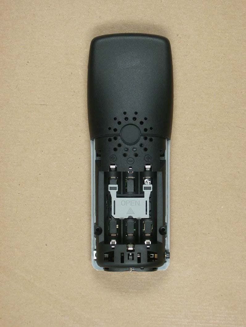
UOU69126OP27DS-01
Dec 17, 2006Aastra Phone 142 US
Equipment Class
JBP - Part 15 Class B Computing Device Peripheral