UXS-IPM165K-Band Transceiver
InnoSenT GmbH
Click to zoom
Application Details
- Equipment Class
- FDS - Part 15 Field Disturbance Sensor
- Date of Grant
- Nov 14, 2013
- Application Purpose
- Original Equipment
- Date of Application
- Nov 14, 2013
- Equipment Note
- K-Band Transceiver
- Frequency Range
- 24075.00000000 - 24175.00000000
- Company
- InnoSenT GmbH
- Country
- Germany
Documents & Files
Document Text
Text extracted from the exhibit documents filed with the FCC. Open a document above to read the original.
Users Manual
and manufactured in Germany designed Innovation in Radar Technology USER MANUAL CONFIDENTIAL AND PROPRIETARY The information contained in this document shall remain the sole and exclusive property of InnoSenT GmbH and shall not be disclosed by the recipient to third parties without prior consent of InnoSenT in writing. Page 1 USER MANUAL IPM-165_F Version 8.3 PRODUCT FAMILY APPLICATIONS FEATURES: DESCRIPTION ADDITIONAL INFORMATION InnoSenT Standard Product. Changes will not be notified as long as there is no influence on form, fit and within this datasheet specified function of the product. RoHS-INFO This product is compliant to the restriction of hazardous substances (RoHS - European Union directive 2011/65/EU). CERTIFICATES InnoSenT GmbH has established and applies a quality system for: development, production and sales of radar sensors for industrial and automotive sensors. Version The IPM-165 is a 24GHz Doppler module with an asymmetrical wide beam for detection of moving objects. Low power consumption components are quickly enabled supporting duty cycles for battery or solar panel operation. Certified and approved according to • ETSI EN 300 440 • FCC part 15.245 8.3 - 24.10.2013 IPM-165_F Low Cost K-Band Transceiver • Security applications • Door openers • Industrial applications Movement Velocity Direction Presence Distance Angle »radar-based motion detector working in the 24GHz - ISM - Band »available in different frequency ranges for worldwide use »advanced LCO-oscillator with low current consumption »split transmit and receive path for maximum gain »very compact outline dimensions Innovation in Radar Technology CONFIDENTIAL AND PROPRIETARY The information contained in this document shall remain the sole and exclusive property of InnoSenT GmbH and shall not be disclosed by the recipient to third parties without prior consent of InnoSenT in writing. Page 2 USER MANUAL IPM-165_F Version 8.3 PARAMETERCONDITIONSSYMBOLMINTYPMAXUNITS Oscillator transmit frequency 1 US-frequency band@ 25°Cf F 24.07524.175GHz output powerP out 16dBm temperature driftΔf-1MHz/°C Receiver IF-outputvoltage offset-300300mV Signal level 2 category A563855mV P-P category B856117 7mV P-P category C117 81819mV P-P Noise level 2 R116mV Antenna Pattern full beam width @ -3dBazimuthhorizontal80° elevationvertical35° side-lobe suppressionazimuthhorizontal12dB elevationvertical13dB Antenna gain9.5dBi Power supply supply voltageV CC 4.755.005.25V supply currentI CC 3040mA Environment operating temperatureT OP -20+60°C storage temperatureT storage -20+60°C Mechanical Outlines outline dimensions height length width 25 25 7 (12.7) mm 1 Details to the frequency bands you can find in Annex A 2 Relative output signal level and noise is measured at room temperature in a dedicated InnoSenT test setup ELECTRICAL CHARACTERISTICS ESD Info This InnoSenT sensor is sensitive to damage from ESD. Normal precautions as usually applied to CMOS devices are sufficient when handling the device. Touching the signal output pins has to be avoided at any time before soldering or plugging the device into a motherboard. Innovation in Radar Technology CONFIDENTIAL AND PROPRIETARY The information contained in this document shall remain the sole and exclusive property of InnoSenT GmbH and shall not be disclosed by the recipient to third parties without prior consent of InnoSenT in writing. Page 3 USER MANUAL IPM-165_F Version 8.3 PIN #DESCRIPTIONIN / OUTCOMMENT 1V CC inputsupply voltage (4.75 - 5.25V) 2IF1outputsignal I(nphase) 3GNDinputanalog ground INTERFACE The sensor provides a 2.54mm grid, single row pin header (square pin 0.635mm) MECHANICAL OUTLINES PIN 1 10.50 1.25 1.90 6.60 +1.00- 0.20 25.00 + 0.20 - 0.20 25.00 + 0.20 - 0.20 20.20 + 0.20 - 0.20 20.20 + 0.20 - 0.20 12.70 PIN 1 PIN 1 9.96 2.54 antenna all dimensions in mm backside side viewbottom view top view NOTICE: This device complies with Part 15 of the FCC Rules [and with Industry Canada licence-exempt RSS standard(s)]. Operation is subject to the following two conditions: (1) this device may not cause harmful interference, and (2) this device must accept any interference received, including interference that may cause undesired operation. Le présent appareil est conforme aux CNR d'Industrie Canada applicables aux appareils radio exempts de licence. L'exploitation est autorisée aux deux conditions suivantes: (1) l'appareil ne doit pas produire de brouillage, et (2) l'utilisateur de l'appareil doit accepter tout brouillage radioélectrique subi, même si le brouillage est susceptible d'en compromettre le fonctionnement. NOTICE: Changes or modifications made to this equipment not expressly approved by (manufacturer name) may void the FCC authorization to operate this equipment. Text for User Manual (blue cursive text) For a Class A digital device or peripheral, the instructions furnished the user shall include the following or similar state- ment, placed in a prominent location in the text of the manual: NOTE: This equipment has been tested and found to comply with the limits for a Class A digital device, pursuant to Part 15 of the FCC Rules. These limits are designed to provide reasonable protection against harmful interference when the equip- ment is operated in a commercial environment. This equipment generates, uses, and can radiate radio frequency energy and, if not installed and used in accordance with the instruction manual, may cause harmful interference to radio commu- nications. Operation of this equipment in a residential area is likely to cause harmful interference in which case the user will be required to correct the interference at his own expense. Innovation in Radar Technology Page 4 USER MANUAL IPM-165_F Version 8.3 InnoSenT GmbH Am Rödertor 30 97499 Donnersdorf GERMANY Tel.: E-Mail: URL: +49 (0) 9528 - 9518 - 0 [email protected] www.innosent.de FCC approval Changes or modifications made to the equipment not expressly approved by InnoSenT GmbH may void the FCC / IC authori…
Text truncated - open the document above for the full version.
External Photos
Test report no.: 1-6308/13-01-02 2013-09-24 Page 25 of 28 Annex B External photographs of the EUT Photo 4: Photo 5:
ID Label/Location Info
- ID-LABEL / LOCATION INFO - CONFIDENTIAL IPM-165_F 24GHz-Doppler-Module Seite 1 von 2 14.11.2013 CONFIDENTIAL AND PROPRIETARY The information contained in this document is the exclusive property of InnoSenT GmbH and must not be disclosed by the recipient to third parties InnoSenT GmbH Am Roedertor 30 97499 Donnersdorf GERMANY Tel.: 0049-9528-9518-0 Fax.: 0049-9528-9518-99 Documentation for FCC / IC -approval - ID-Label / Location Info - Module : IPM-165_F for InnoSenT GmbH Am Roedertor 30 97499 Donnersdorf Germany - ID-LABEL / LOCATION INFO - CONFIDENTIAL IPM-165_F 24GHz-Doppler-Module Seite 2 von 2 14.11.2013 CONFIDENTIAL AND PROPRIETARY The information contained in this document is the exclusive property of InnoSenT GmbH and must not be disclosed by the recipient to third parties ID-Label / Location Info
Internal Photos
Test report no.: 1-6308/13-01-02 2013-09-24 Page 26 of 28 Annex C Internal photographs of the EUT Photo 6:
Test Report
2013-11-15 Page 1 of 28 TEST REPORT Test report no.: 1-6308/13-01-02-A Testing laboratory Applicant CETECOM ICT Services GmbH Untertuerkheimer Strasse 6 – 10 66117 Saarbruecken / Germany Phone: + 49 681 5 98 - 0 Fax: + 49 681 5 98 - 9075 Internet: http://www.cetecom.com e-mail: [email protected] Accredited Testing Laboratory: The testing laboratory (area of testing) is accredited according to DIN EN ISO/IEC 17025 (2005) by the Deutsche Akkreditierungsstelle GmbH (DAkkS) The accreditation is valid for the scope of testing procedures as stated in the accreditation certificate with the registration number: D-PL-12076-01-01 Area of Testing: Radio/Satellite Communications InnoSenT GmbH Am Rödertor 30 97499 Donnersdorf / GERMANY Phone: +49 9528 9518-0 Fax: +49 9528 9518-99 Contact: Christian Bömmel e-mail: [email protected] Phone: +49 9528 9518-72 Manufacturer InnoSenT GmbH Am Rödertor 30 97499 Donnersdorf / GERMANY Test standard/s 47 CFR Part 15 Title 47 of the Code of Federal Regulations; Chapter I; Part 15 - Radio frequency devices RSS - 210 Issue 8 Spectrum Management and Telecommunications Radio Standards Specification Licence-exempt Radio Apparatus (All Frequency Bands): Category I Equipment For further applied test standards please refer to section 3 of this test report. Test Item Kind of test item: K-Band Transceiver Model name: IPM-165_F FCC ID: UXS-IPM165 IC: 6902A-IPM165 Frequency: 24.075 GHz – 24.175 GHz Antenna: Integrated patch antenna Power supply: 5.00 V DC from power supply Temperature range: -40 °C to +85 °C This test report is electronically signed and valid without handwriting signature. For verification of the electronic signatures, the public keys can be requested at the testing laboratory. Test report authorised: Test performed: Karsten Geraldy Meheza Walla Senior Testing Manager Expert Test report no.: 1-6308/13-01-02-A 2013-11-15 Page 2 of 28 1 Table of contents 1 Table of contents............................................................................................................................................2 2 General information .......................................................................................................................................3 2.1 Notes and disclaimer ..........................................................................................................................3 2.2 Application details...............................................................................................................................3 3 Test standard/s ...............................................................................................................................................4 4 Test environment............................................................................................................................................4 5 Test item ..........................................................................................................................................................4 6 Test laboratories sub-contracted .................................................................................................................4 7 Summary of measurement results ...............................................................................................................5 8 RF measurement testing................................................................................................................................6 8.1 Description of test setup ....................................................................................................................6 8.1.1 Radiated measurements.............................................................................................................6 8.1.2 Additional comments ..................................................................................................................7 9 Measurement results......................................................................................................................................8 9.1 Field strength of emissions (wanted signal) ....................................................................................8 9.2 Occupied bandwidth (99% bandwidth) ...........................................................................................10 9.3 Field strength of emissions (radiated spurious) ............................................................................12 9.4 Conducted spurious emissions < 30 MHz ......................................................................................19 10 Test equipment and ancillaries used for tests ...................................................................................21 11 Observations .........................................................................................................................................22 Annex A Photographs of the test setup ......................................................................................................23 Annex B External photographs of the EUT.................................................................................................25 Annex C Internal photographs of the EUT ..................................................................................................26 Annex D Document history ..........................................................................................................................27 Annex E Further information........................................................................................................................27 Annex F Accreditation Certificate ...............................................................................................................28 Test report no.: 1-6308/13-01-02-A 2013-11-15 Page 3 of 28 2 General information 2.1 Notes and disclaimer The test results of this test report relate exclusively to the test item specified in this test report. CETECOM ICT Services GmbH do…
Text truncated - open the document above for the full version.
Test Setup Photos
Test report no.: 1-6308/13-01-02 2013-09-24 Page 23 of 28 Annex A Photographs of the test setup Photo 1: Photo 2: Test report no.: 1-6308/13-01-02 2013-09-24 Page 24 of 28 Photo 3:
Contact Information
Applicant
Robert Mock
Test Firm
Cetecom ICT Services GmbHRalf Hoehn
Technical Specifications
| # | Rule Parts | Frequency Range | Power Output |
|---|---|---|---|
| 1 | 15.245 | 24.07 GHz - 24.18 GHz | - |
Other Applications from InnoSenT GmbH
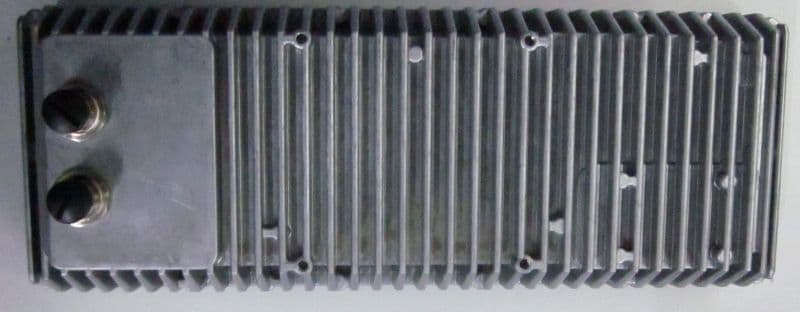
UXS-ITR-3800
May 29, 2023Stationary Traffic Monitoring
Equipment Class
DXX - Part 15 Low Power Communication Device Transmitter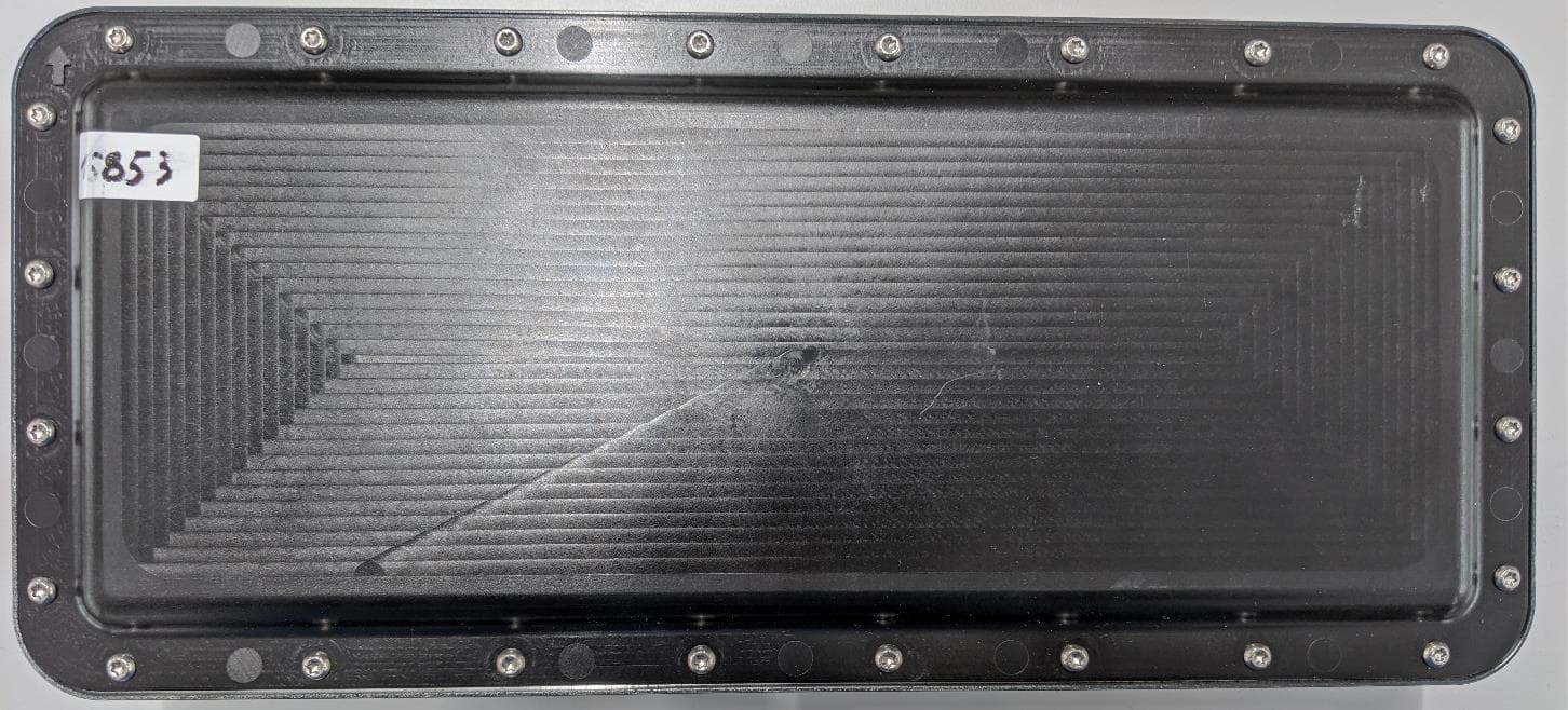
UXS-ISYS-5220
May 03, 2021K-Band Transceiver
Equipment Class
DXT - Part 15 Low Power Transceiver, Rx Verified
UXS-IVS979
Jan 14, 201324 GHz Doppler Module
Equipment Class
FDS - Part 15 Field Disturbance Sensor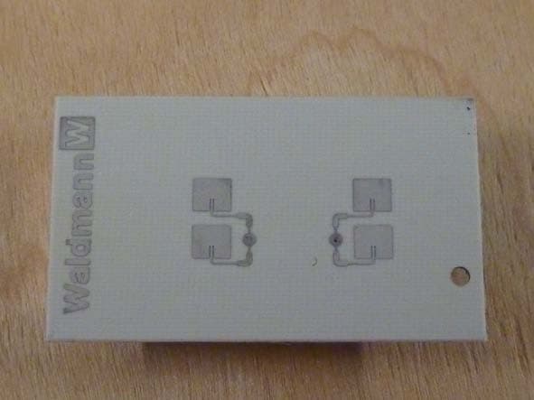
UXS-IPM224F
Oct 06, 2011Doppler Radar Module
Equipment Class
FDS - Part 15 Field Disturbance Sensor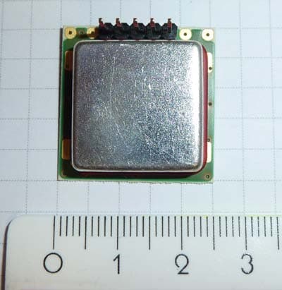
UXS2
Mar 22, 2011Doppler Radar Module
Equipment Class
FDS - Part 15 Field Disturbance Sensor