UXS-IVS97924 GHz Doppler Module
InnoSenT GmbH
Click to zoom
Application Details
- Equipment Class
- FDS - Part 15 Field Disturbance Sensor
- Date of Grant
- Jan 14, 2013
- Application Purpose
- Original Equipment
- Date of Application
- Jan 14, 2013
- Equipment Note
- 24 GHz Doppler Module
- Frequency Range
- 24123.00000000 - 24123.00000000
- Company
- InnoSenT GmbH
- Country
- Germany
Documents & Files
Document Text
Text extracted from the exhibit documents filed with the FCC. Open a document above to read the original.
Users Manual
InnoSenT sets standards – worldwide Page 1 Version 1.0 DATA SHEET IVS-979 Installa on Manual IVS-979 Version 1.0 - 15.03.2012 The IVS-979 is a K-Band VCO Transceiver with advanced SiGe MMIC technology that can be operated in FSK and FMCW mode. The sensor provides a special RF-design for maximum sensi! vity in long range appli- ca! ons such as traffi c monitoring or speed enforcement. Another smart new feature is the 1/x divider output for VCO tuning slope lineariza! on. InnoSenT GmbH has established and applies a quality system for: development, produc- ! on and sales of radar sensors for commer- cial and industrial sensors. An audit was performed, Report No. 010350 Proof has been furnished that the requirements according to DIN EN ISO 9001:2000 are fulfi lled. This product is compliant to the restric! on of hazardous substances (RoHS - European Union direc! ve 2002/95/EG) Features: »K-Band VCO Transceiver with advanced SiGe MMIC technology »FSK / FMCW modes »1/x divider for reference frequency output »stereo (dual channel) opera! on to detect direc! on of mo! on »integrated RF-pre-amplifi er Product Family Applica ons K-Band VCO Transceiver with advanced MMIC technology » Traffi c Monitoring Movement Velocity Direc! on Presence Distance Angle CONFIDENTIAL AND PROPRIETARY The informa! on contained in this document shall remain the sole and exclusive property of InnoSenT GmbH and shall not be disclosed by the recipient to third par! es without prior consent of InnoSenT in wri! ng. Descrip! on Cer! fi cates InnoSenT sets standards – worldwide Page 2 Version 1.0 DATA SHEET IVS-979 Oscillator transmit frequenciesf24.000 - 24.250GHzdepending on V tune varactor tuning voltageV tune 03V tuning bandwidth fi neDC500kHz tuning bandwidth coarseDC0.4Hz input impedance Vtune fi ne1k"200pf ESD protec# on input impedance Vtune coarse1k"200pf ESD protec# on tuning slope coarse340552766MHz/V tuning slope fi ne5996133MHz/V temperature dri$ frequency%f-4-5MHz/°C ouput power (EIRP)P ou-ETSI 20dBm@ room-temperature out of band radia# on (EIRP)P out of band -30dBm@ room-temperature divider ra# o factory se& ng1,280 for example 24.200GHz lead to 1.18MHz Receiver IF-amplifi ergain40dBpart number LT6204 bandwidth1002.5MHz output impedance100" signal levelS I/Q t.b.d.mV@ InnoSenT Test setup R I/Q t.b.d.mV@ InnoSenT Test setup IF-outputvoltage off set1.65V I/Q balanceamplitude6dB phase7095120° Antenna pa! ern (compare with antenna pa! ern on page 4) antenna pa* ern (@3dB)horizontal7°azimuth ver# cal28°eleva# on side lobe suppressionhorizontal15dBazimuth ver# cal15dBeleva# on Power Supply supply voltageV CC 5.35.56Vmax. 1mV PP ripple supply currentI CC 170mA Environment opera# ng temperatureT OP -30+60°C storage temperatureT STG -30+85°C outline dimensions120 x 72.5 x 10.65 (17.7)mmcompare drawing Electrical Characteris" cs ParameterSymbolMin.Typ.Max.UnitsComment CONFIDENTIAL AND PROPRIETARY The informa# on contained in this document shall remain the sole and exclusive property of InnoSenT GmbH and shall not be disclosed by the recipient to third par# es without prior consent of InnoSenT in wri# ng. Handling Precau" ons This InnoSenT sensor is sensi# ve to damage from ESD. Normal precau# ons as usally applied to CMOS devices are suffi cient when handling this device. Touching the signal output PINs has to be avoided at any # me before soldering or plugging the device into a motherboard. InnoSenT sets standards – worldwide Page 3 Version 1.0 DATA SHEET IVS-979 Tx - antenna pa ern 1MUXOUTOUT-digitalreference signal VCO frequency already divided by prescaler 2GNDground 3V CC IN-analog5.5V supply voltage 4SPI_CLOCKIN-digitalSPI-clock 5SPI_DATAIN-digitalSPI-data 6PLL_LEIN-digitallatch enable PLL 7d.n.c.do not connect 8CUST_PROG_LEIN-digitalenable customer programming (ac! ve low) 9d.n.c.IN-digitaldo not connect 10d.n.c.do not connect 11d.n.c.do not connect 12Q-SIGNALOUT-analogIF-output-signal 13I-SIGNALOUT-analogIF-output-signal 14V tune coarseIN-analogtuning voltage for coarse tuning VCO 15V tune fi neIN-analogtuning voltage for fi ne tuning VCO Pin #Descrip! onIn / OutComment CONFIDENTIAL AND PROPRIETARY The informa! on contained in this document shall remain the sole and exclusive property of InnoSenT GmbH and shall not be disclosed by the recipient to third par! es without prior consent of InnoSenT in wri! ng. Interface full beam width @ -3dBhorizontal7° ver! cal28° side-lobe suppression horizontal15dB vertical15dB ParameterSymbolMin.Typ.Max.UnitsComment output power [dBm] angle [°] The sensor provides a 2.54mm grid pin header. -40 -35 -30 -25 -20 -15 -10 -5 0 -180,0-150,0-120,0-90,0-60,0-30,00,030,060,090,0120,0150,0180,0 InnoSenT sets standards – worldwide Page 4 Version 1.0 DATA SHEET IVS-979 Mechanical Outlines All dimensions in mm Changes or modifi ca" ons made to the equipment not expressly approved by InnoSenT GmbH may void the FCC / IC authoriza" on to operate this equipment. The use of the transceiver module is authorized in mobile or fi xed host devices taking into account the condi" ons listed below: • OEM Integrator must ensure that the end user manual may not contain any informa" on about the way to install or remove the module from the fi nal product. • Depending on the fi nal host device addi" onal authoriza" on requirements for the non- transmi# er func" ons of the transmi# er module may be required (i.e., Verifi ca" on, or Declara" on of Conformity) The OEM integrator is responsible for ensuring that a$ er the module is installed and opera" onal the host con" nues to be compliant with the Part 15B uninten" onal radiator require- ments. • The informa" on on the label and in the user manual is required to be incorporated in the user manual of the fi nal host. see 47 CFR15 requirements for more details (e.g. 15.19 / 15.21 / 15.101 / 15.105 / RSS-GEN / ICES) • Addi" onal label with the words ‘Contains FCC ID:AAABBBBB’ and ‘Contains IC:AAAA-BBBB’ shall be applied and visible from the outside of the ho…
Text truncated - open the document above for the full version.
External Photos
- EXTERNAL PHOTOS - CONFIDENTIAL IVS-979 24GHz-Doppler-Module CONFIDENTIAL AND PROPRIETARY The information contained in this document is the exclusive property of InnoSenT GmbH and must not be disclosed by the recipient to third parties Seite 1 von 2 04.06.2012 InnoSenT GmbH Am Roedertor 30 97499 Donnersdorf GERMANY Tel.: 0049-9528-9518-0 Fax.: 0049-9528-9518-99 Documentation for FCC-approval - External Photos - Module : IVS-979 for InnoSenT GmbH Am Roedertor 30 97499 Donnersdorf GERMANY - EXTERNAL PHOTOS - CONFIDENTIAL IVS-979 24GHz-Doppler-Module CONFIDENTIAL AND PROPRIETARY The information contained in this document is the exclusive property of InnoSenT GmbH and must not be disclosed by the recipient to third parties Seite 2 von 2 04.06.2012 External Photos
ID Label/Location Info
- ID-LABEL / LOCATION INFO - CONFIDENTIAL IVS-979 24GHz-Doppler-Module CONFIDENTIAL AND PROPRIETARY The information contained in this document is the exclusive property of InnoSenT GmbH and must not be disclosed by the recipient to third parties Seite 1 von 2 04.06.2012 InnoSenT GmbH Am Roedertor 30 97499 Donnersdorf GERMANY Tel.: 0049-9528-9518-0 Fax.: 0049-9528-9518-99 Documentation for FCC-approval - ID-Label / Location Info - Module : IVS-979 for InnoSenT GmbH Am Roedertor 30 97499 Donnersdorf GERMANY - ID-LABEL / LOCATION INFO - CONFIDENTIAL IVS-979 24GHz-Doppler-Module CONFIDENTIAL AND PROPRIETARY The information contained in this document is the exclusive property of InnoSenT GmbH and must not be disclosed by the recipient to third parties Seite 2 von 2 04.06.2012 ID-Label/Location Info:
Internal Photos
- INTERNAL PHOTOS - CONFIDENTIAL IVS-979 24GHz-Doppler-Module CONFIDENTIAL AND PROPRIETARY The information contained in this document is the exclusive property of InnoSenT GmbH and must not be disclosed by the recipient to third parties Seite 1 von 2 11.06.2012 InnoSenT GmbH Am Roedertor 30 97499 Donnersdorf GERMANY Tel.: 0049-9528-9518-0 Fax.: 0049-9528-9518-99 Documentation for FCC-approval - Internal Photos - Module : IVS-979 for InnoSenT GmbH Am Roedertor 30 97499 Donnersdorf GERMANY - INTERNAL PHOTOS - CONFIDENTIAL IVS-979 24GHz-Doppler-Module CONFIDENTIAL AND PROPRIETARY The information contained in this document is the exclusive property of InnoSenT GmbH and must not be disclosed by the recipient to third parties Seite 2 von 2 11.06.2012 Internal Photos
Test Report
2012-06-28 Page 1 of 31 TEST REPORT Test report no.: 1-4521/12-01-03 Testing laboratory Applicant CETECOM ICT Services GmbH Untertuerkheimer Strasse 6 – 10 66117 Saarbruecken / Germany Phone: + 49 681 5 98 - 0 Fax: + 49 681 5 98 - 9075 Internet: http://www.cetecom.com e-mail: [email protected] Accredited Testing Laboratory: The testing laboratory (area of testing) is accredited according to DIN EN ISO/IEC 17025 (2005) by the Deutsche Akkreditierungsstelle GmbH (DAkkS) The accreditation is valid for the scope of testing procedures as stated in the accreditation certificate with the registration number: D-PL-12076-01-01 Area of Testing: Radio/Satellite Communications InnoSenT GmbH Am Rödertor 30 97499 Donnersdorf / GERMANY Phone: +49 9528 9518-0 Fax: Contact: Yvonne Lutz e-mail: [email protected] Phone: +49 9528 9518-85 Manufacturer InnoSenT GmbH Am Rödertor 30 97499 Donnersdorf / GERMANY Test standard/s 47 CFR Part 15 Title 47 of the Code of Federal Regulations; Chapter I Part 15 - Radio frequency devices RSS - 210 Issue 8 Spectrum Management and Telecommunications - Radio Standards Specification Low-power Licence-exempt Radiocommunication Devices (All Frequency Bands): Category I Equipment For further applied test standards please refer to section 3 of this test report. Test Item Kind of test item: K-Band VCO Transceiver Model name: IVS-979 FCC ID: UXS-IVS979 IC: -/- Frequency: 24.000 GHz – 24.250 GHz Antenna: Integrated patch antenna Power Supply: 5.5 V DC (V cc - supply voltage) 1.7 V DC (V tune coarse - VCO) Temperature Range: -30 °C to +60 °C This test report is electronically signed and valid without handwriting signature. For verification of the electronic signatures, the public keys can be requested at the testing laboratory. Test report authorised: Test performed: Karsten Geraldy Meheza Walla Senior Testing Manager Expert Test report no.: 1-4521/12-01-03 2012-06-28 Page 2 of 31 1 Table of contents 1 Table of contents............................................................................................................................................2 2 General information .......................................................................................................................................3 2.1 Notes and disclaimer ..........................................................................................................................3 2.2 Application details...............................................................................................................................3 3 Test standard/s ...............................................................................................................................................3 4 Test environment............................................................................................................................................4 5 Test item ..........................................................................................................................................................4 6 Test laboratories sub-contracted .................................................................................................................4 7 Summary of measurement results ...............................................................................................................5 8 RF measurement testing................................................................................................................................6 8.1 Description of test setup ....................................................................................................................6 8.1.1 Radiated measurements.............................................................................................................6 8.1.2 Additional comments ..................................................................................................................7 8.2 RSP100 test report cover sheet / performance test data ................................................................8 9 Measurement results......................................................................................................................................9 9.1 Field strength of emissions (wanted signal) ....................................................................................9 9.2 Occupied bandwidth (99% bandwidth) ...........................................................................................12 9.3 Field strength of emissions (radiated spurious) ............................................................................15 9.4 Conducted spurious emissions < 30 MHz ......................................................................................22 10 Test equipment and ancillaries used for tests ...................................................................................24 11 Observations .........................................................................................................................................25 Annex A Photographs of the test setup ......................................................................................................26 Annex B External photographs of the EUT.................................................................................................27 Annex C Internal photographs of the EUT ..................................................................................................28 Annex D Document history ..........................................................................................................................30 Annex E Further information........................................................................................................................30 Annex F Accreditation Certificate ...............................................................................................................31 Test report no.: 1-4521/12-01-03 2012-06-28 Page 3 of 31 2 General information 2.1 Notes and d…
Text truncated - open the document above for the full version.
Test Setup Photos
Test report no.: 1-4521/12-01-03 2012-06-28 Page 26 of 31 An ne x A P ho tog ra phs o f t h e te s t s e tu p Photo 1: Photo 2:
Contact Information
Applicant
Robert Mock
Test Firm
cetecom advanced GmbHGerald Schmidt
Technical Specifications
| # | Rule Parts | Frequency Range | Power Output |
|---|---|---|---|
| 1 | 15.245 | 24.12 GHz - 24.12 GHz | - |
Other Applications from InnoSenT GmbH
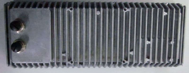
UXS-ITR-3800
May 29, 2023Stationary Traffic Monitoring
Equipment Class
DXX - Part 15 Low Power Communication Device Transmitter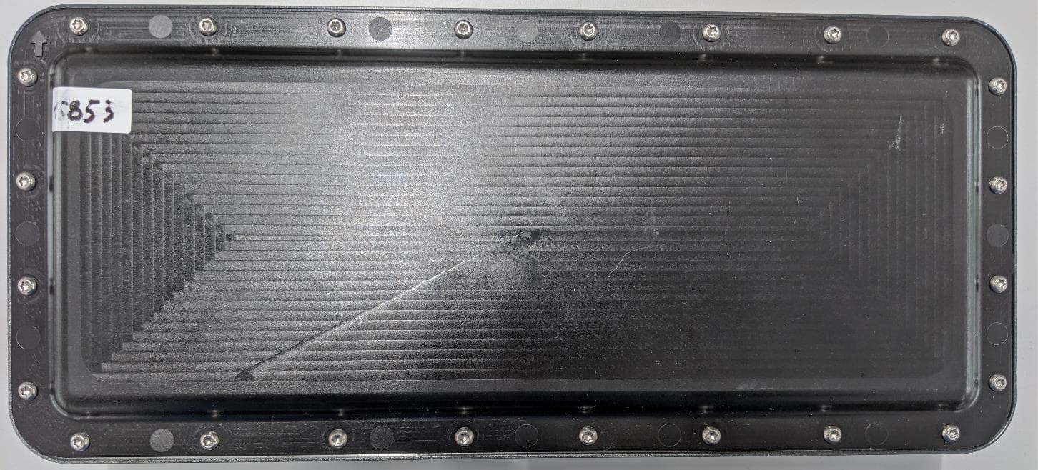
UXS-ISYS-5220
May 03, 2021K-Band Transceiver
Equipment Class
DXT - Part 15 Low Power Transceiver, Rx Verified
UXS-IPM165
Nov 14, 2013K-Band Transceiver
Equipment Class
FDS - Part 15 Field Disturbance Sensor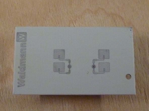
UXS-IPM224F
Oct 06, 2011Doppler Radar Module
Equipment Class
FDS - Part 15 Field Disturbance Sensor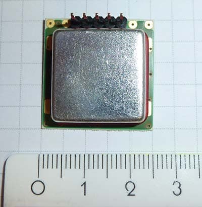
UXS2
Mar 22, 2011Doppler Radar Module
Equipment Class
FDS - Part 15 Field Disturbance Sensor