UXS-ITR-3800Stationary Traffic Monitoring
InnoSenT GmbH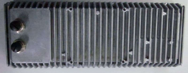
Click to zoom
Application Details
- Equipment Class
- DXX - Part 15 Low Power Communication Device Transmitter
- Date of Grant
- May 29, 2023
- Application Purpose
- Original Equipment
- Date of Application
- May 29, 2023
- Equipment Note
- Stationary Traffic Monitoring
- Frequency Range
- 24000.00000000 - 24250.00000000
- Company
- InnoSenT GmbH
- Country
- Germany
Documents & Files
Document Text
Text extracted from the exhibit documents filed with the FCC. Open a document above to read the original.
Users Manual
Rely on more Senses - www.innosent.de | 1 www.innosent.de—Leading in Radar User Manual Version 1.0 ITR-3800 www.innosent.de—Leading in Radar smart. comfortable. safe | 2 Experience and Reliability in Radar Technology 01. Safety Instructions 5 02. Sensor Description 6 2.1 Traffic Applications with the ITR-3800 7 2.1.1 Object List 7 2.1.2 Event Message 8 03. Mechanical Drawing 9 04. Accessories 10 06. Product Specification 12 07. Installation and Mounting 14 7.1 Mounting 14 7.2 Mounting Bracket 14 7.3 Installation 15 08. Connectors 16 8.1 Power Supply Connector 16 8.2 PoE | Ethernet Connector 16 09. Connection 17 9.1 External Power Supply | 24 - 48V DC 17 9.2 PoE | Power over Ethernet 18 10. Network Configuration 19 10.1 DHCP configuration with dynamic IP address 19 10.2 Static IP address 19 10.3 Network Hostname 20 10.4 UDP Settings 21 10.5 TCP / IP Settings 21 11. Communication 22 11.1 Read/Write Configuration 23 11.2 Object List 23 11.3 Event Messages 24 11.3.1 Zone Type Motion 24 11.3.2 Zone Type Presence 25 TABLE OF CONTENTS www.innosent.de—Leading in Radar smart. comfortable. safe | 3 Experience and Reliability in Radar Technology 12. Configuration using Traffic Manager 26 12.1 Installation of Traffic Manager 26 12.2 Overview of Traffic Manager 27 12.3 Connect to Camera Stream 27 12.4 Connect to ITR-3800 28 12.5 Configuration Wizard 28 12.5.1 Background 29 12.5.2 Reference Length 30 12.5.3 Sensor Position 31 12.5.4 Lineals 32 12.5.5 Event Zones 33 16.5.6 ETA - Estimated time of arrival 34 12.5.7 Ignore Zones 35 12.5.8 Text Label 36 12.6 Save Configuration 37 12.7 View Settings 38 12.8 Record / Playback 39 12.9 Firmware update 40 12.10 Restore Network Settings 40 12.11 Object List Traffic Manager 41 13. Traffic Application Implementations 42 13.1 Queue Length 43 13.2 Stop Bar Detection 44 13.3 Advance Detection 45 13.4 Wrong Way Detection 46 13.5 Traffic Counting 47 13.6 Pedestrian/Bike Counting with Sidewalk Zones 48 13.7 Working Example—An overview 49 13.8 Working Example—In 10 easy steps to our own configuration 50 13.9 Working Example—Application Stop Bar Detection 55 13.10 Working Example—Application Traffic Counting 56 13.11 Working Example—Application Queue Length 58 www.innosent.de—Leading in Radar smart. comfortable. safe | 4 Experience and Reliability in Radar Technology 14. Approvals 59 15. Disposal 59 16. Appendix 60 17. Contact 63 18. Known Issues 63 REFERENCE DOCUMENT [1] ITR-3800 User Manual - Mounting Bracket [2] ITR-3800 Quick Start Guide [3] ITR-3800_RadarAPI_readMe [5] ITR-3800 Data Sheet REVISION HISTORY VERSION DATE COMMENT 1.0 2022-12-02 Initial Release CO-APPLICABLE DOCUMENTS www.innosent.de—Leading in Radar smart. comfortable. safe | 5 Experience and Reliability in Radar Technology 1. SAFETY INSTRUCTIONS • Only skilled and instructed persons shall install and connect the devices. • Proper experience in working with mains voltage, electrical and electronic devices is required. • Do not connect the devices directly to mains voltage, instead use the voltage given in the manual • Do not wire any connections while power is applied to the device. • Ground the devices carefully to prevent electrical shock. • All connectors are pin-coded and fit in only one position. • Mount the devices carefully to prevent them from shifting or dropping. • The case must not be opened as this will void the warranty and cause incorrect calibration of the sensor. • The radome must not be painted, covered or glued over, as this will impair its function and cause incorrect calibration of the sensor. • Ensure adequate ventilation during operation. • The vent must not be covered. • All connected plugs must be screwed mechanically stable in order to comply with protection class IP67. • Unused connections should be covered with a sealing cap. • Use a shielding for the sensor if needed to protect against environmental conditions (snow, rain, dust) • Only use fully functional equipment (ladders, aerial work platform, ...) when working above ground. • Staff shall be capable of working at heights. • Use caution when installing the devices on or around active roadways. Pay attention to moving traffic. • The devices must be mounted to a stiff and solid support. • Vibration, oscillation or any kind of movement will reduce the sensor performance. • Make sure that your installation methods are in accordance with local safety policy and procedures and company practices. The protective conductor connection must not be used for other purposes. It must have a permanent electrical continuity and mechanical strength. Grounding connection: a: Screw b: Plain washer c: Cable lugs d: Contact washer www.innosent.de—Leading in Radar smart. comfortable. safe | 6 Experience and Reliability in Radar Technology 2. SENSOR DESCRIPTION The ITR-3800 is a 24GHz 4D/UHD radar sensor designed and developed for multiple-lane, multiple-target tracking, intersec- tion management and traffic monitoring applications. The newest member of InnoSenT’s radar fleet is designed for long-range and wide horizontal view to cover up to two slip roads to an intersection with multiple lanes. Measurements The sensor uses, with its Doppler based radial motion detection principle, innovative signal processing for optimal target detection. The measurements contain range, radial speed, azimuth and elevation angle, received signal strength and more parameters of the observed targets. This ensures a fast and efficient field of view coverage for excellent detection of moving targets, as well as stationary objects. Thanks to its high definition resolution the ITR-3800 is capable of separating up to 512 detections on up to 8 lanes, enabling many different traffic monitoring applications in scenarios with many objects present. Tracking After measuring the parameters of the detections, the ITR-3800 uses modern multiple-target tracking algorithms to generate an object list in every update cycle of 50ms. This object list, consisting of up to 128 tracks, pr…
Text truncated - open the document above for the full version.
Users Manual
Experience and Reliability in Radar Technology CONFIDENTIAL AND PROPRIETARY The information contained in this document shall remain the sole and exclusive property of InnoSenT GmbH and shall not be disclosed by the recipient to third parties without prior consent of InnoSenT in writing. Page 1 DATA SHEET ITR - 3800 InnoSenT Traffic Radar • Intersection Management • Traffic Monitoring • Arterial Management FEATURES: • 4D MIMO FMCW RADAR operating in the 24 GHz ISM band • Worldwide certification • Incorporates software enabled tracking and classification • Integrated Full HD camera • Lane separation up to 240m • Maximum detection range up to 300m • 4 classes detectable up to 183m • Velocity range from -233km/h to +233km/h DESCRIPTION The ITR-3800 Traffic Radar covers intersection management and traffic monitoring applications and provides the output of events. It has an integrated Full HD camera which enables the service technician to perform a much more efficient setup on the junction sites. Its modular design provides different interfaces, tailo- red to your needs. ADDITIONAL INFORMATION InnoSenT Standard Product. Changes will not be notified as long as there is no influence on form, fit or specified function of the product described within this data sheet. CERTIFICATES InnoSenT GmbH has established and implements a quali- ty system for: development, production and sales of radar sensors for industrial and automotive sensors. See more information on our quality standards at: https://www.innosent.de/en/company/certifications/ Movement Velocity Direction Presence Distance Angle Optics Experience and Reliability in Radar Technology CONFIDENTIAL AND PROPRIETARY The information contained in this document shall remain the sole and exclusive property of InnoSenT GmbH and shall not be disclosed by the recipient to third parties without prior consent of InnoSenT in writing. Page 2 DATA SHEET ITR - 3800 PARAMETER TYPICAL VALUE 1 UNIT Regulatory Operating Frequency 24.05 .. 24.25 GHz Bandwidth 200 MHz Output Power (EIRP) < 20dBm PK // < 108dBμV/m AVG Output Power (EIRP AVG) < 12.7 dBm Range Min. Detection Range 5 | 16.4 m | ft Max. Detection // Classification: Pedestrian 2 130 | 427 // 83 | 272 m | ft Max. Detection // Classification: Bike 2 130 | 427 // 83 | 272 m | ft Max. Detection // Classification: Car 2 300 | 984 // 183 | 600 m | ft Max. Detection // Classification: Truck 2 300 | 984 // 183 | 600 m | ft Range Accuracy 0.47 | 1.5 m | ft Lane Separation 9 : Approaching // Receding 220 | 722 // 240 | 787 m | ft Speed Radial Speed Resolution 0.46 | 0.29 km/h | mph Speed Range -233 .. +233 | -144.8 .. +144.8 km/h | mph Speed Accuracy 0.23 | 0.14 km/h | mph Angle Field of View: Azimuth 110 ° Field of View: Elevation 30 ° Separation: Azimuth 5 ° Angular Accuracy: Azimuth 0.5 ° Operational Mode 1: High Performance Mode 50 .. 75 ms Mode 2: Prediction Mode 56 ms Mode 3: Camera Mode 64 ms Processing Latency 1 cycle Initialization Time: DHCP // Static IP < 52 // < 49 s Interfaces Configuration A 8 PoE | Ethernet 1GBit/s | RS485 full duplex Configuration B External Power Supply | Ethernet 1GBit/s | RS485 full duplex Connectors M12 industrial PERFORMANCE 1 typical specifications are for general understanding and may vary 2 the classification parameter is defined as the max. distance up to which an object can be classified Experience and Reliability in Radar Technology CONFIDENTIAL AND PROPRIETARY The information contained in this document shall remain the sole and exclusive property of InnoSenT GmbH and shall not be disclosed by the recipient to third parties without prior consent of InnoSenT in writing. Page 3 DATA SHEET ITR - 3800 PARAMETER TYPICAL VALUE 1 UNIT Power supply Operating Voltage: DC 24 .. 48 | ±5% V Supply Current 3, 7 0.75 A Power Consumption: External Power Supply 3, 7 18 W Power Consumption: PoE 3, 7 20 W Camera Quality: Live Video Full HD (1920 x 1080p) Quality: Still Image Full HD (1920 x 1080p) Field of View: Diagonal 143 ° Field of View: Azimuth 121 ° Field of View: Elevation 73 ° Field of View: Range 5 .. 80 | 16.4 .. 262.5 m | ft Video Codec H.264 Frame Rate 30 Hz Environment Operating Temperature Radar -40 .. +80 °C Storage Temperature -40 .. +85 °C Operating Temperature Camera 4 -30 .. +70 °C Protection Class 5, 6 IP67 Mechanical Dimensions (with connectors): H/W/D 102 x 270 x 37 (47) | 4 x 10.6 x 1.5 (1.8) mm | in Weight < 1 | < 2.2 kg | lb Mounting VESA MIS-D 75 PERFORMANCE 3 the typical value is given for 24V at 19°C 4 the camera performance might be reduced by extreme temperatures 5 tested in independent laboratory 6 only IP67 protected, if cables and/or gaskets are plugged into connectors and screw-fastened with a torque of 0.4 Nm 7 current and power consumption increase with temperature and supply voltage 8 applied PoE standard: IEEE 802.3bt Type 3 „4PPoE“ 9 measured on highway with standard lane width of 3.75m Experience and Reliability in Radar Technology CONFIDENTIAL AND PROPRIETARY The information contained in this document shall remain the sole and exclusive property of InnoSenT GmbH and shall not be disclosed by the recipient to third parties without prior consent of InnoSenT in writing. Page 4 DATA SHEET ITR - 3800 MECHANICAL DRAWING Note: All dimensions in mm Experience and Reliability in Radar Technology CONFIDENTIAL AND PROPRIETARY The information contained in this document shall remain the sole and exclusive property of InnoSenT GmbH and shall not be disclosed by the recipient to third parties without prior consent of InnoSenT in writing. Page 5 DATA SHEET ITR - 3800 INTERFACES | Configuration A: PoE + Ethernet 1GBit/s + RS485 full duplex RS485 PoE INTERFACES | Configuration B: Ethernet + RS485 full duplex + power supply RS485 + power supply Ethernet INTERFACES The module provides two different interfacing possibilities. The user may choose which one to use. WARNING: Connect the module only as stated below. Do not interchange these options. Connections other than …
Text truncated - open the document above for the full version.
Users Manual
ITR-3800 Quick Start Guide 1.0 3. NETWORK CONFIGURATION 1. Start Traffic Manager SE. Click CONNECT button. more information on www.innosent.de—Leading in Radar smart. comfortable. safe. 2. SETUP NETWORK AND POWER SUPPLY Note - the system is preconfigured with DHCP - power up time is approximately 2 minutes - DHCP server must be available during power up 1. INSTALL TRAFFIC MANAGER SE The Traffic Manager SE‘s purpose is, to evaluate and configure the ITR-3800 traffic ra- dar. 1. Download the ITR-3800 Software Package at InnoSenT Download Portal 2. Please contact your InnoSenT contact person for the software activation key External Power Supply | 24 - 48V DC PoE | Power over Ethernet port 1 port 2 dhcp server PC / cabinet PoE injector port 2 port 1 power supply 24 - 48 V DC ethernet dhcp server PC / cabinet port 1 RS485 port 2 RS485 ethernet power PoE 2. When using more than one ITR-3800 in a network: - different devices can be determined by their unique hostname (printed on label) - hostname “ITR3800-XXXXXXXXXXXX” (X refers to MAC without hyphens) more information on www.innosent.de—Leading in Radar smart. comfortable. safe. 4. CONFIGURATION WITH INNOSENT TRAFFIC MANAGER SE For configuration follow the instructions of the configuration wizard (CONFIGURATION button) - send configuration to the ITR-3800 - save configuration on PC For a more detailed explanation of the Traffic Manager SE, please see ITR-3800 User Manual. 5. TYPICAL INSTALLATION OF THE ITR-3800 INSTALLATION PARAMETER MINIMUM TYPICAL 1 MAXIMUM UNIT Height 4 | 13 6 | 19 8 | 26 m | ft Elevation Angle -10 -7 0 ° Angle to Lane -60 6 60 ° Motion Zone 30 | 98 200 | 656 m | ft Presence Zone 20 | 65 80 | 262 m | ft 1 typical specifications are for general understanding and may vary ORIENTATION TOP side is tagged on the label on sensor backside. more information on www.innosent.de—Leading in Radar smart. comfortable. safe. SAFETY INSTRUCTIONS • Only skilled and instructed persons shall install and connect the devices. • Proper experience in working with mains voltage, electrical and electronic devices is required. • Do not connect the devices directly to mains voltage, instead use the voltage given in the manual. • Do not wire any connections while power is applied to the device. • Ground the devices carefully to prevent electrical shock. • All connectors are pin-coded and fit in only one position. • Mount the devices carefully to prevent them from shifting or dropping. • The case must not be opened as this will void the warranty and cause incorrect calibration of the sensor. • The radome must not be painted, covered or glued over, as this will impair its function and cause incorrect calibration. Grounding connection: a: screw b: plain washer c: cable lugs d: contact washer • Ensure adequate ventilation during operation. • The breather must not be covered. • All connected plugs must be screwed mechanically stable in order to comply with protection class IP67. • Unused connections should be covered with a sealing cap. • Use a shielding for the sensor if needed to protect against environmental conditions (snow, rain, dust). • Only use fully functional equipment (ladders, aerial work platform, ...) when working above ground. • Staff shall be capable of working at heights. • Use caution when installing the devices on or around active roadways. Pay attention to moving traffic. • The devices must be mounted to a stiff and solid support. • Vibration, oscillation or any kind of movement will reduce the sensor performance. • Make sure that your installation methods are in accordance with local safety policy and procedures and company practices. The protective conductor connection must not be used for other purposes. It must have a permanent electrical continuity and mechanical strength. more information on www.innosent.de—Leading in Radar smart. comfortable. safe. CONTACT INFORMATION InnoSenT GmbH Am Roedertor 30 97499 Donnersdorf GERMANY Phone: +49 9528 9518 0 E-Mail: [email protected] Web: www.innosent.de
Attestation Statements
V 8-5_7 Federal Communication Commission Authorization and Evaluation Division 7435 Oakland Mills Road Columbia, MD 21046 USA Donnersdorf den 13.04.2023 Attestation Statement according to 2.911(d)(5)(i) and 2.911(d)(5)(ii) FCC ID: UXS-ITR-3800 TO WHOM IT MAY CONCERN: Hereby we certify that the equipment for which authorization is sought is not “covered” equipment prohibited from receiving an equipment authorization pursuant to section 2.903 of the FCC rules. Further we certify that, as of the date of the filing of the application, InnoSenT GmbH is not identified on the Covered List as an entity producing “covered” equipment. Sincerely, Florian Fersch InnoSenT GmbH
Attestation Statements
V 8-5_7 Federal Communications Commission Authorization and Evaluation Division 7435 Oakland Mills Road Columbia, MD 21046 USA Date: 05/24/2023 Ref: Attestation Statement Part 2.911(d)(7) Filing Validity Period: 5 Years FCC ID: Unlimited InnoSenT GmbH Am Roedertor 30 97499 Donnersdorf GERMANY FCC FRN: 0015974322 certifies that, as of the dates of this application, Americas Compliance Consulting LLC dba iCertifi “iCertifi” is our designated U.S. agent for service of process for the above referenced FCC ID. We accept to maintain an agent for no less than one year after the grantee has terminated all marketing and importation or the conclusion of any commission-related proceeding involving the equipment. The US Agent for Service of Process is aware of and agrees to comply with the requirements outlined in the FCC Equipment Authorization Program, Report and Order FCC 22-84, and clause § 2.911. iCertifi accepts, as of the date of the filing of the application, the obligation of the designated U.S. agent for service process for the above: Designated U.S. Agent Information: Name Americas Compliance Consulting, LLC dba iCertifi FCC FRN 0033399411 Address 1001 SW Disk Drive, Suite 250 Bend, Oregon 97702 USA Contact Person Paul Preston Telephone (866) 885-4575 Email [email protected] Sincerely, InnoSenT GmbH Americas Compliance Consulting LLC dba iCertifi Florian Fersch Paul Preston
Cover Letter(s)
Document Version 1.1 2020-10-30 LONG-TERM CONFIDENTIALITY REQUEST for Certification Service in the USA Federal Communication Commission Equipment Authorization Division, Application Processing Branch 7435 Oakland Mills Road Columbia, MD 21048 TO WHOM IT M AY CONCERN Pursuant to Paragraphs §0.457 and 0.459 of the Commission’s Rules (47 C.F.R.) and Section §552(b)(4) of the Freedom of Information Act, we request Long-Term Confidentiality for the following product: For the product stated above, we request Long-Term Confidentiality for exhibits which contain Block Diagram, Operational Description, Parts List/Tune Up Info, Schematics, SDR Software/Security Info. The above exhibits contain ou r trade secrets and proprietary information that could be of benefit to o ur competitors. This information will not be publicly available. If you have any questions, please feel free to contact us at the address shown below. Sincerely, Company Name: Phone: Company Address: Fax: E-mail: Contact Name: Signature: Signature Date: Check your GC here. Click Grantee Search. FCC I D: Grantee Code Equipment Product Code
External Photos
Annex A No.1-5034/22-01-01_Annex_A External photos of the Device Under Test This document is electronically signed and valid without handwritten signature. For verification of the electronic signatures, the public keys can be requested at the testing laboratory. Document authorized: Meheza Walla Lab Manager Radio Communications CTC advanced GmbHUntertuerkheimer Str. 6-10 66117 Saarbruecken / Germany Phone: +49 681 5 98 - 0 Fax: +49 681 5 98 - 9075 web: ctcadvanced.com e-mail: [email protected] Photos Annex A Photo 1 Photo 2 - END OF DOCUMENT - 2023-01-20Document 1-5034/22-01-01_Annex_A2/2
ID Label/Location Info
- ID-LABEL / LOCATION INFO - ITR-3800, ITR-3800_ECO Stationary Traffic Monitoring CONFIDENTIAL AND PROPRIETARY The information contained in this document is the exclusive property of InnoSenT GmbH and must not be disclosed by the recipient to third parties Page 2 of 2 23.11.2020 ID-Label / Location Info
Internal Photos
Annex B No.1-5034/22-01-01_Annex_B Internal photos of the Device Under Test This document is electronically signed and valid without handwritten signature. For verification of the electronic signatures, the public keys can be requested at the testing laboratory. Document authorized: Meheza Walla Lab Manager Radio Communications CTC advanced GmbHUntertuerkheimer Str. 6-10 66117 Saarbruecken / Germany Phone: +49 681 5 98 - 0 Fax: +49 681 5 98 - 9075 web: ctcadvanced.com e-mail: [email protected] Photos Annex B Photo 1 Photo 2 2023-01-20Document 1-5034/22-01-01_Annex_B2/12 Photo 3 Photo 4 2023-01-20Document 1-5034/22-01-01_Annex_B3/12 Photo 5 Photo 6 2023-01-20Document 1-5034/22-01-01_Annex_B4/12 Photo 7 Photo 8 2023-01-20Document 1-5034/22-01-01_Annex_B5/12 Photo 9 Photo 10 2023-01-20Document 1-5034/22-01-01_Annex_B6/12 Photo 11 Photo 12 2023-01-20Document 1-5034/22-01-01_Annex_B7/12 Photo 13 Photo 14 2023-01-20Document 1-5034/22-01-01_Annex_B8/12 Photo 15 Photo 16 2023-01-20Document 1-5034/22-01-01_Annex_B9/12 Photo 17 Photo 18 2023-01-20Document 1-5034/22-01-01_Annex_B10/12 Photo 19 Photo 20 2023-01-20Document 1-5034/22-01-01_Annex_B11/12 Photo 21 - END OF DOCUMENT - 2023-01-20Document 1-5034/22-01-01_Annex_B12/12
RF Exposure Info
© CTC advanced GmbH Page 1 of 2 Maximum Permissible Exposure (MPE) & Exposure evaluation Report identification number: 1-5034/22-01-03 MPE (FCC) Certification numbers and labeling requirements FCC ID UXS-ITR-3800 This test report is electronically signed and valid without handwritten signature. For verification of the electronic signatures, the public keys can be requested at the testing laboratory. Document authorised: Alexander Hnatovskiy Marco Scigliano Lab Manager Testing Manager Radio Communications & EMC Radio Communications & EMC Report no.: 1-5034/22-01-03 © CTC advanced GmbH Page 2 of 2 EUT technologies: Technologies: Max. measured avg EIRP: [dBm] 24 GHz RadarTransceiver 8.5 NOTE: Max. measured value taken from CTC Advanced GmbH report 1-5034/22-01-02 (page23): 103.7 dBμV @3m = 8.5dBm Prediction of MPE limit at given distance - FCC Equation from page 18 of OET Bulletin 65, Edition 97-01 S = PG / 4 π R 2 where: S = Power density P = Power input to the antenna G = Antenna gain R = Distance to the center of radiation of the antenna PG = Output Power including antenna gain The table below is excerpted from Table 1B of 47 CFR 1.1310 titled “Limits for Maximum Permissible Exposure (MPE), Limits for General Population/Uncontrolled Exposure” Frequency Range (MHz) Power Density (mW/cm 2 ) Averaging Time (minutes) 300 -1500 f/1500 30 1500 - 100000 1.0 30 where f = Frequency (MHz) Prediction: worst case Technologies:RADAR Frequency (MHz)24000 PGDeclared max power (EIRP)8.5dBm RDistance20cm SMPE limit for uncontrolled exposure1 mW/cm 2 Calculated Power density: 0.0014mW/cm² Calculated percentage of Limit: 0.14% This prediction demonstrates the following: The power density levels for FCC at a distance of 20 cm are below the maximum levels allowed by regulations.
Test Report
BNetzA - CAB - 02/21 - 102 TEST REPORT Test report no.: 1-5034_22-01-02 Testing laboratory Applicant CTC advanced GmbH Untertuerkheimer Strasse 6 – 10 66117 Saarbruecken / Germany Phone: + 49 681 5 98 - 0 Fax: + 49 681 5 98 - 9075 Internet: https://www.ctcadvanced.com e-mail: [email protected] Accredited Testing Laboratory: The testing laboratory (area of testing) is accredited according to DIN EN ISO/IEC 17025 (2018-03) by the Deutsche Akkreditierungsstelle GmbH (DAkkS) The accreditation is valid for the scope of testing procedures as stated in the accreditation certificate starting with the registration number: D-PL-12076-01. InnoSenT GmbH Am Rödertor 30 97499 Donnersdorf / GERMANY Phone: +49 9528 9518-0 Contact: Cyrus Nabavinegad e-mail: [email protected] Manufacturer InnoSenT GmbH Am Rödertor 30 97499 Donnersdorf / GERMANY Test standard/s FCC - Title 47 CFR Part 15 FCC - Title 47 of the Code of Federal Regulations; Chapter I; Part 15 - Radio frequency devices For further applied test standards please refer to section 3 of this test report. Test Item Kind of test item: Stationary Traffic Monitoring Model name: ITR-3800 FCC ID: UXS-ITR-3800 Frequency: 24.00 GHz – 24.25 GHz Antenna: Integrated patch antenna Power supply: 24 V – 48 V DC (0.76 A) Temperature range: -40°C to +80°C This test report is electronically signed and valid without handwritten signature. For verification of the electronic signatures, the public keys can be requested at the testing laboratory. Test report authorized: Test performed: Thomas Vogler Meheza Walla Lab Manager Lab Manager Radio Communications & EMC Radio Communications & EMC Test report no.: 1-5034_22-01-02 © CTC advanced GmbH Page 2 of 54 1 Table of contents 1 Table of contents ....................................................................................................................................... 2 2 General information ................................................................................................................................... 3 2.1 Notes and disclaimer ...................................................................................................................... 3 2.2 Application details .......................................................................................................................... 3 2.3 Test laboratories sub-contracted .................................................................................................... 3 3 Test standard/s, references and accreditations ......................................................................................... 4 4 Reporting statements of conformity – decision rule .................................................................................. 5 5 Test environment ....................................................................................................................................... 6 6 Test item ................................................................................................................................................... 6 6.1 General description ......................................................................................................................... 6 6.2 Additional information .................................................................................................................... 6 7 Description of the test setup ...................................................................................................................... 7 7.1 Shielded semi anechoic chamber .................................................................................................... 8 7.1 Shielded fully anechoic chamber ................................................................................................... 10 7.2 Radiated measurements > 18 GHz ................................................................................................ 12 7.3 Radiated measurements > 50/85 GHz ........................................................................................... 12 7.4 AC power-line conducted emissions ............................................................................................. 14 8 Sequence of testing ................................................................................................................................. 15 8.1 Sequence of testing radiated spurious 9 kHz to 30 MHz ............................................................... 15 8.2 Sequence of testing radiated spurious 30 MHz to 1 GHz ............................................................... 16 8.3 Sequence of testing radiated spurious 1 GHz to 18 GHz................................................................ 17 8.4 Sequence of testing radiated spurious above 18 GHz .................................................................... 18 8.5 Sequence of testing radiated spurious above 50/85 GHz with external mixers .............................. 19 9 Measurement uncertainty ........................................................................................................................ 20 10 Far field consideration for measurements above 18 GHz .................................................................. 20 11 Summary of measurement results .................................................................................................... 21 12 Measurement results ........................................................................................................................ 22 12.1 Field strength of fundamental emission ..................................................................................... 22 12.2 Occupied bandwidth (99% bandwidth) ....................................................................................... 25 12.3 Field strength of emissions (radiated spurious) ......................................................................... 26 12.4 Conducted emissions < 30 MHz ..............................…
Text truncated - open the document above for the full version.
Test Setup Photos
Annex D No.1-5034/22-01-01_Annex_D Setup photos of the Device Under Test This document is electronically signed and valid without handwritten signature. For verification of the electronic signatures, the public keys can be requested at the testing laboratory. Document authorized: cn=Meheza Walla, o=CTC advanced GmbH, ou=WAL-200806, email=meheza.walla@ctcadvance d.com, c=DE 2023.01.20 15:12:11 +01'00' Meheza Walla Lab Manager Radio Communications CTC advanced GmbH Untertuerkheimer Str. 6-10 66117 Saarbruecken / Germany Phone: +49 681 5 98 - 0 Fax: +49 681 5 98 - 9075 web: ctcadvanced.com e-mail: [email protected] 2023-01-20 Document 1-5034/22-01-01_Annex_D 2/4 Photos Annex D Photo 2 Photo 1 2023-01-20 Document 1-5034/22-01-01_Annex_D 3/4 Photo 4 Photo 3 2023-01-20 Document 1-5034/22-01-01_Annex_D 4/4 Photo 6 Photo 5 2023-01-20 Document 1-5034/22-01-01_Anne…
Text truncated - open the document above for the full version.
Contact Information
Applicant
Robert Mock
Test Firm
cetecom advanced GmbHGerald Schmidt
Technical Specifications
| # | Rule Parts | Frequency Range | Power Output |
|---|---|---|---|
| 1 | 15C | 24.00 GHz - 24.25 GHz | - |
Other Applications from InnoSenT GmbH
UXS-ISYS-5220
May 03, 2021K-Band Transceiver
Equipment Class
DXT - Part 15 Low Power Transceiver, Rx Verified
UXS-IPM165
Nov 14, 2013K-Band Transceiver
Equipment Class
FDS - Part 15 Field Disturbance Sensor
UXS-IVS979
Jan 14, 201324 GHz Doppler Module
Equipment Class
FDS - Part 15 Field Disturbance Sensor
UXS-IPM224F
Oct 06, 2011Doppler Radar Module
Equipment Class
FDS - Part 15 Field Disturbance Sensor
UXS2
Mar 22, 2011Doppler Radar Module
Equipment Class
FDS - Part 15 Field Disturbance Sensor