UY6-RFM96DFM Receiver
TOHNICHI MFG. CO., LTD
Click to zoom
Application Details
- Equipment Class
- CYY - Communications Receiver used w/Pt 15 Transmitter
- Date of Grant
- Feb 25, 2007
- Application Purpose
- Original Equipment
- Date of Application
- Feb 25, 2007
- Equipment Note
- FM Receiver
- Frequency Range
- 41.02500000 - 41.30000000
- Company
- TOHNICHI MFG. CO., LTD
- Country
- Japan
Documents & Files
Document Text
Text extracted from the exhibit documents filed with the FCC. Open a document above to read the original.
Users Manual
FM REMOTE SIGNAL TORQUE WRENCH FM96MCU OPERATION MANUAL 1 Precaution 1. Place the Unit apart form the metallic structure. 2. Do not place the receiver and the transmitter where the antenna contacts with metal or electric wire. 3. Do not cut or curl the antenna or the receiver. 4. Do not use the Unit where the electromagnetic noise takes place by welding machines, electrical discharge machines, PC, etc. 5. If there are any questions, place contact Tohnichi sales office or Tohnichi authorized distributor. FCC Regulatory Compliance Statement This equipment has been tested and found to comply with the limits for a Class B digital device, pursuant to Part 15 of the FCC rules. These limits are designed to provide reasonable protection against harmful interference in a residential installation. This equipment generates, uses, and can radiate radio frequency energy and, if not installed and used in accordance with the instructions, may cause harmful interference to radio communications. However, there is no guarantee that interference will not occur in a particular installation. If this equipment does cause harmful interference to radio or television reception, which can be determined by turning the equipment off and on, the user is encouraged to try to correct the interference by one or more of the following measures: • Reorient or relocate the receiving antenna. • Increase the separation between the equipment and receiver. • Connect the equipment into an outlet on a circuit different from that to which the receiver is connected. • Consult the dealer or an experienced radio/TV technician for help. This device complies with Part 15 of the FCC Rules. Operation is subject to the following two conditions: (1) This device may not cause harmful interference, and (2) This device must accept any interference received, including interference that may cause undesired operation. Caution: Any changes or modifications not expressly approved by the party responsible for product compliance could void the user's authority to operate the equipment. Canada Regulatory Compliance Statement This Class B digital apparatus complies with Canadian ICES-003. Cet appareil numériqué de la classe B est conformé à la norme NMB-003 du Canada. For Customers in Canada This device complies with RSS 210 of Industry Canada (IC). Operation is subject to the following two conditions: (1) this device may not cause interference, and (2) this device must accept any interference, including interference that may cause undesired operation of this device. L’ utilisation de ce dispositif est autorisée seulement aux conditions suivantes : (1) il ne doit pas produire de brouillage et (2) l’ utilisateur du dispositif doit étre prêt à accepter tout brouillage radioélectrique reçu, même si ce brouillage est susceptible de compromettre le fonctionnement du dispositif.. 2 <INDEX> . Outline................................................................................................ 3 . Features.............................................................................................. 3 . Construction...................................................................................... 3 . Specifications..................................................................................... 4 . Transmitter-appearance and components.................................. 5 . Receiver-appearance and components......................................... 6 . Precaution.......................................................................................... 7 - Power supply.............................................................................. 7 - Placing the receiver................................................................... 7 - Connection with other apparatus.......................................... 7 . Operation........................................................................................... 8 - Precaution................................................................................... 8 - Replacing battery for transmitter.......................................... 8 - Setting the Time to avoid Double Counting.................................. 8 - Battery Check............................................................................. 9 - Changing channel...................................................................... 9 . Connection to CNA-4mk2......................................................... 10 . Applicable Frequency.................................................................... 11 . Setting the Channel of the Transmitter.................................... 12 . Setting the Channel of the Receiver.......................................... 13 . Receiver Board................................................................................ 14 . FM Board Replacement Procedure..................................................... 15 . Optional Unit.................................................................................. 17 . Troubleshooting.............................................................................. 18 3 1. Outline The FM Remote Signal Torque Wrench integrates a wireless signal generator that counts down the number of bolts or nuts after tightened. The signal transmitter can be installed onto TOHNICHI torque wrenches, such as Models QSP, CSP, PQL, PCL, SP, RSP, etc. It is easy to set the required channel on customer side. 96 channels are available for the Receiver and 16 channels for the Transmitter. The receiver can be connected to the CNA-4mk2 Count Checker to provide complete tightening assurance system to eliminate missed tightening. 2. Features This Remote Signal Type torque wrench sends the tightening completion signal to the Receiver far from the wrench through FM-wave. Tone frequency of FM-wave can be easily set. This feature reduces the number of the Remote Signal torque wrenches for spare and a few torque wrenches enable the more tightening control applications. 3. Construct…
Text truncated - open the document above for the full version.
Cover Letter(s)
Set-up Procedure for R-FM96D 1. The receive antenna consists of 2 parts. By using tool like Figure 1, assemble 2 parts. Then, install the antenna on R-FM96D Receiver like Figure 2. Figure 1 Figure 2 2. Put Power ON. Then, “Power” LED lights up and the receiver starts continuous receiving. 3. When it receives from the transmitter, “Signal” LED lights up. Note that “Signal” LED turns off in a second because it is controlled by timer, but the Receiver receives even if “Signal” LED turns off. There is no separate receive mode and no standby mode.
ID Label/Location Info
PROPOSED ID LABEL LOCATION Tohnichi Mfg.Co.,Ltd Model #:R-FM96D IC:6561B-RFM96D FCC ID:UY6-RFM96D
Test Report
FCC CFR47 PART 15 SUBPART B TEST REPORT FOR FM RECEIVER FCC ID: UY6-RFM96D MODEL NUMBER: R-FM96D REPORT NUMBER: 07J10799-1 ISSUE DATE: FEBRUARY 09, 2007 Prepared for TOHNICHI MFG. CO., LTD 2-12 OMORI-KITA 2-CHOME, OTA-KU TOKYO 143-0016, JAPAN Prepared by COMPLIANCE CERTIFICATION SERVICES 47173 BENICIA STREET FREMONT, CA 94538, U.S.A. TEL: (510) 771-1000 FAX: (510) 661-0888 REPORT NO: 06J10799-1 DATE: FEBRUARY 09, 2007 EUT: FM RECEIVER FCC ID: UY6-RFM96D Page 2 of 20 COMPLIANCE CERTIFICATION SERVICES DOCUMENT NO: CCSUP4031A 47173 BENICIA STREET, FREMONT, CA 94538, USA TEL: (510) 771-1000 FAX: (510) 661-0888 This report shall not be reproduced except in full, without the written approval of CCS. Revision History Rev. Issue Date Revisions Revised By -- 02/09/07 Initial Issue T. C. REPORT NO: 06J10799-1 DATE: FEBRUARY 09, 2007 EUT: FM RECEIVER FCC ID: UY6-RFM96D Page 3 of 20 COMPLIANCE CERTIFICATION SERVICES DOCUMENT NO: CCSUP4031A 47173 BENICIA STREET, FREMONT, CA 94538, USA TEL: (510) 771-1000 FAX: (510) 661-0888 This report shall not be reproduced except in full, without the written approval of CCS. TABLE OF CONTENTS 1. ATTESTATION OF TEST RESULTS............................................................................................. 4 2. TEST METHODOLOGY .................................................................................................................. 5 3. FACILITIES AND ACCREDITATION .......................................................................................... 5 4. CALIBRATION AND UNCERTAINTY.......................................................................................... 5 4.1. MEASURING INSTRUMENT CALIBRATION ............................................................................. 5 4.2. MEASUREMENT UNCERTAINTY ............................................................................................... 5 5. EQUIPMENT UNDER TEST............................................................................................................6 5.1. DESCRIPTION OF EUT ..............................................................................................................6 5.2. PRELIMINARY TEST CONFIGURATIONS................................................................................. 7 5.3. MODE(S) OF OPERATION ......................................................................................................... 7 5.4. MODIFICATIONS ........................................................................................................................ 7 5.5. DETAILS OF TESTED SYSTEM .................................................................................................. 8 6. TEST AND MEASUREMENT EQUIPMENT ................................................................................ 9 7. APPLICABLE LIMITS AND TEST RESULTS ........................................................................... 10 7.1. RADIATED EMISSIONS.............................................................................................................10 7.2. AC MAINS LINE CONDUCTED EMISSIONS ........................................................................... 13 8. SETUP PHOTOS .............................................................................................................................. 17 REPORT NO: 06J10799-1 DATE: FEBRUARY 09, 2007 EUT: FM RECEIVER FCC ID: UY6-RFM96D Page 4 of 20 COMPLIANCE CERTIFICATION SERVICES DOCUMENT NO: CCSUP4031A 47173 BENICIA STREET, FREMONT, CA 94538, USA TEL: (510) 771-1000 FAX: (510) 661-0888 This report shall not be reproduced except in full, without the written approval of CCS. 1. ATTESTATION OF TEST RESULTS COMPANY NAME: TOHNICHI MFG. CO., LTD 2-12, OMORI-KITA 2-CHOME OTA-KU, TOKYO, 143-0016, JAPAN EUT DESCRIPTION: FM RECEIVER MODEL: R-FM96D SERIAL NUMBER: 801180V DATE TESTED: JANUARY 25, 2007 APPLICABLE STANDARDS STANDARD TEST RESULTS FCC PART 15 SUBPART B NO NON-COMPLIANCE NOTED Compliance Certification Services, Inc. tested the above equipment in accordance with the requirements set forth in the above standards. The test results show that the equipment tested is capable of demonstrating compliance with the requirements as documented in this report. Note: The results documented in this report apply only to the tested sample, under the conditions and modes of operation as described herein. This document may not be altered or revised in any way unless done so by Compliance Certification Services and all revisions are duly noted in the revisions section. Any alteration of this document not carried out by Compliance Certification Services will constitute fraud and shall nullify the document. No part of this report may be used to claim product certification, approval, or endorsement by NVLAP, NIST, or any government agency. Approved & Released For CCS By: Tested By: THU CHAN MENGISTU MEKURIA EMC SUPERVISOR EMC ENGINEER COMPLIANCE CERTIFICATION SERVICES COMPLIANCE CERTIFICATION SERVICES REPORT NO: 06J10799-1 DATE: FEBRUARY 09, 2007 EUT: FM RECEIVER FCC ID: UY6-RFM96D Page 5 of 20 COMPLIANCE CERTIFICATION SERVICES DOCUMENT NO: CCSUP4031A 47173 BENICIA STREET, FREMONT, CA 94538, USA TEL: (510) 771-1000 FAX: (510) 661-0888 This report shall not be reproduced except in full, without the written approval of CCS. 2. TEST METHODOLOGY The tests documented in this report were performed in accordance with ANSI C63.4-2003. 3. FACILITIES AND ACCREDITATION The test sites and measurement facilities used to collect data are located at 47173 Benicia Street, Fremont, California, USA. The sites are constructed in conformance with the requirements of ANSI C63.4, ANSI C63.7 and CISPR Publication 22. All receiving equipment conforms to CISPR Publication 16-1, “Radio Interference Measuring Apparatus and Measurement Methods.” CCS is accredited by NVLAP, Laboratory Code 200065-0. The full scope of accreditation can be viewed at http://www.ccsemc.com . 4. CALIBRATION AND UNCERTAINTY 4.1. MEASURING INSTRUMENT CALIB…
Text truncated - open the document above for the full version.
Test Setup Photos
REPORT NO: 06J10799-1 DATE: FEBRUARY 09, 2007 EUT: FM RECEIVER FCC ID: UY6-RFM96D Page 17 of 20 COMPLIANCE CERTIFICATION SERVICES DOCUMENT NO: CCSUP4031A 47173 BENICIA STREET, FREMONT, CA 94538, USA TEL: (510) 771-1000 FAX: (510) 661-0888 This report shall not be reproduced except in full, without the written approval of CCS. 8. SETUP PHOTOS RADIATED EMISSION RADIATED EMISSIONS (FRONT) REPORT NO: 06J10799-1 DATE: FEBRUARY 09, 2007 EUT: FM RECEIVER FCC ID: UY6-RFM96D Page 18 of 20 COMPLIANCE CERTIFICATION SERVICES DOCUMENT NO: CCSUP4031A 47173 BENICIA STREET, FREMONT, CA 94538, USA TEL: (510) 771-1000 FAX: (510) 661-0888 This report shall not be reproduced except in full, without the written approval of CCS. RADIATED EMISSIONS (BACK) REPORT NO: 06J10799-1 DATE: FEBRUARY 09, 2007 EUT: FM RECEIVER FCC ID: UY6-RFM96D Page 19 of 20 COMPLIANCE CERTIFICATION SERVICES DOCUMENT NO: CCSUP4031A 47173 BENICIA STREET, FREMONT, CA 94538, USA TEL: (510) 771-1000 FAX: (510) 661-0888 This report shall not be reproduced except in full, without the written approval of CCS. AC MAINS LINE CONDUCTED EMISSION LINE CONDUCTED EMISSION (FRONT) REPORT NO: 06J10799-1 DATE: FEBRUARY 09, 2007 EUT: FM RECEIVER FCC ID: UY6-RFM96D Page 20 of 20 COMPLIANCE CERTIFICATION SERVICES DOCUMENT NO: CCSUP4031A 47173 BENICIA STREET, FREMONT, CA 94538, USA TEL: (510) 771-1000 FAX: (510) 661-0888 This report shall not be reproduced except in full, without the written approval of CCS. END OF REPORT LINE CONDUCTED EMISSION (BACK)
Contact Information
Applicant
Satoshi Takaku
Test Firm
Compliance Certification ServicesBarbara Judge
Technical Specifications
| # | Rule Parts | Frequency Range | Power Output |
|---|---|---|---|
| 1 | 15B | 41.025 MHz - 41.3 MHz | - |
Other Applications from TOHNICHI MFG. CO., LTD
UY6-FHLSM
Mar 01, 2021Module with communication function for sending and receiving data to and from compatible wireless devices
Equipment Class
DSS - Part 15 Spread Spectrum Transmitter
UY6-TFHSLS
Aug 11, 2013Remote Control Transmitter Module
Equipment Class
DXX - Part 15 Low Power Communication Device Transmitter
UY6-FMAM
May 05, 2013RF module
Equipment Class
DXT - Part 15 Low Power Transceiver, Rx Verified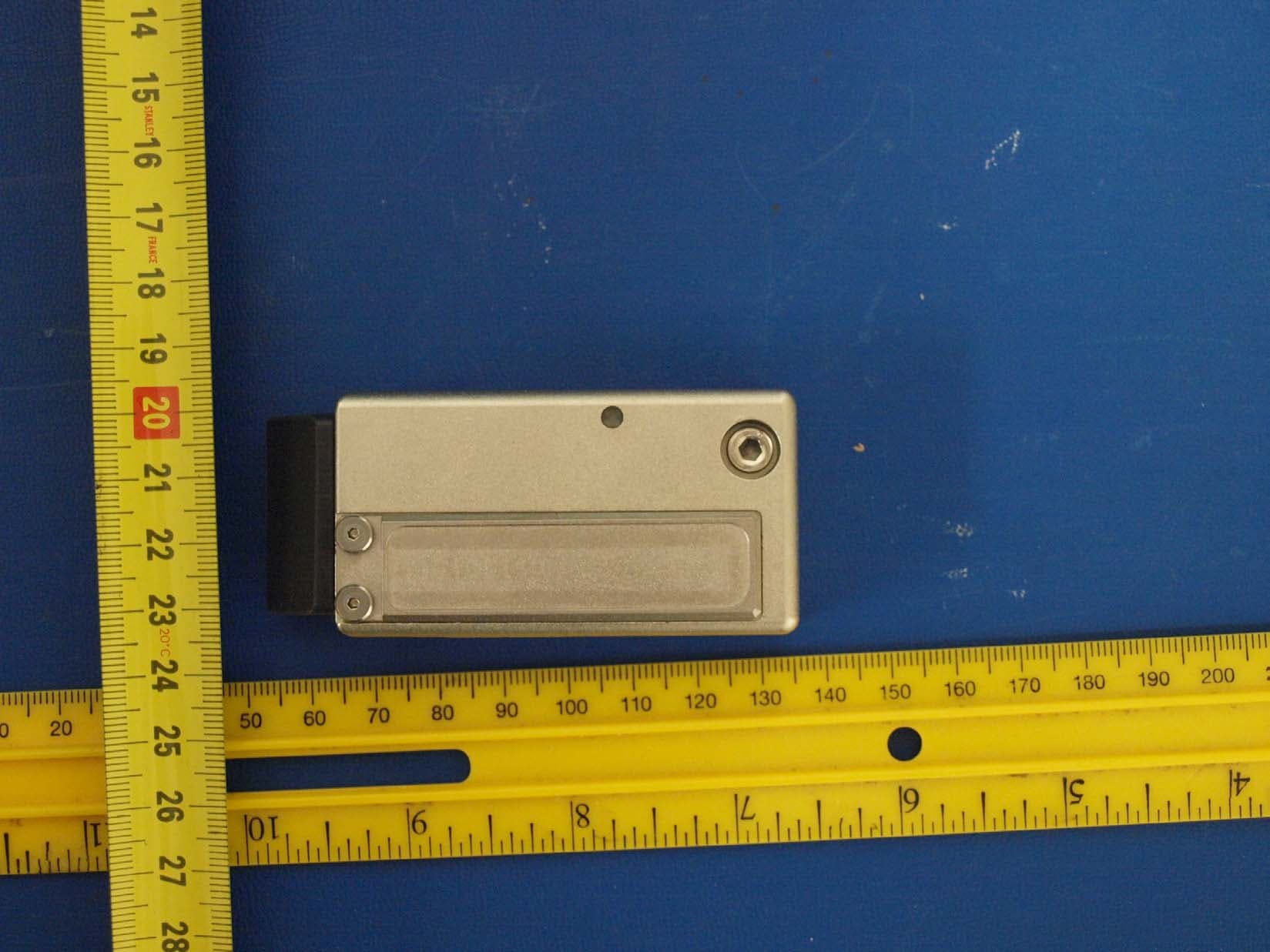
UY6-TFH256MCAR
Jan 31, 2011RF TRANSCEIVER
Equipment Class
DXT - Part 15 Low Power Transceiver, Rx VerifiedUY6-FHD256M
May 16, 2008RF Module
Equipment Class
DXT - Part 15 Low Power Transceiver, Rx Verified