VHH-GM2400WIRELESS A/V TRANSMITTER AND RECEIVER
QINGYUAN GADMEI ELECTRONICS TECHNOLOGY Co., Ltd.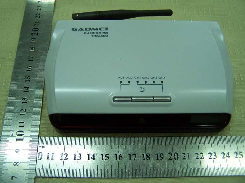
Click to zoom
Application Details
- Equipment Class
- DXX - Part 15 Low Power Communication Device Transmitter
- Date of Grant
- Jul 26, 2007
- Application Purpose
- Original Equipment
- Date of Application
- Jul 26, 2007
- Equipment Note
- WIRELESS A/V TRANSMITTER AND RECEIVER
- Frequency Range
- 2414.00000000 - 2468.00000000
- Country
- China
Documents & Files
Document Text
Text extracted from the exhibit documents filed with the FCC. Open a document above to read the original.
Users Manual
GM2400 WIRELESS A/V TRANSCEIVER User's Manual If you have any questions related to this product, please E-mail to our company to : [email protected], or visit our company's website at www.gadmei.com GADMEI-GM2400 User's Manual-V1.0 Introduction 1.1 Function and Features 1.2 Application 1.3 Accessories 1.4 Technical specifications Hardware and Installation 2.1 Transmitter (TXV2400) Buttons and Rear Panel Instructions 2.2 Receiver (TRV2400) Buttons and Rear Panel Instructions 2.3 Placement of Transmitter (TXV2400) 2.4 Placement of Receiver (TRV2400) 2.5 Placement of Antenna Operation Instruction 3.1 Signal Channel Selection 3.2 Power Switch 3.3 Channel Selection 3.4 Infrared control feedback FAQ and Troubleshooting --------------------------------------------------1 -----------------------------------1 -----------------------------------------------1 -----------------------------------------------2 ---------------------------------2 -----------------------------------3 --------------------3 --------------------3 -------------------4 ----------------------6 -----------------------------------6 ----------------------------------------7 --------------------------------7 ---------------------------------------------7 ----------------------------------------8 -------------------------------9 ---------------------------------10 CONTENTS 1. 2. 3. 4. 4. FAQ and Troubleshooting Indicator does not light and there is no image Make sure there is power supply of the transceiver. Change receiver's transmitting channel (refer to operation instruction/ Channel switch). Adjust transceiver's placement (refer to hardware and installation instruction). Infrared Control Feedback malfunction Make sure that the connection and installation of the transmitter is correct.(refer to hardware and installation instruction). Please adjust transceiver's antenna and placement (refer to placement of antenna). image is interfered Change receiver's transmitting channel (refer to Channel selection). Please adjust transceiver's placement (refer to hardware and installation instruction) 1. 2. 3. 1. 2. 1. 2. Thanks for use GADMEI GM2400 wireless A/V transceiver! In order to use our product more conveniently, please read this manual carefully. 3.4 Infrared Remote Feedback GM2400 wireless AV transceiver doesn't need specified remote, but it has infrared remote feedback function. When emitting source came from set-top box (STB), DVD, video camera with remote function, remoter come with these equipments can be used directly on the receiver (TRV2400), while you don't have to operate the remote control of the AV equipments. Step one: Refer to connecting installation picture, connect transmitter (TXV2400), and confirm there are no barriers between transmitter's infrared window and infrared receiving window of program source. Step two: When enjoying programs from receiver (TRV2400), point remoter to remote receiving window of the receiver, then you can control AV equipments, which is easy and convenient for operation. Tips: Please pull 433 Mhz antenna of transmitter and receiver as straight as possible, and keep it far away from AV cables,to ensure no interference to signal transmission. In case of infrared remote malfunction, please check antenna's placement on condition that there is no placement problem with the transceiver. 1. Introduction 1.1 Function and Features GM2400 wireless A/V transceiver consists of Transmitter (TXV2400) and receiver (TRV2400). It adopts advanced 2.4GHz wireless transmission technology, with strong anti-interference and mobility. When used in conjunction with set-top box, DVD, VCD and etc, it can be installed easily, subject to no space limitation and without any use of wire connection. It can make audio and video transmitting easily available in every room at home, letting you enjoy HIFI audio and video freely at every corner at home. There are 4 channels, and the frequency scope ranges from 2.400GHz to 2.483GHz; In order to increase the flexibility and reliability, we prepare four selectable channels (2.414GHZ, 2.432GHz, 2.450GHz, 2.468GHz); 2.4 GHz wireless transmitter and receiver with 4 selectable channels (Tact Switch) Compatible with AV output equipments such as video recorder, video camera, digital camera and digital set-top box 433MHz infrared remote returning transmission, fully compatible with remote control of DVD/VCD/ digital et-top box Strong infrared emission, no need to install infrared emission extension cord Received image is clear and stable, with bright color, and stereo sound Support NTSC/PAL system video and stereophonic audio transmis- sion Complete hardware design, no need to install software, plug and play, easy and convenient TRV2400 Four transmission channels of 2.4GHz can be switched freely by pressing channel switch button. But only when the transceiver is in the same channel can video signals be transmitted normally. Panel indicator light for each channel selection mode goes as below: Please select Channel one or four, to avoid signal interference by wireless local area network (LAN),when there is LAN(802.11 or WiFi) in your family. 3.3 Channel Selection The first channel selection mode The third channel selection mode The second channel selection mode The fourth channel selection mode TXV2400 Tips: 1.2 Application A/V to A/V wireless transmission, can be used when many televi- sions share one DVD/VCD or one digital set-top box and etc. Video conference system in large conference room, and multimedia teaching in classroom. Connect to pick-up head for monitoring;can be used in security systems. Building and industry monitoring system, long-distance custody of children and patient . Places where construction is difficult or cost is high. 1.3 Accessories Transmitter (TXV2400)--------------------------------------------1pcs Receiver (TRV2400) --------------------------------------------1pcs Power adapter---------------------------------------------------2pcs AV cable---------------…
Text truncated - open the document above for the full version.
Block Diagram
Av 2 4053 DC 5V AV 2.4G CHANNEL IR OUT 433MHz RECEIVER 2.4G TRANSMITTER EM78P447 5V 5V 24C04 KEY LED AV OUT DC 5V 2.4G CHANNEL IR IN 433MHz TRANSMITTER 2.4G RECEIVER EM78P447 5V 5V KEY LED AV 24C04 I2C I2C AV 1 / AV 2 TXV2400 TRV2400
Cover Letter(s)
Declaration of Authorization We Name: GADMEI ELECTRONICS TECHNOLOGY CO., LTD. Address: Yin Zhan Farm, Qing Cheng District, Qing Yuan City, Guangdong Province City: Qing Yuan Country: China Declare that: Name: SHENZHEN EMTEK Co., Ltd. ............ . Address: Bldg 69, Majialong Industry Zone, Nanshan District, Shenzhen, Guangdong China. City: Shenzhen Country China is authorized to apply for Certification of the following product(s): Product description: Wireless A/V Transmitter & Receiver Type designation: GM2400 Trademark: GADMEI on our behalf. Date: July 05, 2007 City: Qing Yuan Name: Zhang Hongzhong Signature: Zhang Hongzhong
External Photos
EXTERNAL PHOTO
ID Label/Location Info
FCC ID LABEL Location This device complies Part 15 of the FCC rules. Operation is subject to the following two conditions: (1) this device may not cause harmful interference, and (2) this device must accept any interference received, including interference that may cause undesired operation. The label must not be a stick-on paper. The label on these products must be permanently affixed to the product and readily visible at the time of purchase and must last the expected lifetime of the equipment not be readily detachable. Proposed Label Location on EUT Proposed FCC Mark Location
ID Label/Location Info
FCC ID Label FCC ID: VHH-GM2400 Made in China This device complies with Part 15 of the FCC Rules. Operation is subject to the following two conditions: 1. This device may not cause harmful interference, and 2. This device must accept any interference received, including interference that may cause undesired operation.
Internal Photos
Internal Photo Wireless A/V Transmitter Wireless A/V Receiver
Operational Description
WIRELESS A/V Transmitter&Receiver Operational Description GM2400 is wireless tranceiver for AV to AV transmitting. It consists of transmitter(TXV2400) and receiver(TRV2400). Main principle of GM2400 consists of two parts: The 1st part is AV transmitting:external AV1 & AV2 signal is transmitted by CD4053 which is controlled by single chip EM78P447 to 2.4G transmitting module. 2.4G receiving module will convert the received signal to AV signal for AV input equipments such as TV set and so on. The 2nd part is infrared remote feedback: remote control signal come from the user will be converted to digital signal by receiver TRV2400. Then the converted digital signal will be transmitted by ASK module of 433MHz after sampling coding of EM78P447. 433MHz receiving module of TXV2400 will demodulate the remote signal and then single chip EM78P447 will decode it. At last, the remote signal will be transmitted to infrared signal transmitting equipment.
Schematics
1 2 3 4 56 ABCD 6 5 4 3 2 1 D CBA Q2C1815 IR4IR333-A R2410R 0805 EC7 220u/16v C9 104 C11 104 +5V +5v R3510R 12 X112MHZ C715PC615P 1234 SDA 5 SCL 6 GND 7 VCC 8 24C02 U524C04 DATA_IR DATA_IR EC8 10U/16V TX AV1 IN VIDEO-in 1 GND 2 AUDIO-Rin 3 AUDIO-Lin 4 +5V 5 CH1 7 CH2 8 CH3 9 CH4 10 CH-UP 6 ANT 11 GND 12 E1ZT623TA/TB IR_OUT IR_OUT IR3IR333-A +5V Q1C1815 TCC 3 VDD 4 NC 5 VSS 6 /INT 7 SOURCE 8 KEY0 9 KEY1 10 KEY2 11 LED0 12 LED1 13 LED2 14 P63 15 RE_IN/OUT 16 P65 17 P66 18 DATA_IR 19 P70 20 SYS_VGA 21 CH1 22 CH2 23 CH3 24 CH4 25 SDA_EEP 26 SCL_EEP 27 OSCO 28 OSCI 29 /RESET 30 P55 1 P54 2 P56 32 P57 31 U6 EM78P447SBP 12345678 U4NT-R11A ANTGNDGNDVCCDATAGNDVCCDATA R2510R 0805 C10 104 +5V L1 100uH 1 2 3 R20120 R1NC EC1470U/16V R2NC EC4 10u/10V C1105C2105 +5V +5V1 EC2470U/16V C3105 PJ1DC EC610u/10V EC3100U/16V R221M R334K7 R191K R344K7 R150 R160 R410K R3 10K R510K R610K R910K SW1POWER R1010K SW_SOURCE R1110K R1210KR1310K SW2SOURCE SW3CH JK8LED R321K8 AV2 JK7LED R311K8 AV1 CH1_CON CH2_CON CH3_CON CH4_CON JK1LED R261K8 JK2LED R271K8 JK3LED R281K8 JK4LED R291K8 +5V CH1_LEDCH2_LEDCH3_LEDCH4_LED 12345678 910111213141516 B1B0C1C OUTC0INHVEEVSS VDD B OUT A OUT A1A0 S0S1S2 U3TC4053 SW_SOURCE AV1_RinAV1_Lin AV1_Lin AV1_RinAV1_VinVIDEO_OUT 9 8 7 6 5 1 2 3 4 PJ2MMI_B R21120 R7NC R8NC EC5 10u/10V C4105C5105 R170 R180 AV2_RinAV2_LinAV2_Vin AV2_Rin AV2_Lin AV2_Vin AV2AV1 POWER SOURCE CH_CON IR_ANT1 C8 100P IR_OUT IR_IN L2 100uH D11N4148 IR5IR333-A R141K EC9 10u/10V R2310KR374K7 VIDEO_IN Q3C1815 R361K VIDEO_OUT VIDEO_IN AV2 IN +5V Q4S8550 Q5 C1815 R38680 POWER R391K POWER R302.2K +5V1 5V2 5V2 ANT_GND ANT_GND ANT_GND ANT_GND R42BEAD ANT_GND R401K R411K BX 1 CH2 2 CH1 3 CH0 4 VCC 5 GND 6 VIDEO 7 GND 8 AUDIO_L 9 GND 10 AUDIO_R 11 2.4G TX E22.4G TX VIDEO_IN CH1CH2CH35V2 1 2 3 4 56 ABCD 6 5 4 3 2 1 D CBA +5V1 DATA_IR RX ROUTLOUTCH1CH2CH3CH4 AV OUT AUDIO-Lout 1 AUDIO-Rout 2 +5V 3 CH1 5 CH2 6 AUDIO-SW 7 CH3 8 CH4 9 VIDEO-out 10 CH-UP 4 GND 12 ANT 11 E1ZT622RA/B 1 2 3 4 5 U1NT-T03A ANT GND GND VCC DATA D1BAV99 1 2 3 R256K R356K C1105C2105 LOUTROUT D2BAV99 D3 BAV99 +5V VOUT VOUT +5V R1 10R 0805 L2 100uH EC2470U/16V PJ1DC C5100P C6 104 EC3100U/16V C7 104 +5V R2110R 12 X112MHZ C415PC315P 1234 SDA 5 SCL 6 GND 7 VCC 8 24C02 U324C04 DATA_IR EC4 10U/16V TCC 3 VDD 4 NC 5 VSS 6 /INT 7 SOURCE 8 KEY0 9 KEY1 10 KEY2 11 LED0 12 LED1 13 LED2 14 P63 15 RE_IN/OUT 16 P65 17 P66 18 DATA_IR 19 P70 20 SYS_VGA 21 CH1 22 CH2 23 CH3 24 CH4 25 SDA_EEP 26 SCL_EEP 27 OSCO 28 OSCI 29 /RESET 30 P55 1 P54 2 P56 32 P57 31 U4 EM78P447SBP +5V EC510u/10V R41M R510K R6 10K R710K R810K R910K SW1POWER R1010K R1110KR1210K SW2SOURCE SW3CH JK8LED R201K8 AV2 JK7LED R191K8 AV1 CH1_CON CH2_CON CH3_CON CH4_CON JK1LED R131K8 JK2LED R151K8 JK3LED R161K8 JK4LED R171K8 +5V CH1_LEDCH2_LEDCH3_LEDCH4_LEDAV2AV1 POWER SOURCE CH_CON +5V R14100 OUT 1 GND 2 VCC 3 IR1REMOTE EC610u/10V IR_ANT1 EC1220U/10V IR_IN IR_OUT R224K7 C9 102 L1 100uH EC7 470U/16V C8104 D41N4148 R232.2K Q1S8550 Q2 C1815 R24680 R25 1K POWER +5V1 R182.2K POWER EC8 470U/16V 5V2 5V2 R261K R271K ANT_GND ANT_GND ANT_GND R28BEAD ANT_GND
Test Report
SHENZHEN EMTEK CO., LTD. REPORT NO:E0706635E FCC ID:VHH-GM2400 DATE: 07/21/2007 Page 1 of 23 ELECTROMAGNETIC EMISSIONS COMPLIANCE REPORT INTENTIONAL RADIATOR CERTIFICATION TO FCC PART 15 SUBPART B &C REQUIREMENT OF Wireless A/V Transmitter & Receiver MODEL No.: GM2400 BRAND NAME: GADMEI FCC ID: VHH-GM2400 REPORT NO: E0706635E ISSUE DATE: July 21, 2007 Prepared for GADMEI ELECTRONICS TECHNOLOGY CO., LTD. Yin Zhan Farm, Qing Cheng District, Qing Yuan City, Guangdong Province, China Prepared by SHENZHEN EMTEK CO., LTD Bldg 69, Majialong Industry Zone, Nanshan District, Shenzhen, Guangdong, China TEL: 86-755-26954280 FAX: 86-755-26954282 SHENZHEN EMTEK CO., LTD. REPORT NO:E0706635E FCC ID:VHH-GM2400 DATE: 07/21/2007 Page 2 VERIFICATION OF COMPLIANCE Applicant: GADMEI ELECTRONICS TECHNOLOGY CO., LTD. Yin Zhan Farm, Qing Cheng District, Qing Yuan City, Guangdong Province, China Product Description: Wireless A/V Transmitter & Receiver Brand Name: GADMEI Model Number: GM2400 File Number: E0706635E Date of Test: July 07, 2007 to July 18, 2007 We hereby certify that: The above equipment was tested by SHENZHEN EMTEK CO., LTD. The test data, data evaluation, test procedures, and equipment configurations shown in this report were made in accordance with the procedures given in ANSI C63.4 (2003) and the energy emitted by the sample EUT tested as described in this report is in compliance with conducted and radiated emission limits of FCC Rules Part 15.249. The test results of this report relate only to the tested sample identified in this report. Approved By David Lee / Q.A. Manager SHENZHEN EMTEK CO., LTD. SHENZHEN EMTEK CO., LTD. REPORT NO:E0706635E FCC ID:VHH-GM2400 DATE: 07/21/2007 Page 3 Table of Contents 1. GENERAL INFORMATION ................................................................................................. 4 1.1 P RODUCT D ESCRIPTION ........................................................................................................................... 4 1.2 R ELATED S UBMITTAL ( S ) / G RANT ( S ) ..................................................................................................... 4 1.3 T EST M ETHODOLOGY .............................................................................................................................. 4 1.4 S PECIAL A CCESSORIES ............................................................................................................................ 4 1.5 E QUIPMENT M ODIFICATIONS .................................................................................................................. 4 1.6 T EST F ACILITY ........................................................................................................................................ 5 2. SYSTEM TEST CONFIGURATION .................................................................................... 6 2.1 EUT C ONFIGURATION ............................................................................................................................. 6 2.2 EUT E XERCISE ........................................................................................................................................ 6 2.3 T EST P ROCEDURE .................................................................................................................................... 6 2.4 L IMITATION ............................................................................................................................................. 6 2.5 C ONFIGURATION OF T ESTED S YSTEM ..................................................................................................... 8 3. SUMMARY OF TEST RESULTS ......................................................................................... 9 4. DESCRIPTION OF TEST MODES ...................................................................................... 9 5. CONDUCTED EMISSIONS TEST ..................................................................................... 10 5.1 MEASUREMENT PROCEDURE:................................................................................................................ 10 5.2 T EST SET-UP (B LOCK D IAGRAM OF C ONFIGURATION ) ....................................................................... 10 5.3 M EASUREMENT E QUIPMENT U SED : ...................................................................................................... 10 5.4 MEASUREMENT RESULT:....................................................................................................................... 11 5.5 C ONDUCTED M EASUREMENT P HOTOS :...................................................................................................... 14 6. RADIATED EMISSION TEST ............................................................................................ 15 6.1 M EASUREMENT P ROCEDURE ................................................................................................................. 15 6.2 TEST SET-UP (BLOCK DIAGRAM OF CONFIGURATION) ....................................................................... 16 6.3 M EASUREMENT E QUIPMENT U SED : ...................................................................................................... 17 6.4 O UT OF B AND R ADIATED M EASUREMENT R ESULT .............................................................................. 17 6.5 RADIATED MEASUREMENT PHOTOS: ......................................................................................................... 21 7. ANTENNA APPLICATION ........................................................................................................... 22 7.1 A NTENNA REQUIREMENT ........................................................................................................................... 22 7.2 A NTENNA CONSTRUCTION AND DIRECTIONAL GAIN .................................................................................. 22 SHENZHEN EMTEK CO., LTD. REPORT NO:E0706635E FCC ID:VHH-GM2400 DATE: 07/21/20…
Text truncated - open the document above for the full version.
Test Setup Photos
Test setup photo Radiation test setup Conducted Emission test setup
Contact Information
Applicant
Victor Huang(Manager)
Test Firm
Shenzhen Academy of Metrology & Quality InspectionPeter Lin
Technical Specifications
| # | Rule Parts | Frequency Range | Power Output |
|---|---|---|---|
| 1 | 15C | 2.41 GHz - 2.47 GHz | - |
Other Applications from QINGYUAN GADMEI ELECTRONICS TECHNOLOGY Co., Ltd.

VHH-E8-3DTL803D
May 05, 2013Tablet, Tablet PC, Android Tablet PC
Equipment Class
DSS - Part 15 Spread Spectrum Transmitter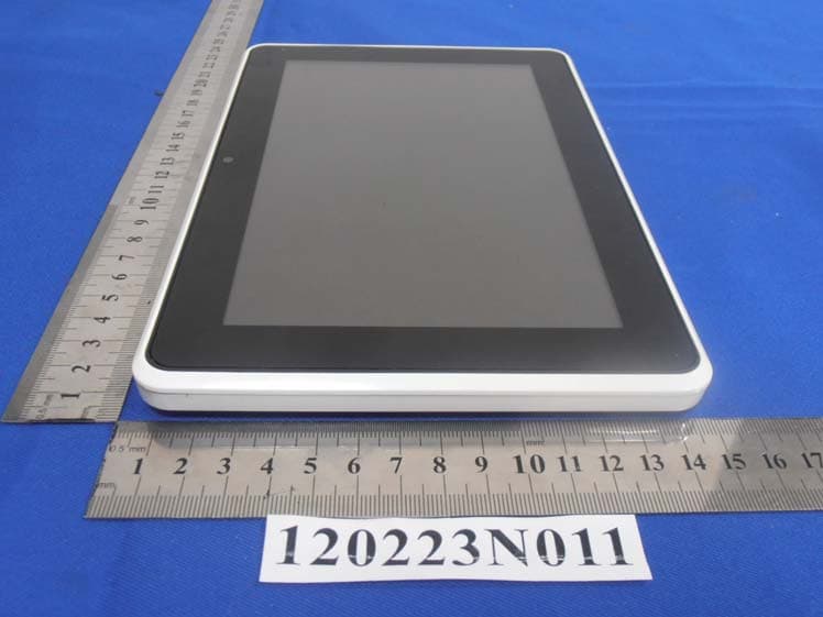
VHH-T860T863E8N8
Mar 27, 2012Tablet
Equipment Class
DTS - Digital Transmission System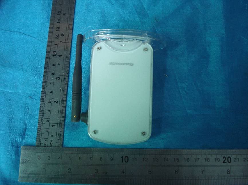
VHH-UTV324
Feb 19, 2008WIRELESS A/V RECEIVER-433 MHZ TX PORTION
Equipment Class
DXX - Part 15 Low Power Communication Device Transmitter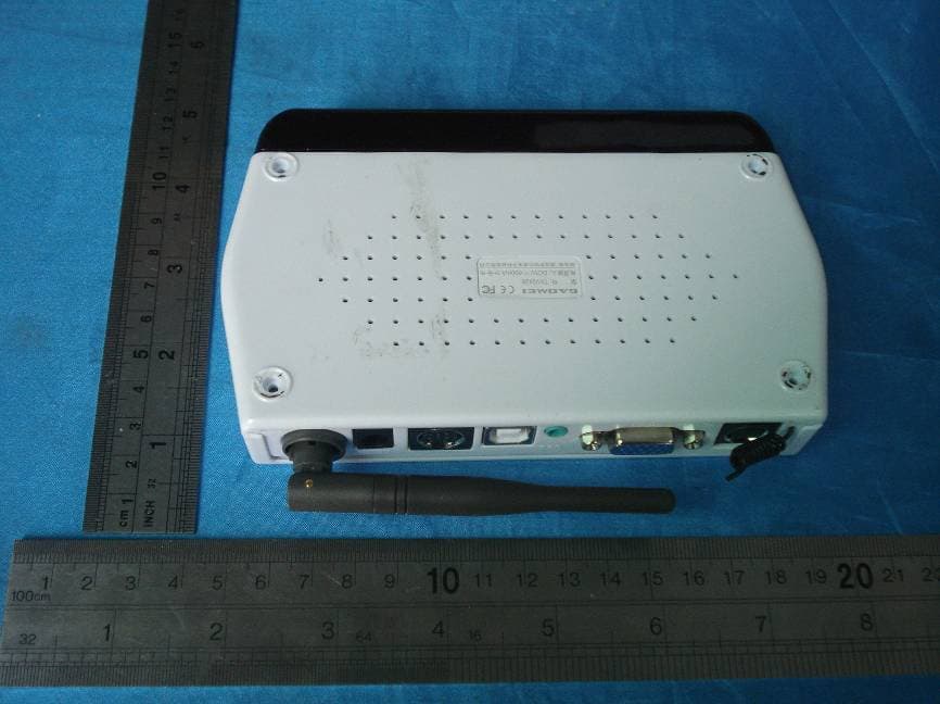
VHH-TXV2428
Jan 13, 2008WIRELESS PC+A/V TRANSMITTER
Equipment Class
DXX - Part 15 Low Power Communication Device Transmitter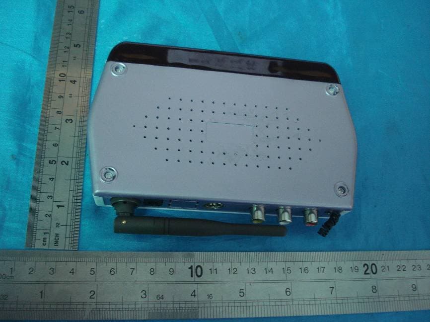
VHH-TXV2408
Jan 13, 2008WIRELESS A/V TRANSMITTER
Equipment Class
DXX - Part 15 Low Power Communication Device Transmitter